2001 NISSAN X-TRAIL differential
[x] Cancel search: differentialPage 2678 of 3833
RFD-2
PRECAUTIONS
PRECAUTIONS
PFP:00001
CautionEDS00101
●Before starting diagnosis of the vehicle, understand symptoms well. Perform correct and systematic oper-
ations.
●Check for the correct installation status prior to removal or disassembly. When mating marks are required,
be sure they do not interfere with the function of the parts they are applied to.
●Carry out an overhaul in a clean work place. Using a dust proof room is recommended.
●Before disassembly, using steam or white gasoline, completely remove sand and mud from the exterior of
the unit, preventing them from entering into the unit during disassembly or assembly.
●Check appearance of the disassembled parts for damage, deformation, and abnormal wear. If a malfunc-
tion is detected, replace it with a new one.
●Normally replace lock pins, oil seals, and bearings with new ones every time they are removed.
●In principle, tighten bolts or nuts gradually in several steps working diagonally from inside to outside. If
tightening sequence is specified, observe it.
●Clean and flush the parts sufficiently and blow them dry.
●Be careful not to damage the sliding surfaces and mating surfaces.
●When applying sealant, remove the old sealant from the mounting surface; then remove any moisture, oil,
and foreign materials from the application and mounting surfaces.
●Always use shop paper for cleaning the inside of components.
●Avoid using cotton gloves or a shop cloth to prevent entering of lint.
●During assembly, observe the specified tightening torque, and apply new differential oil, Vaseline, or Nis-
san MP Special Grease No. 2, as specified for each vehicle, when necessary.
●Do not reuse drained oil. Discard waste oil after oil changes or part treatment in accordance with local
laws and regulations.
Precautions for Brake SystemEDS00102
●When installing rubber parts, final tightening must be carried out under unladen condition* with tires on
ground.
*: Fuel, radiator coolant and engine oil full. Spare tire, jack, hand tools and mats in designated positions.
●After installing removed suspension parts, check wheel alignment and adjust if necessary.
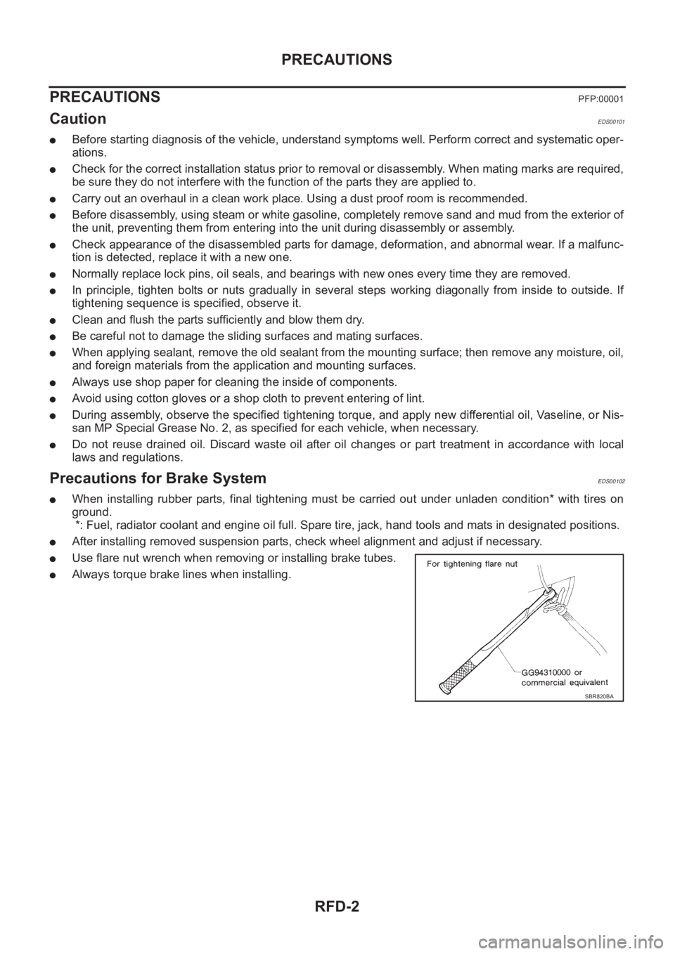
●Use flare nut wrench when removing or installing brake tubes.
●Always torque brake lines when installing.
SBR820BA
Page 2684 of 3833
RFD-8
FRONT OIL SEAL
FRONT OIL SEAL
PFP:38189
Removal and InstallationEDS00106
REMOVAL
1. Remove propeller shaft. Refer to PR-3, "REMOVAL" .
2. Paint mating marks on the final drive companion flange and the thread edge of the electronically con-
trolled coupling.
CAUTION:
Use paint to avoid scratching the surface.
3. Using a differential flange tool, remove companion flange nut to remove companion flange.
4. Using a screwdriver or similar tool, remove oil seal.
INSTALLATION
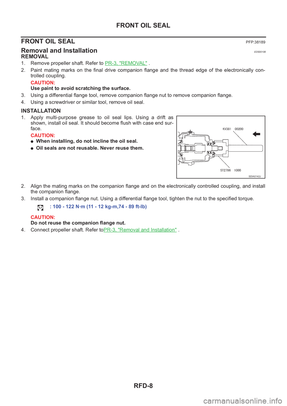
1. Apply multi-purpose grease to oil seal lips. Using a drift as
shown, install oil seal. It should become flush with case end sur-
face.
CAUTION:
●When installing, do not incline the oil seal.
●Oil seals are not reusable. Never reuse them.
2. Align the mating marks on the companion flange and on the electronically controlled coupling, and install
the companion flange.
3. Install a companion flange nut. Using a differential flange tool, tighten the nut to the specified torque.
CAUTION:
Do not reuse the companion flange nut.
4. Connect propeller shaft. Refer toPR-3, "
Removal and Installation" .
SDIA0142J
: 100 - 122 N·m (11 - 12 kg-m,74 - 89 ft-lb)
Page 2692 of 3833
RFD-16
REAR FINAL DRIVE ASSEMBLY
b. Temporarily tighten a dummy cover to the carrier case.
c. Position a dummy cover spacer to the dummy cover.
d. Tighten rear cover mounting bolts to the specified torque.
e. Tighten dummy cover spacer mounting bolts evenly to the spec-
ified torque.
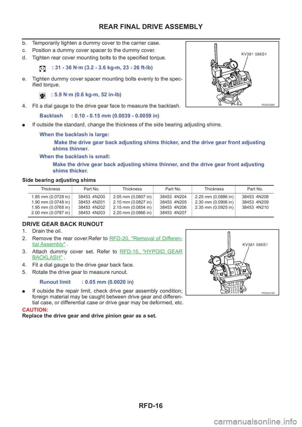
4. Fit a dial gauge to the drive gear face to measure the backlash.
●If outside the standard, change the thickness of the side bearing adjusting shims.
Side bearing adjusting shims
DRIVE GEAR BACK RUNOUT
1. Drain the oil.
2. Remove the rear cover.Refer to RFD-20, "
Removal of Differen-
tial Assembly" .
3. Attach dummy cover set. Refer to RFD-15, "
HYPOID GEAR
BACKLASH" .
4. Fit a dial gauge to the drive gear back face.
5. Rotate the drive gear to measure runout.
●If outside the repair limit, check drive gear assembly condition;
foreign material may be caught between drive gear and differen-
tial case, or differential case or drive gear may be deformed, etc.
CAUTION:
Replace the drive gear and drive pinion gear as a set.: 31 - 36 N·m (3.2 - 3.6 kg-m, 23 - 26 ft-lb)
: 5.9 N·m (0.6 kg-m, 52 in-lb)
Backlash : 0.10 - 0.15 mm (0.0039 - 0.0059 in)
When the backlash is large:
Make the drive gear back adjusting shims thicker, and the drive gear front adjusting
shims thinner.
When the backlash is small:
Make the drive gear back adjusting shims thinner, and the drive gear front adjusting
shims thicker.
PDG0209D
Thickness Part No. Thickness Part No. Thickness Part No.
1.85 mm (0.0728 in)
1.90 mm (0.0748 in)
1.95 mm (0.0768 in)
2.00 mm (0.0787 in)38453 4N200
38453 4N201
38453 4N202
38453 4N2032.05 mm (0.0807 in)
2.10 mm (0.0827 in)
2.15 mm (0.0854 in)
2.20 mm (0.0866 in)38453 4N204
38453 4N205
38453 4N206
38453 4N2072.25 mm (0.0886 in)
2.30 mm (0.0906 in)
2.35 mm (0.0925 in)38453 4N208
38453 4N209
38453 4N210
Runout limit : 0.05 mm (0.0020 in)
PDG0210D
Page 2696 of 3833
RFD-20
REAR FINAL DRIVE ASSEMBLY
Disassembly and Assembly
EDS0010E
DISASSEMBLY
Removal of Electronically Controlled Coupling Assembly
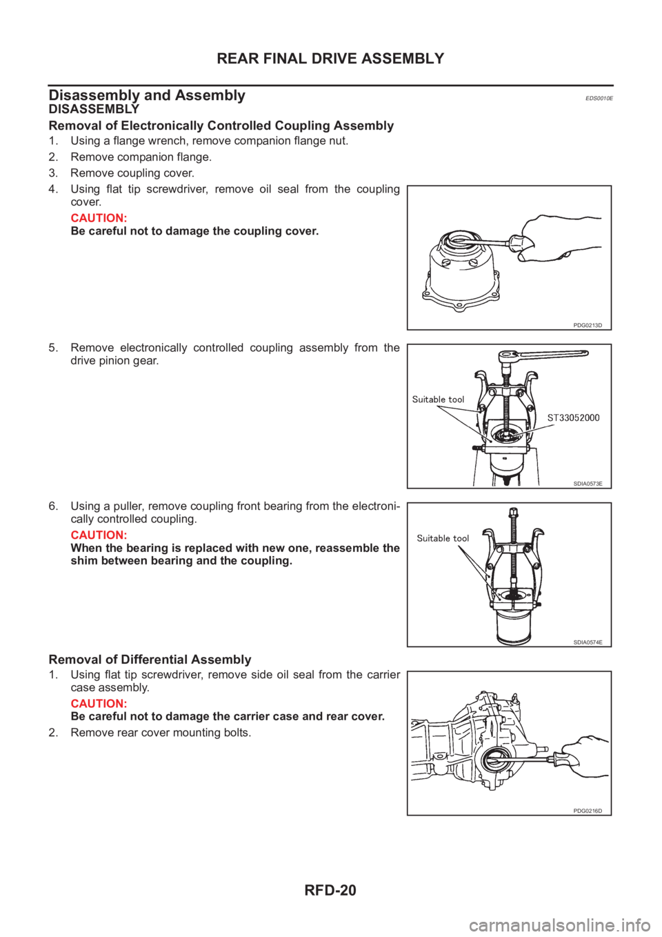
1. Using a flange wrench, remove companion flange nut.
2. Remove companion flange.
3. Remove coupling cover.
4. Using flat tip screwdriver, remove oil seal from the coupling
cover.
CAUTION:
Be careful not to damage the coupling cover.
5. Remove electronically controlled coupling assembly from the
drive pinion gear.
6. Using a puller, remove coupling front bearing from the electroni-
cally controlled coupling.
CAUTION:
When the bearing is replaced with new one, reassemble the
shim between bearing and the coupling.
Removal of Differential Assembly
1. Using flat tip screwdriver, remove side oil seal from the carrier
case assembly.
CAUTION:
Be careful not to damage the carrier case and rear cover.
2. Remove rear cover mounting bolts.
PDG0213D
SDIA0573E
SDIA0574E
PDG0216D
Page 2697 of 3833
REAR FINAL DRIVE ASSEMBLY
RFD-21
C
E
F
G
H
I
J
K
L
MA
B
RFD
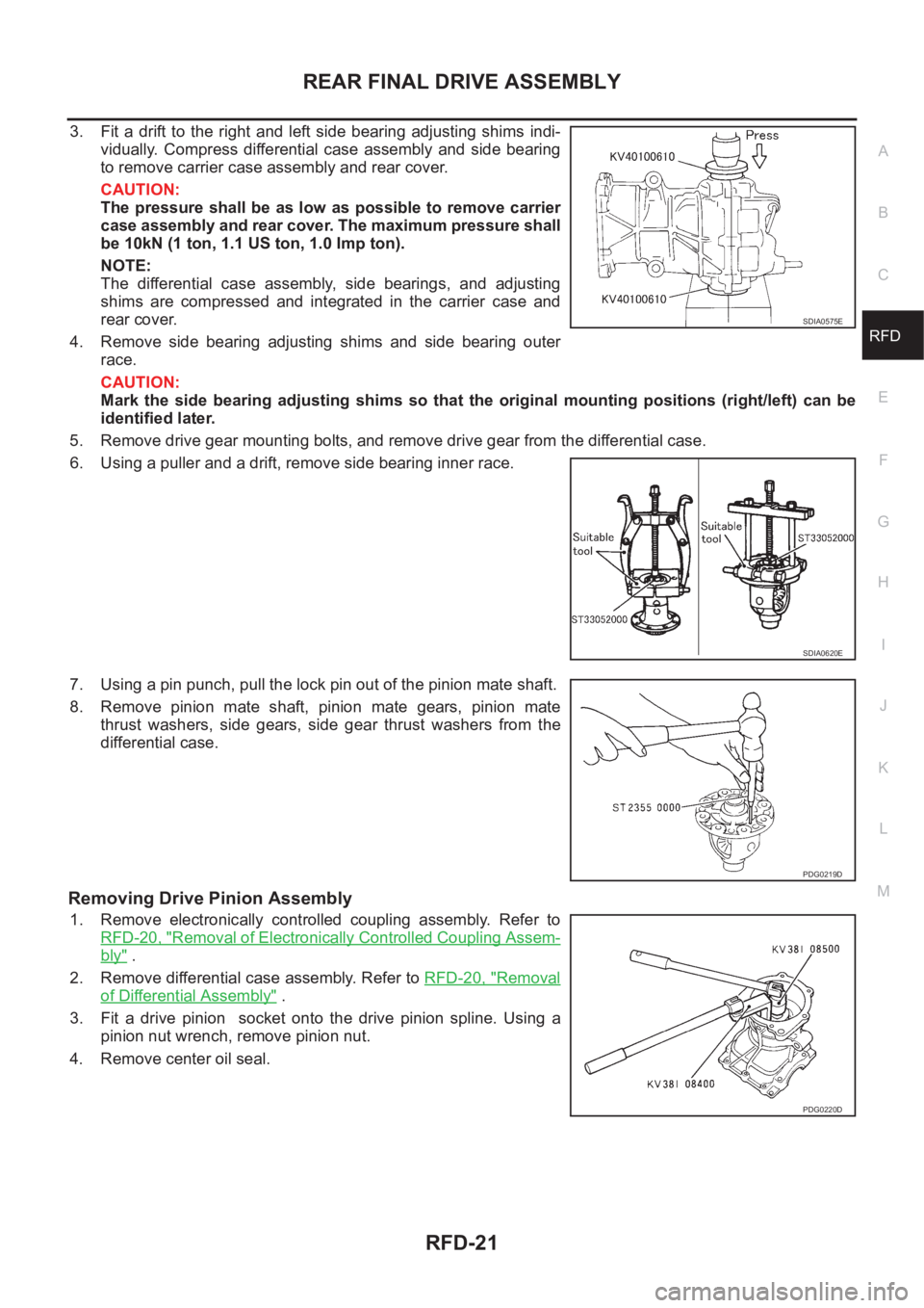
3. Fit a drift to the right and left side bearing adjusting shims indi-
vidually. Compress differential case assembly and side bearing
to remove carrier case assembly and rear cover.
CAUTION:
The pressure shall be as low as possible to remove carrier
case assembly and rear cover. The maximum pressure shall
be 10kN (1 ton, 1.1 US ton, 1.0 Imp ton).
NOTE:
The differential case assembly, side bearings, and adjusting
shims are compressed and integrated in the carrier case and
rear cover.
4. Remove side bearing adjusting shims and side bearing outer
race.
CAUTION:
Mark the side bearing adjusting shims so that the original mounting positions (right/left) can be
identified later.
5. Remove drive gear mounting bolts, and remove drive gear from the differential case.
6. Using a puller and a drift, remove side bearing inner race.
7. Using a pin punch, pull the lock pin out of the pinion mate shaft.
8. Remove pinion mate shaft, pinion mate gears, pinion mate
thrust washers, side gears, side gear thrust washers from the
differential case.
Removing Drive Pinion Assembly
1. Remove electronically controlled coupling assembly. Refer to
RFD-20, "
Removal of Electronically Controlled Coupling Assem-
bly" .
2. Remove differential case assembly. Refer to RFD-20, "
Removal
of Differential Assembly" .
3. Fit a drive pinion socket onto the drive pinion spline. Using a
pinion nut wrench, remove pinion nut.
4. Remove center oil seal.
SDIA0575E
SDIA0620E
PDG0219D
PDG0220D
Page 2699 of 3833
REAR FINAL DRIVE ASSEMBLY
RFD-23
C
E
F
G
H
I
J
K
L
MA
B
RFD
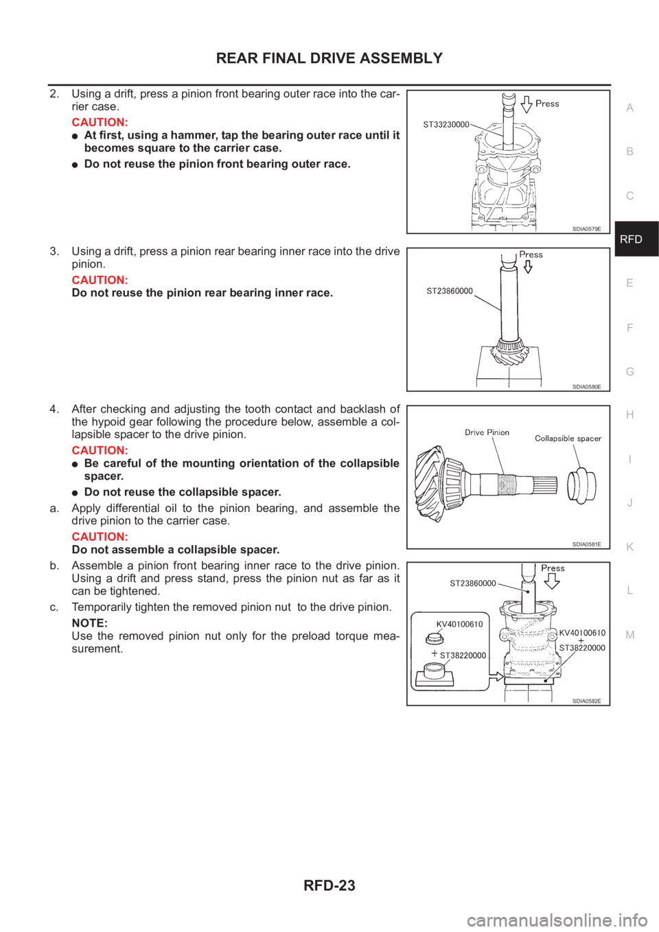
2. Using a drift, press a pinion front bearing outer race into the car-
rier case.
CAUTION:
●At first, using a hammer, tap the bearing outer race until it
becomes square to the carrier case.
●Do not reuse the pinion front bearing outer race.
3. Using a drift, press a pinion rear bearing inner race into the drive
pinion.
CAUTION:
Do not reuse the pinion rear bearing inner race.
4. After checking and adjusting the tooth contact and backlash of
the hypoid gear following the procedure below, assemble a col-
lapsible spacer to the drive pinion.
CAUTION:
●Be careful of the mounting orientation of the collapsible
spacer.
●Do not reuse the collapsible spacer.
a. Apply differential oil to the pinion bearing, and assemble the
drive pinion to the carrier case.
CAUTION:
Do not assemble a collapsible spacer.
b. Assemble a pinion front bearing inner race to the drive pinion.
Using a drift and press stand, press the pinion nut as far as it
can be tightened.
c. Temporarily tighten the removed pinion nut to the drive pinion.
NOTE:
Use the removed pinion nut only for the preload torque mea-
surement.
SDIA0579E
SDIA0580E
SDIA0581E
SDIA0582E
Page 2700 of 3833
RFD-24
REAR FINAL DRIVE ASSEMBLY
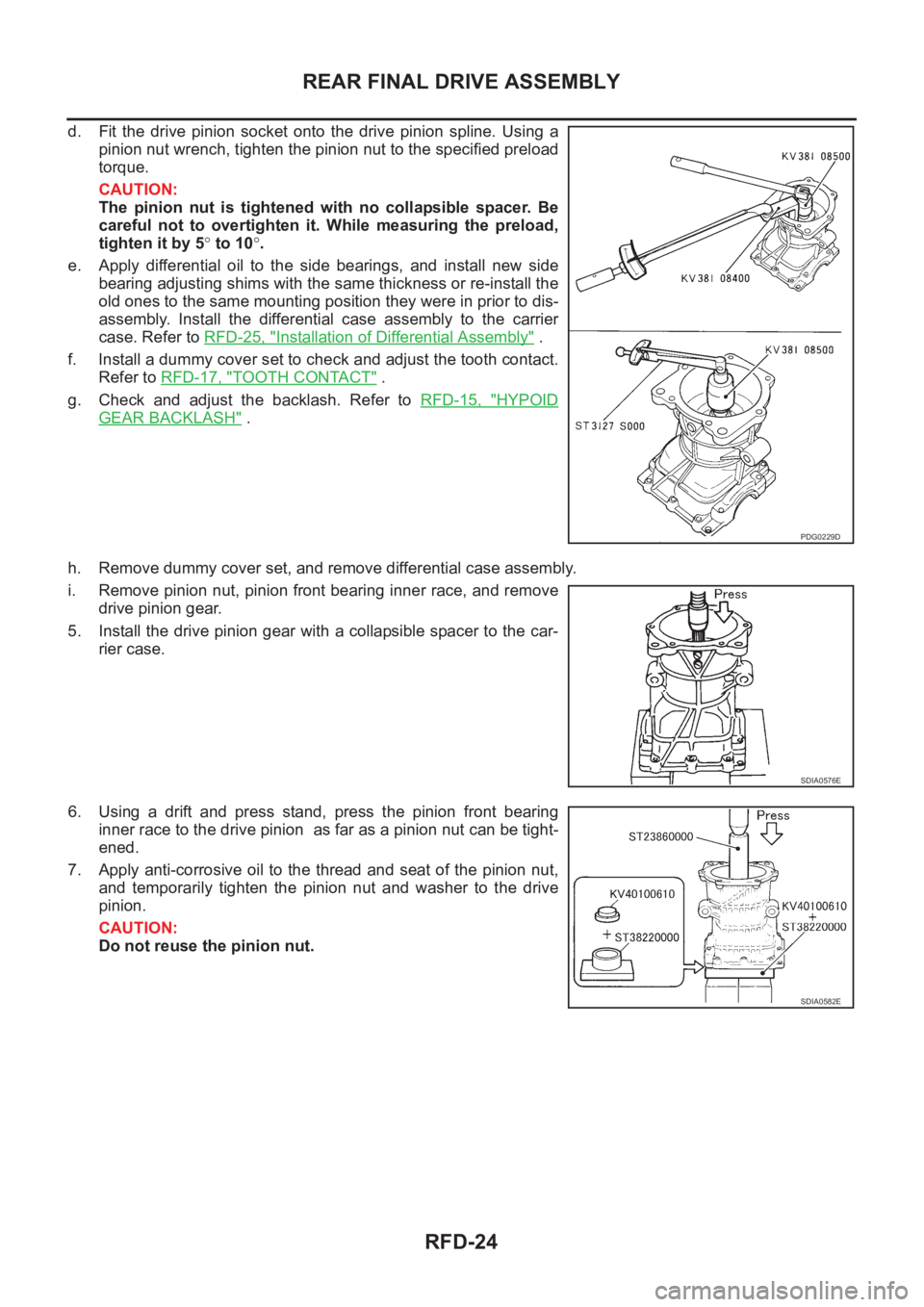
d. Fit the drive pinion socket onto the drive pinion spline. Using a
pinion nut wrench, tighten the pinion nut to the specified preload
torque.
CAUTION:
The pinion nut is tightened with no collapsible spacer. Be
careful not to overtighten it. While measuring the preload,
tighten it by 5° to 10°.
e. Apply differential oil to the side bearings, and install new side
bearing adjusting shims with the same thickness or re-install the
old ones to the same mounting position they were in prior to dis-
assembly. Install the differential case assembly to the carrier
case. Refer to RFD-25, "
Installation of Differential Assembly" .
f. Install a dummy cover set to check and adjust the tooth contact.
Refer to RFD-17, "
TOOTH CONTACT" .
g. Check and adjust the backlash. Refer to RFD-15, "
HYPOID
GEAR BACKLASH" .
h. Remove dummy cover set, and remove differential case assembly.
i. Remove pinion nut, pinion front bearing inner race, and remove
drive pinion gear.
5. Install the drive pinion gear with a collapsible spacer to the car-
rier case.
6. Using a drift and press stand, press the pinion front bearing
inner race to the drive pinion as far as a pinion nut can be tight-
ened.
7. Apply anti-corrosive oil to the thread and seat of the pinion nut,
and temporarily tighten the pinion nut and washer to the drive
pinion.
CAUTION:
Do not reuse the pinion nut.
PDG0229D
SDIA0576E
SDIA0582E
Page 2701 of 3833
REAR FINAL DRIVE ASSEMBLY
RFD-25
C
E
F
G
H
I
J
K
L
MA
B
RFD
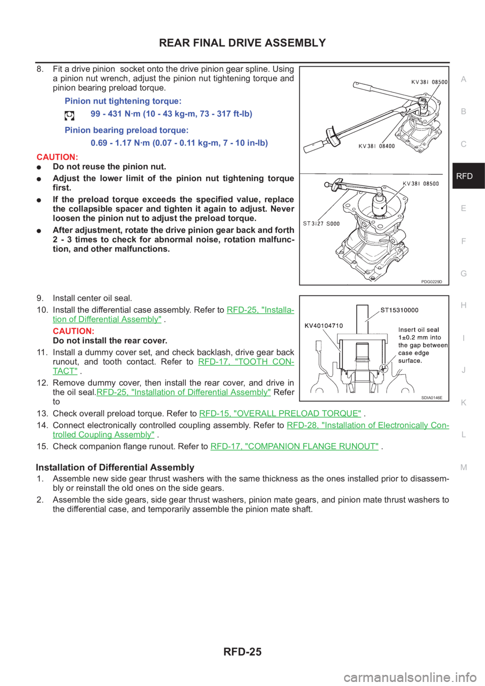
8. Fit a drive pinion socket onto the drive pinion gear spline. Using
a pinion nut wrench, adjust the pinion nut tightening torque and
pinion bearing preload torque.
CAUTION:
●Do not reuse the pinion nut.
●Adjust the lower limit of the pinion nut tightening torque
first.
●If the preload torque exceeds the specified value, replace
the collapsible spacer and tighten it again to adjust. Never
loosen the pinion nut to adjust the preload torque.
●After adjustment, rotate the drive pinion gear back and forth
2 - 3 times to check for abnormal noise, rotation malfunc-
tion, and other malfunctions.
9. Install center oil seal.
10. Install the differential case assembly. Refer to RFD-25, "
Installa-
tion of Differential Assembly" .
CAUTION:
Do not install the rear cover.
11. Install a dummy cover set, and check backlash, drive gear back
runout, and tooth contact. Refer to RFD-17, "
TOOTH CON-
TA C T" .
12. Remove dummy cover, then install the rear cover, and drive in
the oil seal.RFD-25, "
Installation of Differential Assembly" Refer
to
13. Check overall preload torque. Refer to RFD-15, "
OVERALL PRELOAD TORQUE" .
14. Connect electronically controlled coupling assembly. Refer to RFD-28, "
Installation of Electronically Con-
trolled Coupling Assembly" .
15. Check companion flange runout. Refer to RFD-17, "
COMPANION FLANGE RUNOUT" .
Installation of Differential Assembly
1. Assemble new side gear thrust washers with the same thickness as the ones installed prior to disassem-
bly or reinstall the old ones on the side gears.
2. Assemble the side gears, side gear thrust washers, pinion mate gears, and pinion mate thrust washers to
the differential case, and temporarily assemble the pinion mate shaft. Pinion nut tightening torque:
99 - 431 N·m (10 - 43 kg-m, 73 - 317 ft-lb)
Pinion bearing preload torque:
0.69 - 1.17 N·m (0.07 - 0.11 kg-m, 7 - 10 in-lb)
PDG0229D
SDIA0146E