2001 NISSAN X-TRAIL differential
[x] Cancel search: differentialPage 2070 of 3833
MT-94
FINAL DRIVE
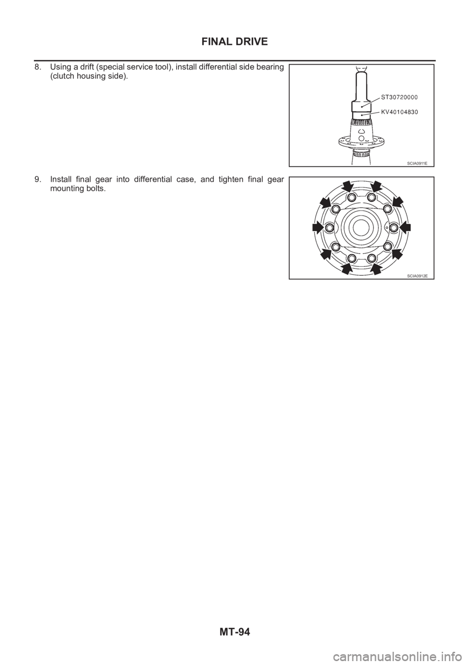
8. Using a drift (special service tool), install differential side bearing
(clutch housing side).
9. Install final gear into differential case, and tighten final gear
mounting bolts.
SCIA0911E
SCIA0912E
Page 2076 of 3833
MT-100
SERVICE DATA AND SPECIFICATIONS (SDS)
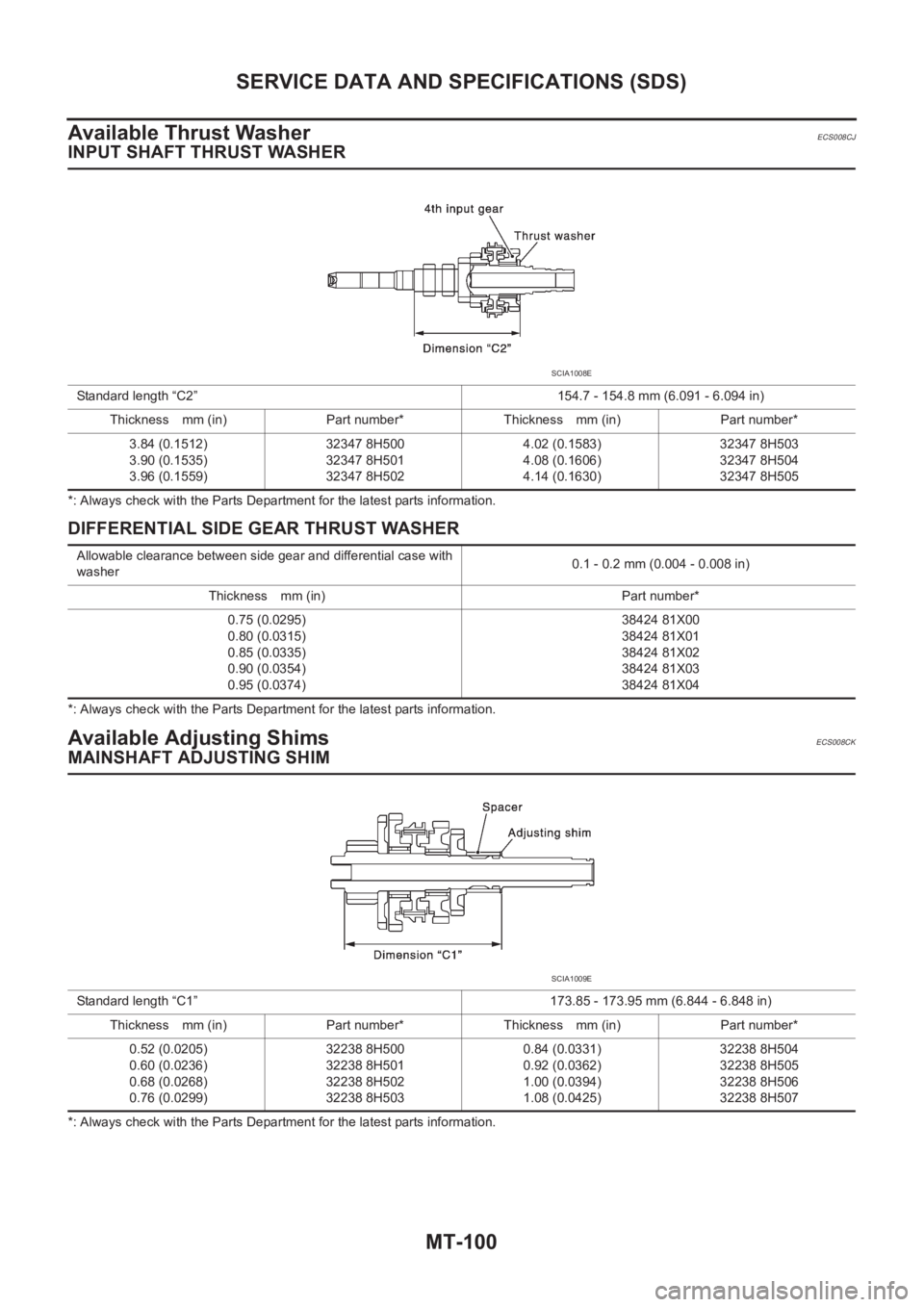
Available Thrust Washer
ECS008CJ
INPUT SHAFT THRUST WASHER
*: Always check with the Parts Department for the latest parts information.
DIFFERENTIAL SIDE GEAR THRUST WASHER
*: Always check with the Parts Department for the latest parts information.
Available Adjusting ShimsECS008CK
MAINSHAFT ADJUSTING SHIM
*: Always check with the Parts Department for the latest parts information. Standard length “C2” 154.7 - 154.8 mm (6.091 - 6.094 in)
Thickness mm (in) Part number* Thickness mm (in) Part number*
3.84 (0.1512)
3.90 (0.1535)
3.96 (0.1559)32347 8H500
32347 8H501
32347 8H5024.02 (0.1583)
4.08 (0.1606)
4.14 (0.1630)32347 8H503
32347 8H504
32347 8H505
SCIA1008E
Allowable clearance between side gear and differential case with
washer0.1 - 0.2 mm (0.004 - 0.008 in)
Thickness mm (in) Part number*
0.75 (0.0295)
0.80 (0.0315)
0.85 (0.0335)
0.90 (0.0354)
0.95 (0.0374)38424 81X00
38424 81X01
38424 81X02
38424 81X03
38424 81X04
Standard length “C1” 173.85 - 173.95 mm (6.844 - 6.848 in)
Thickness mm (in) Part number* Thickness mm (in) Part number*
0.52 (0.0205)
0.60 (0.0236)
0.68 (0.0268)
0.76 (0.0299)32238 8H500
32238 8H501
32238 8H502
32238 8H5030.84 (0.0331)
0.92 (0.0362)
1.00 (0.0394)
1.08 (0.0425)32238 8H504
32238 8H505
32238 8H506
32238 8H507
SCIA1009E
Page 2078 of 3833
MT-102
SERVICE DATA AND SPECIFICATIONS (SDS)
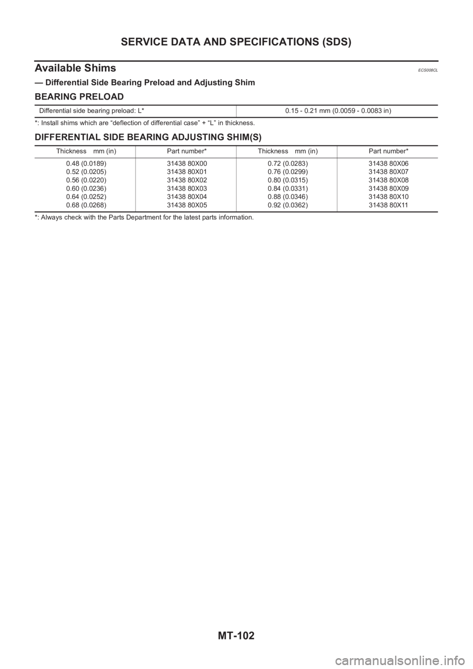
Available Shims
ECS008CL
— Differential Side Bearing Preload and Adjusting Shim
BEARING PRELOAD
*: Install shims which are “deflection of differential case” + “L” in thickness.
DIFFERENTIAL SIDE BEARING ADJUSTING SHIM(S)
*: Always check with the Parts Department for the latest parts information. Differential side bearing preload: L* 0.15 - 0.21 mm (0.0059 - 0.0083 in)
Thickness mm (in) Part number* Thickness mm (in) Part number*
0.48 (0.0189)
0.52 (0.0205)
0.56 (0.0220)
0.60 (0.0236)
0.64 (0.0252)
0.68 (0.0268)31438 80X00
31438 80X01
31438 80X02
31438 80X03
31438 80X04
31438 80X050.72 (0.0283)
0.76 (0.0299)
0.80 (0.0315)
0.84 (0.0331)
0.88 (0.0346)
0.92 (0.0362)31438 80X06
31438 80X07
31438 80X08
31438 80X09
31438 80X10
31438 80X11
Page 2081 of 3833
AT-3
D
E
F
G
H
I
J
K
L
MA
B
AT TION ........................................................................ 287
Symptom Chart .................................................... 287
TCM Terminals and Reference Value ................... 306
CAN COMMUNICATION ........................................ 309
System Description .............................................. 309
TROUBLE DIAGNOSES FOR SYMPTOMS .......... 310
Wiring Diagram — AT — NONDTC ...................... 310
O/D OFF Indicator Lamp Does Not Come On ..... 312
Engine Cannot Be Started In “P” and “N” Position . 314
In “P” Position, Vehicle Moves Forward Or Back-
ward When Pushed .............................................. 315
In “N” Position, Vehicle Moves ............................. 315
Large Shock. “N” → “R” Position .......................... 317
Vehicle Does Not Creep Backward In “R” Position . 318
Vehicle Does Not Creep Forward In “D”, “2” Or “1”
Position ................................................................ 321
Vehicle Cannot Be Started From D
1 ..................... 323
A/T Does Not Shift: D
1→ D2 Or Does Not Kick down:
D
4→ D2 ............................................................... 326
A/T Does Not Shift: D
2→ D3 ............................... 328
A/T Does Not Shift: D
3→ D4 ............................... 330
A/T Does Not Perform Lock-up ............................ 332
A/T Does Not Hold Lock-up Condition ................. 333
Lock-up Is Not Released ...................................... 335
Engine Speed Does Not Return To Idle (Light Brak-
ing D
4→ D3 ) ....................................................... 336
Vehicle Does Not Start From D
1 ........................... 338
A/T Does Not Shift: D
4→ D3 , When Overdrive Con-
trol Switch “ON” → “OFF” ..................................... 339
A/T Does Not Shift: D
3→ 22 , W h e n S e l e c t o r L e v e r
“D”→ “2” Position ................................................ 340
A/T Does Not Shift: 2
2→ 11 , W h e n S e l e c t o r L e v e r
“2” → “1” Position ................................................. 341
Vehicle Does Not Decelerate By Engine Brake ... 343
TCM Self-diagnosis Does Not Activate ................ 344
ALL
MAIN POWER SUPPLY AND GROUND CIRCUIT . 350
Wiring Diagram — AT — MAIN ............................ 350
Diagnostic Procedure ........................................... 351
VEHICLE SPEED SENSOR·A/T (REVOLUTION
SENSOR) ................................................................ 353
Description ........................................................... 353
Wiring Diagram — AT — VSSA/T ........................ 355
Diagnostic Procedure ........................................... 356
DTC VEHICLE SPEED SENSOR MTR .................. 358
Description ........................................................... 358
Wiring Diagram — AT — VSSMTR ...................... 360
Diagnostic Procedure ........................................... 361
ACCELE RATOR PEDAL POSITION (APP) SEN-
SOR ........................................................................ 362
Description ........................................................... 362
Wiring Diagram — AT — TPS .............................. 364
Diagnostic Procedure ........................................... 365
SHIFT SOLENOID VALVE A .................................. 367
Description ........................................................... 367
Wiring Diagram — AT — SSV/A .......................... 369Diagnostic Procedure ...........................................370
Component Inspection ..........................................371
SHIFT SOLENOID VALVE B ..................................372
Description ............................................................372
Wiring Diagram — AT — SSV/B ...........................374
Diagnostic Procedure ...........................................375
Component Inspection ..........................................376
OVERRUN CLUTCH SOLENOID VALVE ...............377
Description ............................................................377
Wiring Diagram — AT — OVRCSV ......................378
Diagnostic Procedure ...........................................379
Component Inspection ..........................................380
TORQUE CONVERTER CLUTCH SOLENOID
VALVE .....................................................................381
Description ............................................................381
Wiring Diagram — AT — TCV ..............................383
Diagnostic Procedure ...........................................384
Component Inspection ..........................................385
BATT/FLUID TEMP SEN (A/T FLUID TEMP SEN-
SOR CIRCUIT AND TCM POWER SOURCE) .......386
Description ............................................................386
Wiring Diagram — AT — BA/FTS .........................388
Diagnostic Procedure ...........................................389
Component Inspection ..........................................391
ENGINE SPEED SIGNAL .......................................392
Description ............................................................392
Wiring Diagram — AT — ENGSS .........................393
Diagnostic Procedure ...........................................394
LINE PRESSURE SOLENOID VALVE ..................
.396
Description ............................................................396
Wiring Diagram — AT — LPSV ............................398
Diagnostic Procedure ...........................................399
Component Inspection ..........................................401
CAN COMMUNICATION LINE ...............................403
Description ............................................................403
On Board Diagnosis Logic ....................................403
Self-Diagnosis Code Confirmation Procedure ......403
Wiring Diagram — AT — CAN ..............................404
Diagnostic Procedure ...........................................405
A/T SHIFT LOCK SYSTEM ....................................406
Description ............................................................406
Shift Lock System Electrical Parts Location .........406
Wiring Diagram — SHIFT — ................................407
Diagnostic Procedure ...........................................408
KEY INTERLOCK CABLE ......................................412
Components .........................................................412
Removal ...............................................................412
Installation ............................................................413
ON-VEHICLE SERVICE ..........................................414
Control Valve Assembly and Accumulators ..........414
Control Cable Adjustment .....................................416
Park/Neutral Position (PNP) Switch Adjustment ..416
Differential Side Oil Seal Replacement ................417
Revolution Sensor Replacement ..........................417
REMOVAL AND INSTALLATION ...........................418
Removal ...............................................................418
Installation ............................................................419
OVERHAUL ............................................................421
Components .........................................................421
Page 2087 of 3833
PREPARATION
AT-9
D
E
F
G
H
I
J
K
L
MA
B
AT
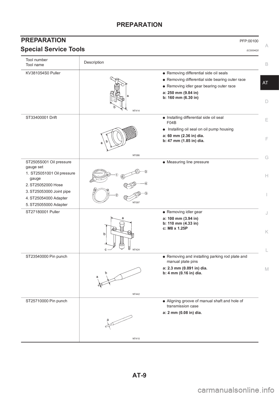
PREPARATIONPFP:00100
Special Service ToolsECS004Q5
Tool number
Tool nameDescription
KV381054S0 Puller
●Removing differential side oil seals
●Removing differential side bearing outer race
●Removing idler gear bearing outer race
a: 250 mm (9.84 in)
b: 160 mm (6.30 in)
ST33400001 Drift
●Installing differential side oil seal
F04B
● Installing oil seal on oil pump housing
a: 60 mm (2.36 in) dia.
b: 47 mm (1.85 in) dia.
ST2505S001 Oil pressure
gauge set
1. ST25051001 Oil pressure
gauge
2. ST25052000 Hose
3. ST25053000 Joint pipe
4. ST25054000 Adapter
5. ST25055000 Adapter
●Measuring line pressure
ST27180001 Puller
●Removing idler gear
a: 100 mm (3.94 in)
b: 110 mm (4.33 in)
c: M8 x 1.25P
ST23540000 Pin punch
●Removing and installing parking rod plate and
manual plate pins
a: 2.3 mm (0.091 in) dia.
b: 4 mm (0.16 in) dia.
ST25710000 Pin punch
●Aligning groove of manual shaft and hole of
transmission case
a: 2 mm (0.08 in) dia.
NT414
NT086
NT097
NT424
NT442
NT410
Page 2088 of 3833
AT-10
PREPARATION
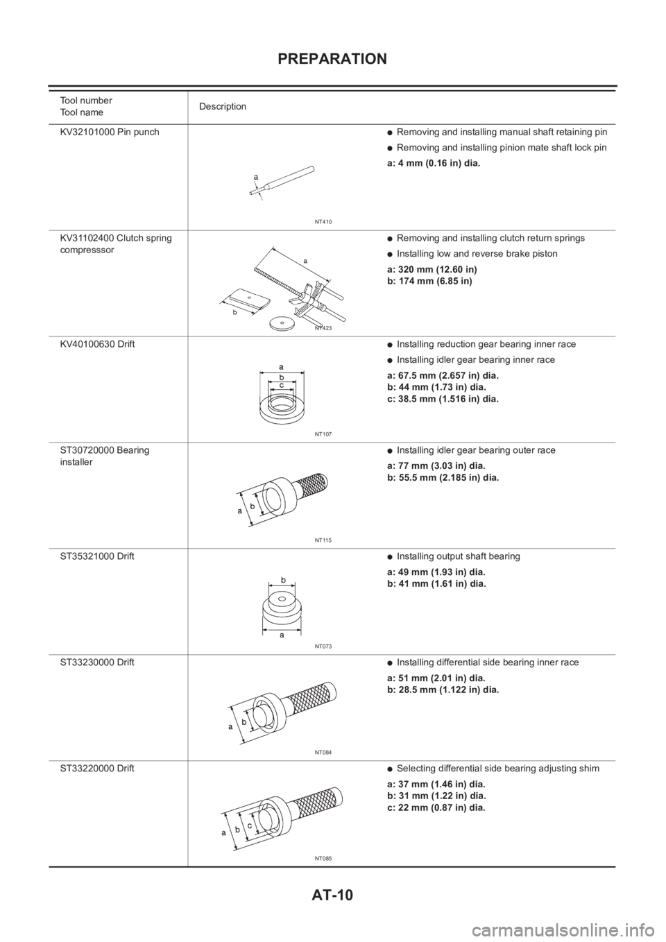
KV32101000 Pin punch ●Removing and installing manual shaft retaining pin
●Removing and installing pinion mate shaft lock pin
a: 4 mm (0.16 in) dia.
KV31102400 Clutch spring
compresssor
●Removing and installing clutch return springs
●Installing low and reverse brake piston
a: 320 mm (12.60 in)
b: 174 mm (6.85 in)
KV40100630 Drift
●Installing reduction gear bearing inner race
●Installing idler gear bearing inner race
a: 67.5 mm (2.657 in) dia.
b: 44 mm (1.73 in) dia.
c: 38.5 mm (1.516 in) dia.
ST30720000 Bearing
installer
●Installing idler gear bearing outer race
a: 77 mm (3.03 in) dia.
b: 55.5 mm (2.185 in) dia.
ST35321000 Drift
●Installing output shaft bearing
a: 49 mm (1.93 in) dia.
b: 41 mm (1.61 in) dia.
ST33230000 Drift
●Installing differential side bearing inner race
a: 51 mm (2.01 in) dia.
b: 28.5 mm (1.122 in) dia.
ST33220000 Drift
●Selecting differential side bearing adjusting shim
a: 37 mm (1.46 in) dia.
b: 31 mm (1.22 in) dia.
c: 22 mm (0.87 in) dia. Tool number
Tool nameDescription
NT410
NT423
NT107
NT115
NT073
NT084
NT085
Page 2089 of 3833
PREPARATION
AT-11
D
E
F
G
H
I
J
K
L
MA
B
AT
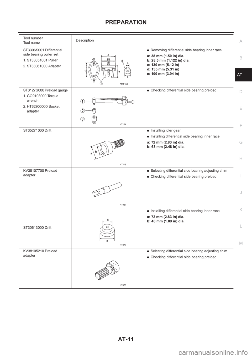
ST3306S001 Differential
side bearing puller set
1. ST33051001 Puller
2. ST33061000 Adapter●Removing differential side bearing inner race
a: 38 mm (1.50 in) dia.
b: 28.5 mm (1.122 in) dia.
c: 130 mm (5.12 in)
d: 135 mm (5.31 in)
e: 100 mm (3.94 in)
ST3127S000 Preload gauge
1. GG9103000 Torque
wrench
2. HT62900000 Socket
adapter
●Checking differential side bearing preload
ST35271000 Drift
●Installing idler gear
●Installing differential side bearing inner race
a: 72 mm (2.83 in) dia.
b: 63 mm (2.48 in) dia.
KV38107700 Preload
adapter
●Selecting differential side bearing adjusting shim
●Checking differential side bearing preload
ST30613000 Drift
●Installing differential side bearing inner race
a: 72 mm (2.83 in) dia.
b: 48 mm (1.89 in) dia.
KV38105210 Preload
adapter
●Selecting differential side bearing adjusting shim
●Checking differential side bearing preload Tool number
Tool nameDescription
AMT153
NT124
NT115
NT087
NT073
NT075
Page 2090 of 3833
AT-12
PREPARATION
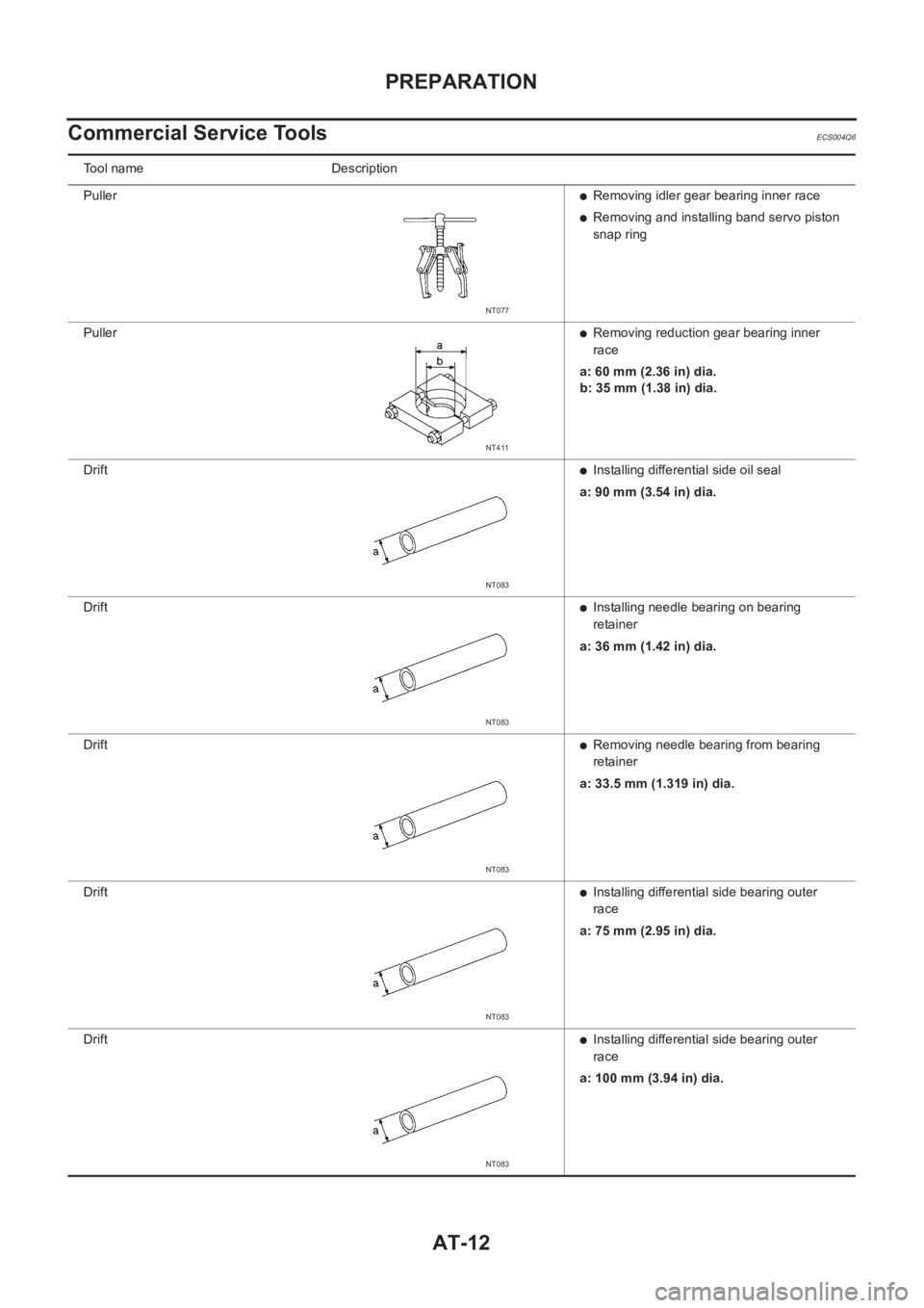
Commercial Service Tools
ECS004Q6
Tool name Description
Puller
●Removing idler gear bearing inner race
●Removing and installing band servo piston
snap ring
Puller
●Removing reduction gear bearing inner
race
a: 60 mm (2.36 in) dia.
b: 35 mm (1.38 in) dia.
Drift
●Installing differential side oil seal
a: 90 mm (3.54 in) dia.
Drift
●Installing needle bearing on bearing
retainer
a: 36 mm (1.42 in) dia.
Drift
●Removing needle bearing from bearing
retainer
a: 33.5 mm (1.319 in) dia.
Drift
●Installing differential side bearing outer
race
a: 75 mm (2.95 in) dia.
Drift
●Installing differential side bearing outer
race
a: 100 mm (3.94 in) dia.
NT077
NT411
NT083
NT083
NT083
NT083
NT083