2001 NISSAN X-TRAIL App sensor
[x] Cancel search: App sensorPage 2901 of 3833
![NISSAN X-TRAIL 2001 Service Repair Manual TROUBLE DIAGNOSIS
BRC-117
[ESP/TCS/ABS]
C
D
E
G
H
I
J
K
L
MA
B
BRC
3.SYMPTOM CHECK 3
Does the symptom appear during normal braking operation?
CAUTION:
ABS may work in following driving conditions even NISSAN X-TRAIL 2001 Service Repair Manual TROUBLE DIAGNOSIS
BRC-117
[ESP/TCS/ABS]
C
D
E
G
H
I
J
K
L
MA
B
BRC
3.SYMPTOM CHECK 3
Does the symptom appear during normal braking operation?
CAUTION:
ABS may work in following driving conditions even](/manual-img/5/57405/w960_57405-2900.png)
TROUBLE DIAGNOSIS
BRC-117
[ESP/TCS/ABS]
C
D
E
G
H
I
J
K
L
MA
B
BRC
3.SYMPTOM CHECK 3
Does the symptom appear during normal braking operation?
CAUTION:
ABS may work in following driving conditions even if there is no sudden brake.
●When road friction is low.
●High speed cornering
●When a gust of wind
Is inspection result OK?
YES >> GO TO 4.
NO >> Normal
4.SYMPTOM CHECK 4
Check that the symptom is reproduce when the engine speed is increased with the vehicle stopped.
Is inspection result OK?
YES >> GO TO 5.
NO >>
●Normal.
CAUTION:
This symptom may appear with vehicle stopped.
5.SYMPTOM CHECK 5
Check that the symptom is reproduce when any switch of electrical equipment is operated.
Is inspection result OK?
YES >> Check that there are no radio, antenna, and antenna lead-in wires (including wiring) near control
unit.
NO >> GO TO 6.
6.ABS WARNING LAMP INSPECTION
Check that the ABS warning lamp turns on.
Is inspection result OK?
YES >> Perform the self-diagnosis.
NO >> GO TO 7.
7.WHEEL SENSOR INSPECTION
Check the wheel sensor system.
●Sensor mounting inspection
●Sensor pick-up inspection for iron chips (e.g. Number of teeth, damaged teeth)
●Sensor connector engagement inspection
●Wheel sensor path harness and connector inspection
Is inspection result OK?
YES >> Normal
NO >> Wheel sensor and rotor lines repair
Symptom 6: ESP OFF Indicator Lamp Does Not IlluminateEFS001AX
Inspection procedure
1.ESP OFF INDICATOR LAMP INSPECTION
Disconnect the ESP/TCS/ABS control unit connector.
Does the ABS warning lamp and ESP OFF indicator lamp illuminate?
YES >> ESP/TCS/ABS control unit malfunction. Repair or replace the control unit.
NO >> Combination meter system malfunction. Check the combination meter.
Page 2903 of 3833
![NISSAN X-TRAIL 2001 Service Repair Manual TROUBLE DIAGNOSIS
BRC-119
[ESP/TCS/ABS]
C
D
E
G
H
I
J
K
L
MA
B
BRC
3.ECM SELF-DIAGNOSIS RESULT CHECK
Perform the ECM self-diagnosis.
Is the self-diagnosis results indicated?
YES >> Repair or replace t NISSAN X-TRAIL 2001 Service Repair Manual TROUBLE DIAGNOSIS
BRC-119
[ESP/TCS/ABS]
C
D
E
G
H
I
J
K
L
MA
B
BRC
3.ECM SELF-DIAGNOSIS RESULT CHECK
Perform the ECM self-diagnosis.
Is the self-diagnosis results indicated?
YES >> Repair or replace t](/manual-img/5/57405/w960_57405-2902.png)
TROUBLE DIAGNOSIS
BRC-119
[ESP/TCS/ABS]
C
D
E
G
H
I
J
K
L
MA
B
BRC
3.ECM SELF-DIAGNOSIS RESULT CHECK
Perform the ECM self-diagnosis.
Is the self-diagnosis results indicated?
YES >> Repair or replace the camshaft position sensor system.
NO >> GO TO 4.
4.SELF-DIAGNOSIS RESULT 2
Disconnect connectors for the ESP/TCS/ABS control unit and ECM, and reconnect them correctly to perform
the self-diagnosis again.
Is inspection result OK?
YES >> GO TO 5.
NO >> Connector malfunction. Repair or replace the connector.
5.SELF-DIAGNOSIS RESULT CHECK 3
Perform the 4WD control unit self-diagnosis.
Is inspection result OK?
YES >> GO TO 6.
NO >> Repair or replace the applicable part.
6.SELF-DIAGNOSIS RESULT CHECK 4
Perform the ESP/TCS/ABS control unit self-diagnosis again.
Is the self-diagnosis results displayed?
YES >> Repair or replace the applicable item.
NO >> GO TO 7.
7.CIRCUIT CHECK BETWEEN ESP/TCS/ABS CONTROL UNIT AND ECM
1. Disconnect connectors for the ESP/TCS/ABS control unit and ECM.
2. Check the engine speed signal harness between the ESP/TCS/ABScontrol unit and ECM for an open/
shorted circuit.
3. Check connectors for the ESP/TCS/ABS control unit and ECM.
Is inspection result OK?
YES >> Inspection End
NO >> Repair or replace the applicable item and perform the ESP/TCS/ABS control unit self-diagnosis
again.
Page 2959 of 3833
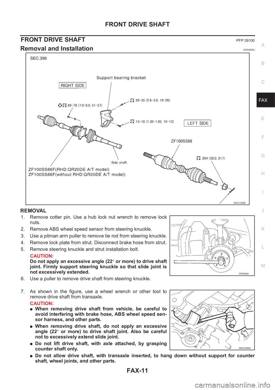
FRONT DRIVE SHAFT
FAX-11
C
E
F
G
H
I
J
K
L
MA
B
FA X
FRONT DRIVE SHAFTPFP:39100
Removal and InstallationEDS0005U
REMOVAL
1. Remove cotter pin. Use a hub lock nut wrench to remove lock
nuts.
2. Remove ABS wheel speed sensor from steering knuckle.
3. Use a pitman arm puller to remove tie rod from steering knuckle.
4. Remove lock plate from strut. Disconnect brake hose from strut.
5. Remove steering knuckle and strut installation bolt.
CAUTION:
Do not apply an excessive angle (22° or more) to drive shaft
joint. Firmly support steering knuckle so that slide joint is
not excessively extended.
6. Use a puller to remove drive shaft from steering knuckle.
7. As shown in the figure, use a wheel wrench or other tool to
remove drive shaft from transaxle.
CAUTION:
●When removing drive shaft from vehicle, be careful to
avoid interfering with brake hose, ABS wheel speed sen-
sor harness, and other parts.
●When removing drive shaft, do not apply an excessive
angle (22° or more) to drive shaft joint. Also be careful
not to excessively extend slide joint.
●Do not lift drive shaft, with axle attached, by grasping
counter shaft only.
●Do not allow drive shaft, with transaxle inserted, to hang down without support for counter
shaft, wheel joints, and other parts.
SDIA1390E
SFA649A
MAA0384D
Page 2960 of 3833
FAX-12
FRONT DRIVE SHAFT
●When the drive shafts listed below have been removed, check that a circular clip is attached to the end.
×: Applicable
–: Not applicable
●Remove installation bolt from right-side drive shaft support bearing bracket. Then remove bracket from
engine.
●Remove installation bolt from right-side drive shaft and remove drive shaft from side shaft.
INSPECTION AFTER REMOVAL
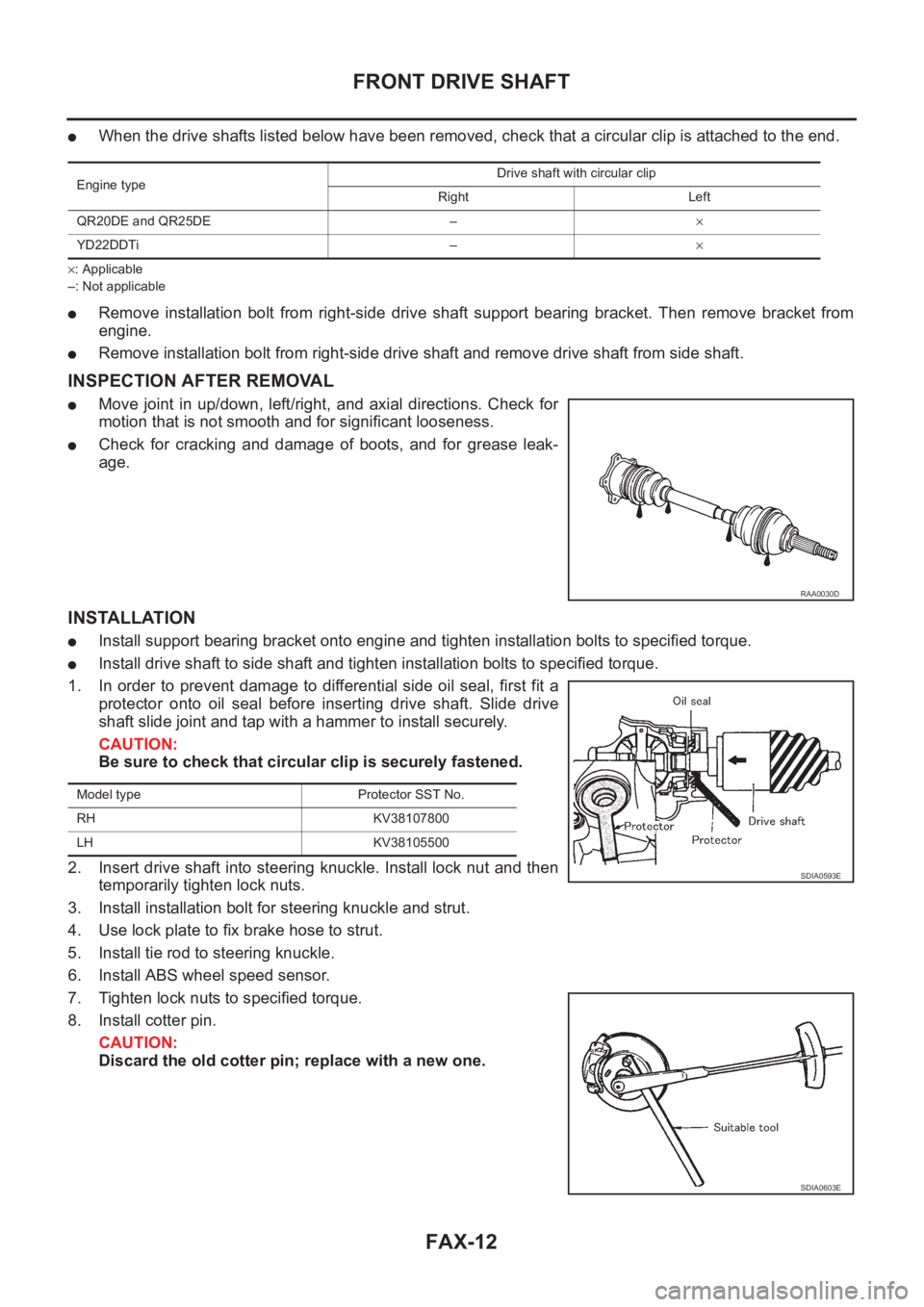
●Move joint in up/down, left/right, and axial directions. Check for
motion that is not smooth and for significant looseness.
●Check for cracking and damage of boots, and for grease leak-
age.
INSTALLATION
●Install support bearing bracket onto engine and tighten installation bolts to specified torque.
●Install drive shaft to side shaft and tighten installation bolts to specified torque.
1. In order to prevent damage to differential side oil seal, first fit a
protector onto oil seal before inserting drive shaft. Slide drive
shaft slide joint and tap with a hammer to install securely.
CAUTION:
Be sure to check that circular clip is securely fastened.
2. Insert drive shaft into steering knuckle. Install lock nut and then
temporarily tighten lock nuts.
3. Install installation bolt for steering knuckle and strut.
4. Use lock plate to fix brake hose to strut.
5. Install tie rod to steering knuckle.
6. Install ABS wheel speed sensor.
7. Tighten lock nuts to specified torque.
8. Install cotter pin.
CAUTION:
Discard the old cotter pin; replace with a new one.
Engine typeDrive shaft with circular clip
Right Left
QR20DE and QR25DE –×
YD22DDTi –×
RAA0030D
Model type Protector SST No.
RH KV38107800
LH KV38105500
SDIA0593E
SDIA0603E
Page 2964 of 3833
FAX-16
FRONT DRIVE SHAFT
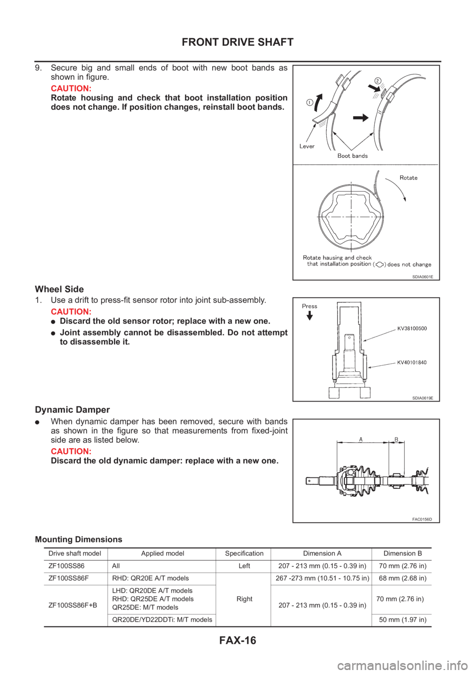
9. Secure big and small ends of boot with new boot bands as
shown in figure.
CAUTION:
Rotate housing and check that boot installation position
does not change. If position changes, reinstall boot bands.
Wheel Side
1. Use a drift to press-fit sensor rotor into joint sub-assembly.
CAUTION:
●Discard the old sensor rotor; replace with a new one.
●Joint assembly cannot be disassembled. Do not attempt
to disassemble it.
Dynamic Damper
●When dynamic damper has been removed, secure with bands
as shown in the figure so that measurements from fixed-joint
side are as listed below.
CAUTION:
Discard the old dynamic damper: replace with a new one.
Mounting Dimensions
SDIA0601E
SDIA0619E
FAC0156D
Drive shaft model Applied model Specification Dimension A Dimension B
ZF100SS86 All Left 207 - 213 mm (0.15 - 0.39 in) 70 mm (2.76 in)
ZF100SS86F RHD: QR20E A/T models
Right267 -273 mm (10.51 - 10.75 in) 68 mm (2.68 in)
ZF100SS86F+BLHD: QR20DE A/T models
RHD: QR25DE A/T models
QR25DE: M/T models207 - 213 mm (0.15 - 0.39 in)70 mm (2.76 in)
QR20DE/YD22DDTi: M/T models 50 mm (1.97 in)
Page 3005 of 3833
PRECAUTIONS
SRS-3
C
D
E
F
G
I
J
K
L
MA
B
SRS
PRECAUTIONSPFP:00001
Precautions for Supplemental Restraint System (SRS) “AIR BAG” and “SEAT
BELT PRE-TENSIONER”
EHS000QI
The Supplemental Restraint System such as “AIR BAG” and “SEAT BELT PRE-TENSIONER”, used along
with a front seat belt, helps to reduce the risk or severity of injury to the driver and front passenger for certain
types of collision. Information necessary to service the system safely is included in the SRS and SB section of
this Service Manual.
WARNING:
●To avoid rendering the SRS inoperative, which could increase the risk of personal injury or death
in the event of a collision which would result in air bag inflation, all maintenance must be per-
formed by an authorized NISSAN/INFINITI dealer.
●Improper maintenance, including incorrect removal and installation of the SRS, can lead to per-
sonal injury caused by unintentional activation of the system. For removal of Spiral Cable and Air
Bag Module, see the SRS section.
●Do not use electrical test equipment on any circuit related to the SRS unless instructed to in this
Service Manual. SRS wiring harnesses can be identified by yellow and/or orange harness connec-
tors.
Precautions for SRS “AIR BAG” and “SEAT BELT PRE-TENSIONER” ServiceEHS000BH
●Do not use electrical test equipment to check SRS circuits unless instructed to in this Service Manual.
●Before servicing the SRS, turn ignition switch “OFF”, disconnect both battery cables and wait at least 3
minutes.
For approximately 3 minutes after the cables is removed, it is still possible for the air bag and seat belt
pre-tensioner to deploy. Therefore, do not work on any SRS connectors or wires until at least 3 minutes
have passed.
●Diagnosis sensor unit must always be installed with their arrow marks “⇐” pointing towards the front of the
vehicle for proper operation. Also check diagnosis sensor unit for cracks, deformities or rust before instal-
lation and replace as required.
●The spiral cable must be aligned with the neutral position since its rotations are limited. Do not attempt to
turn steering wheel or column after removal of steering gear.
●Handle air bag module carefully. Always place driver and front passenger air bag modules with the pad
side facing upward and place front side air bag module standing with stud bolt side setting bottom.
●Conduct self-diagnosis to check entire SRS for proper function after replacing any components.
●After air bag inflates, the front instrument panel assembly should be replaced if damaged.
Trouble Diagnosis PrecautionEHS000BI
When you read wiring diagrams, refer to the followings:
●“HOW TO READ WIRING DIAGRAMS” in GI section
●PG-2, "POWER SUPPLY ROUTING" in PG section
When you perform trouble diagnosis, refer to the followings:
●“HOW TO FOLLOW TEST GROUP IN TROUBLE DIAGNOSIS” in GI section
●“HOW TO PERFORM EFFICIENT DIAGNOSIS FOR AN ELECTRICAL INCIDENT” in GI section
Check for any service bulletins before servicing the vehicle.
Page 3016 of 3833
![NISSAN X-TRAIL 2001 Service Repair Manual SRS-14
TROUBLE DIAGNOSIS
CONSULT-II Function
EHS000O6
DIAGNOSIS MODE FOR CONSULT-II
●“SELF-DIAG [CURRENT]”
A current Self-diagnosis result (also indicated by the number of warning lam NISSAN X-TRAIL 2001 Service Repair Manual SRS-14
TROUBLE DIAGNOSIS
CONSULT-II Function
EHS000O6
DIAGNOSIS MODE FOR CONSULT-II
●“SELF-DIAG [CURRENT]”
A current Self-diagnosis result (also indicated by the number of warning lam](/manual-img/5/57405/w960_57405-3015.png)
SRS-14
TROUBLE DIAGNOSIS
CONSULT-II Function
EHS000O6
DIAGNOSIS MODE FOR CONSULT-II
●“SELF-DIAG [CURRENT]”
A current Self-diagnosis result (also indicated by the number of warning lamp flashes in the Diagnosis
mode) is displayed on the CONSULT-II screen in real time. This refers to a malfunctioning part requiring
repairs.
●“SELF-DIAG [PAST]”
Diagnosis results previously stored in the memory are displayed on the CONSULT-II screen. The stored
results are not erased until memory erasing is executed.
●“TROUBLE DIAG RECORD”
With TROUBLE DIAG RECORD, diagnosis results previously erased by a reset operation can be dis-
played on the CONSULT-II screen.
●“ECU DISCRIMINATED NO.”
The diagnosis sensor unit for each vehicle model is assigned with its own, individual classification num-
ber. Refer to SRS-40, "
ECU DISCRIMINATED NO." This number will be displayed on the CONSULT-II
screen. When replacing the diagnosis sensor unit, refer to the part number for the compatibility. After
installation, replacement with a correct unit can be checked by confirming this classification number on the
CONSULT-II screen.
HOW TO CHANGE SELF-DIAGNOSIS MODE WITH CONSULT-II
From User Mode to Diagnosis Mode
After selecting “AIR BAG” on the “SELECT SYSTEM” screen, User mode automatically changes to Diagnosis
mode.
From Diagnosis Mode to User Mode
To return to User mode from Diagnosis mode, touch “BACK” key of CONSULT-II until “SELECT SYSTEM”
appears, Diagnosis mode automatically changes to User mode.
SRS803
SRS804
Page 3078 of 3833
BL-26
POWER DOOR LOCK SYSTEM
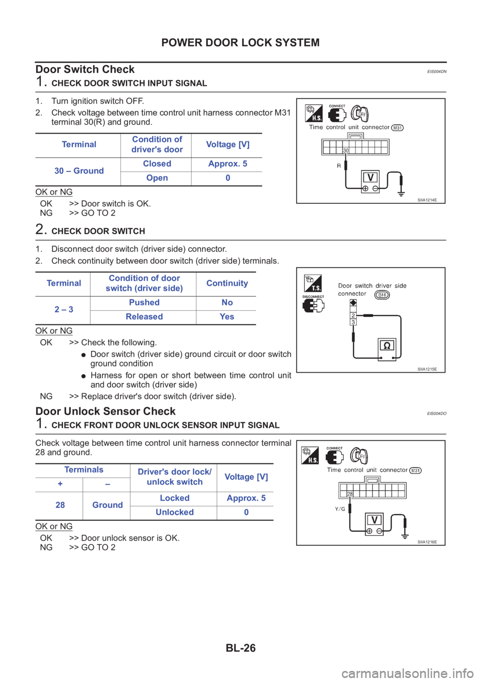
Door Switch Check
EIS004DN
1. CHECK DOOR SWITCH INPUT SIGNAL
1. Turn ignition switch OFF.
2. Check voltage between time control unit harness connector M31
terminal 30(R) and ground.
OK or NG
OK >> Door switch is OK.
NG >> GO TO 2
2. CHECK DOOR SWITCH
1. Disconnect door switch (driver side) connector.
2. Check continuity between door switch (driver side) terminals.
OK or NG
OK >> Check the following.
●Door switch (driver side) ground circuit or door switch
ground condition
●Harness for open or short between time control unit
and door switch (driver side)
NG >> Replace driver's door switch (driver side).
Door Unlock Sensor CheckEIS004DO
1. CHECK FRONT DOOR UNLOCK SENSOR INPUT SIGNAL
Check voltage between time control unit harness connector terminal
28 and ground.
OK or NG
OK >> Door unlock sensor is OK.
NG >> GO TO 2Te r m i n a lCondition of
driver's doorVoltage [V]
30 – GroundClosed Approx. 5
Open 0
SIIA1214E
Te r m i n a lCondition of door
switch (driver side)Continuity
2 – 3Pushed No
Released Yes
SIIA1215E
Te r m i n a l s
Driver's door lock/
unlock switchVoltage [V]
+–
28 GroundLocked Approx. 5
Unlocked 0
SIIA1216E