2001 NISSAN X-TRAIL air filter
[x] Cancel search: air filterPage 3279 of 3833
ATC-3
C
D
E
F
G
H
I
K
L
MA
B
AT C Removal and Installation ....................................... 116
REMOVAL .......................................................... 116
INSTALLATION .................................................. 116
Disassembly and Assembly .................................. 117
BLOWER MOTOR ...................................................118
Removal and Installation ....................................... 118
INTAKE DOOR MOTOR ..........................................119
Removal and Installation ....................................... 119
FAN CONTROL AMPLIFIER .................................. 120
Removal and Installation ...................................... 120
VENTILATION AIR FILTER .................................... 121
Removal and Installation ...................................... 121
FUNCTION ........................................................ 121
REPLACEMENT TIMING .................................. 121
REPLACEMENT AND PROCEDURES ............ 121
CLEANING ....................................................... . 121
HEATER & COOLING UNIT ASSEMBLY .............. 122
Removal and Installation ...................................... 122
REMOVAL ......................................................... 122
INSTALLATION ................................................. 123
Disassembly and Assembly ................................. 123
MODE DOOR MOTOR ........................................... 124
Removal and Installation ...................................... 124
AIR MIX DOOR MOTOR ......................................... 125
Removal and Installation ...................................... 125
HEATER CORE ...................................................... 126
Removal and Installation ...................................... 126
DUCTS AND GRILLES .......................................... 127
Removal and Installation ...................................... 127
VENTILATOR DUCT, DEFROSTER NOZZLE
AND DEFROSTER DUCTS .............................. 127
CENTER VENTILATOR GRILLE ...................... 127
SIDE VENTILATOR GRILLE ............................. 127
FOOT DUCT ..................................................... 128
FLOOR DUCT ................................................... 128
REFRIGERANT LINES ........................................... 129
HFC-134a (R-134a) Service Procedure ............... 129
SETTING OF SERVICE TOOLS AND EQUIP-
MENT ................................................................ 129
Components ......................................................... 131
WITH GASOLINE ENGINE ............................... 131
WITH DIESEL ENGINE .................................... 132
Removal and Installation for Compressor ............ 132REMOVAL .........................................................132
INSTALLATION .................................................134
Removal and Installation for Compressor Clutch . 135
REMOVAL .........................................................135
INSTALLATION .................................................138
Removal and Installation for Low-pressure flexible
hose ......................................................................141
REMOVAL .........................................................141
INSTALLATION .................................................141
Removal and Installation for High-pressure flexible
hose ......................................................................142
REMOVAL .........................................................142
INSTALLATION .................................................142
Removal and Installation for High-pressure pipe ..142
REMOVAL .........................................................142
INSTALLATION .................................................142
Removal and Installation for Refrigerant Pressure
Sensor ..................................................................143
Removal and Installation for Dual-pressure Switch .143
Removal and Installation for Condenser ..............143
REMOVAL .........................................................143
INSTALLATION .................................................144
Removal and Installation for Evaporator ..............145
REMOVAL .........................................................145
INSTALLATION .................................................145
Removal and Installation for Expansion Valve ......146
Removal and Installation for Liquid Tank ..............146
REMOVAL .........................................................146
INSTALLATION .................................................146
Checking for Refrigerant Leaks ............................146
Checking System for Leaks Using the Fluorescent
Leak Detector .......................................................147
Dye Injection .........................................................147
Electronic Refrigerant Leak Detector ....................147
PRECAUTIONS FOR HANDLING LEAK
DETECTOR .......................................................147
CHECKING PROCEDURE ...............................148
SERVICE DATA AND SPECIFICATIONS (SDS) ....150
COMPRESSOR ....................................................150
LUBRICANT .........................................................150
REFRIGERANT ....................................................150
ENGINE IDLING SPEED ......................................150
BELT TENSION ................................................... .150
Page 3393 of 3833
BLOWER UNIT
ATC-117
C
D
E
F
G
H
I
K
L
MA
B
AT C
Disassembly and AssemblyEJS000UM
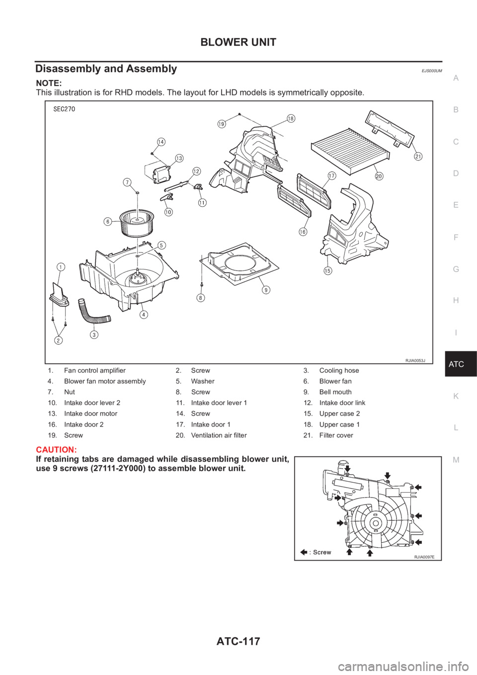
NOTE:
This illustration is for RHD models. The layout for LHD models is symmetrically opposite.
CAUTION:
If retaining tabs are damaged while disassembling blower unit,
use 9 screws (27111-2Y000) to assemble blower unit.
1. Fan control amplifier 2. Screw 3. Cooling hose
4. Blower fan motor assembly 5. Washer 6. Blower fan
7. Nut 8. Screw 9. Bell mouth
10. Intake door lever 2 11. Intake door lever 1 12. Intake door link
13. Intake door motor 14. Screw 15. Upper case 2
16. Intake door 2 17. Intake door 1 18. Upper case 1
19. Screw 20. Ventilation air filter 21. Filter cover
RJIA0053J
RJIA0097E
Page 3397 of 3833
VENTILATION AIR FILTER
ATC-121
C
D
E
F
G
H
I
K
L
MA
B
AT C
VENTILATION AIR FILTER PFP:27277
Removal and InstallationEJS000UP
FUNCTION
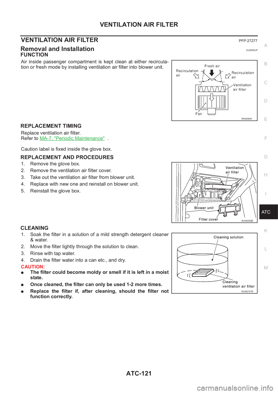
Air inside passenger compartment is kept clean at either recircula-
tion or fresh mode by installing ventilation air filter into blower unit.
REPLACEMENT TIMING
Replace ventilation air filter.
Refer to MA-7, "
Periodic Maintenance" .
Caution label is fixed inside the glove box.
REPLACEMENT AND PROCEDURES
1. Remove the glove box.
2. Remove the ventilation air filter cover.
3. Take out the ventilation air filter from blower unit.
4. Replace with new one and reinstall on blower unit.
5. Reinstall the glove box.
CLEANING
1. Soak the filter in a solution of a mild strength detergent cleaner
& water.
2. Move the filter lightly through the solution to clean.
3. Rinse with tap water.
4. Drain the filter water into a can etc., and dry.
CAUTION:
●The filter could become moldy or smell if it is left in a moist
state.
●Once cleaned, the filter can only be used 1-2 more times.
●Replace the filter if, after cleaning, should the filter not
function correctly.
RHA680H
RJIA0058E
RJIA0747E
Page 3577 of 3833
COMBINATION METERS (LHD MODELS)
DI-19
C
D
E
F
G
H
I
J
L
MA
B
DI
The Fuel Gauge Does Not Move to Full-position.EKS002ZK
1.QUESTION 1
Does it take a long time for the pointer to move to Full-position?
Ye s o r N o
Ye s > > G O T O 2 .
No >> GO TO 3.
2.QUESTION 2
Was the vehicle fueled with the ignition switch ON?
Ye s o r N o
Yes >> Be sure to fuel the vehicle with the ignition switch OFF. Otherwise it will take a long time to move
to Full-position because of the characteristic of the fuel gauge.
No >> GO TO 3.
3.QUESTION 3
Is the floor or the vehicle inclined?
Ye s o r N o
Yes >> It may not be filled fully.
No >> GO TO 4.
4.QUESTION 4
During driving, does the fuel gauge pointer move gradually toward E-position?
Ye s o r N o
Yes >> Check the components. Refer to DI-21, "Electrical Components Inspection" .
No >> The float arm may interfere or bind with any of the components in the fuel tank.
The Fuel Gauge Does Not Work.EKS002ZL
1.HARNESS CONNECTOR INSPECTION
1. Turn the ignition switch OFF.
2. Check combination meter, fuel level sensor unit, sub fuel level sensor unit and terminals (meter-side,
module-side, and harness-side) for poor connection and bend.
OK or NG
OK >> GO TO 2.
NG >> Repair connector.
2. CHECK INSTALLATION CONDITION
Check fuel level sensor unit or sub fuel level sensor unit installation (refer toFL-4, "
FUEL LEVEL SENSOR
UNIT, FUEL FILTER AND FUEL PUMP ASSEMBLY" for QR engine models or FL-17, "FUEL LEVEL SEN-
SOR UNIT" for YD engine models), and check whether the float arm interferes or binds with any components
inside the arm.
OK or NG
OK >> Fuel level sensor unit is OK.
NG >> Check fuel level sensor unit or sub fuel level sensor unit. Refer to DI-21, "
Electrical Components
Inspection" .
Page 3597 of 3833
COMBINATION METERS (RHD MODELS)
DI-39
C
D
E
F
G
H
I
J
L
MA
B
DI
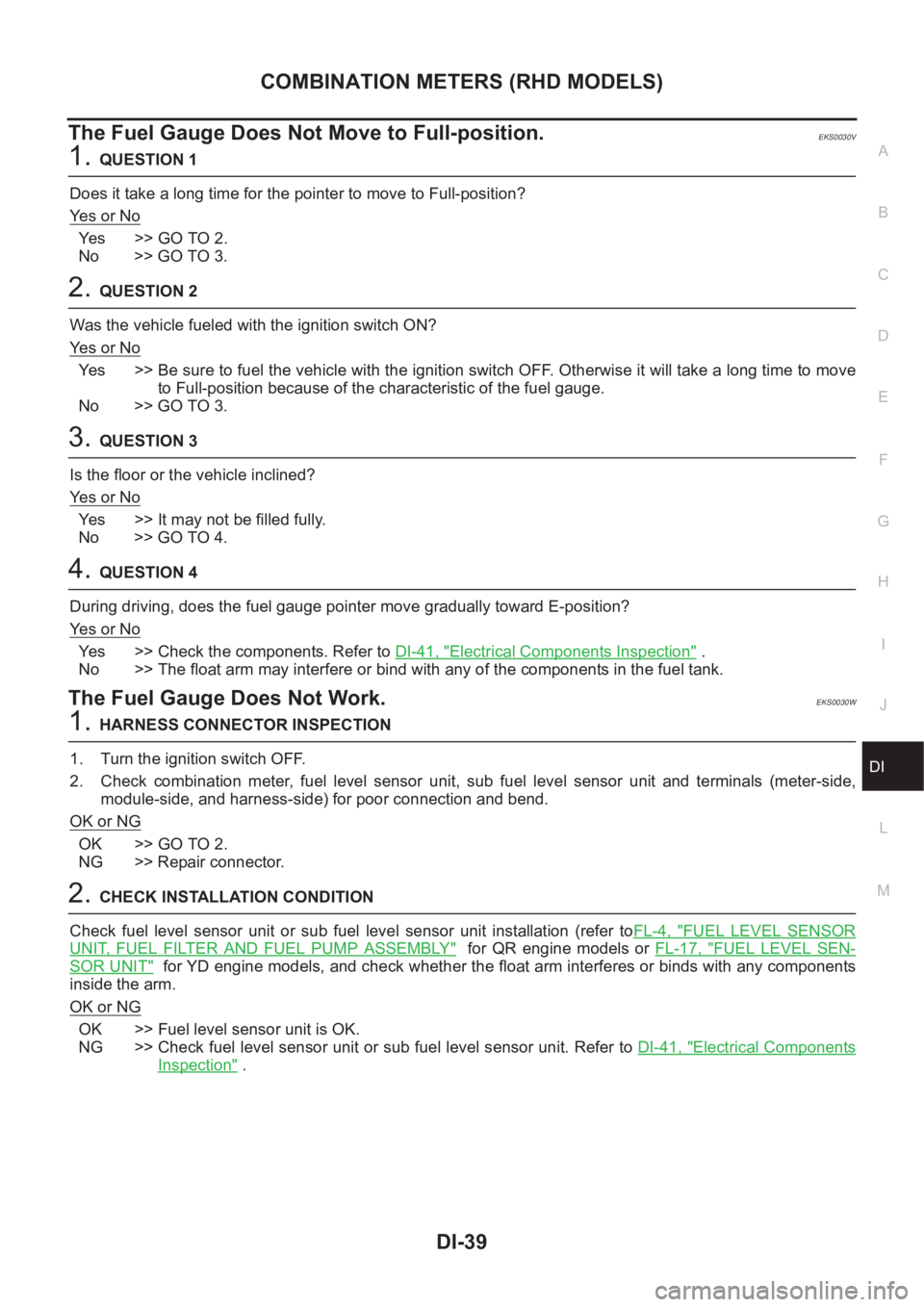
The Fuel Gauge Does Not Move to Full-position.EKS0030V
1.QUESTION 1
Does it take a long time for the pointer to move to Full-position?
Ye s o r N o
Ye s > > G O T O 2 .
No >> GO TO 3.
2.QUESTION 2
Was the vehicle fueled with the ignition switch ON?
Ye s o r N o
Yes >> Be sure to fuel the vehicle with the ignition switch OFF. Otherwise it will take a long time to move
to Full-position because of the characteristic of the fuel gauge.
No >> GO TO 3.
3.QUESTION 3
Is the floor or the vehicle inclined?
Ye s o r N o
Yes >> It may not be filled fully.
No >> GO TO 4.
4.QUESTION 4
During driving, does the fuel gauge pointer move gradually toward E-position?
Ye s o r N o
Yes >> Check the components. Refer to DI-41, "Electrical Components Inspection" .
No >> The float arm may interfere or bind with any of the components in the fuel tank.
The Fuel Gauge Does Not Work.EKS0030W
1.HARNESS CONNECTOR INSPECTION
1. Turn the ignition switch OFF.
2. Check combination meter, fuel level sensor unit, sub fuel level sensor unit and terminals (meter-side,
module-side, and harness-side) for poor connection and bend.
OK or NG
OK >> GO TO 2.
NG >> Repair connector.
2.CHECK INSTALLATION CONDITION
Check fuel level sensor unit or sub fuel level sensor unit installation (refer toFL-4, "
FUEL LEVEL SENSOR
UNIT, FUEL FILTER AND FUEL PUMP ASSEMBLY" for QR engine models or FL-17, "FUEL LEVEL SEN-
SOR UNIT" for YD engine models, and check whether the float arm interferes or binds with any components
inside the arm.
OK or NG
OK >> Fuel level sensor unit is OK.
NG >> Check fuel level sensor unit or sub fuel level sensor unit. Refer to DI-41, "
Electrical Components
Inspection" .
Page 3781 of 3833
MA-1
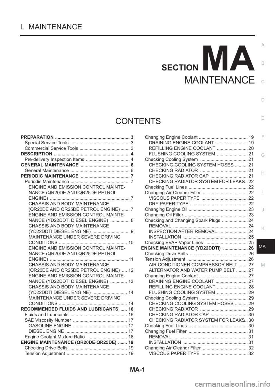
MAINTENANCE
L MAINTENANCE
CONTENTS
C
D
E
F
G
H
I
J
K
M
SECTION
A
B
MA
MAINTENANCE
PREPARATION ........................................................... 3
Special Service Tools ............................................... 3
Commercial Service Tools ........................................ 3
DESCRIPTION ............................................................ 4
Pre-delivery Inspection Items ................................... 4
GENERAL MAINTENANCE ....................................... 6
General Maintenance ............................................... 6
PERIODIC MAINTENANCE ....................................... 7
Periodic Maintenance ............................................... 7
ENGINE AND EMISSION CONTROL MAINTE-
NANCE (QR20DE AND QR25DE PETROL
ENGINE) ............................................................... 7
CHASSIS AND BODY MAINTENANCE
(QR20DE AND QR25DE PETROL ENGINE) ....... 7
ENGINE AND EMISSION CONTROL MAINTE-
NANCE (YD22DDTI DIESEL ENGINE) ................ 8
CHASSIS AND BODY MAINTENANCE
(YD22DDTI DIESEL ENGINE) .............................. 9
MAINTENANCE UNDER SEVERE DRIVING
CONDITIONS ...................................................... 10
ENGINE AND EMISSION CONTROL MAINTE-
NANCE (QR20DE AND QR25DE PETROL
ENGINE) .............................................................. 11
CHASSIS AND BODY MAINTENANCE
(QR20DE AND QR25DE PETROL ENGINE) ..... 12
ENGINE AND EMISSION CONTROL MAINTE-
NANCE (YD22DDTI DIESEL ENGINE) .............. 13
CHASSIS AND BODY MAINTENANCE
(YD22DDTI DIESEL ENGINE) ............................ 14
MAINTENANCE UNDER SEVERE DRIVING
CONDITIONS ...................................................... 14
RECOMMENDED FLUIDS AND LUBRICANTS ...... 16
Fluids and Lubricants ............................................. 16
SAE Viscosity Number ........................................... 17
GASOLINE ENGINE ........................................... 17
DIESEL ENGINE ................................................. 17
Engine Coolant Mixture Ratio ................................ 18
ENGINE MAINTENANCE (QR20DE·QR25DE) ........ 19
Checking Drive Belts .............................................. 19
Tension Adjustment ................................................ 19Changing Engine Coolant ....................................... 19
DRAINING ENGINE COOLANT .......................... 19
REFILLING ENGINE COOLANT ......................... 20
FLUSHING COOLING SYSTEM ......................... 21
Checking Cooling System ...................................... 21
CHECKING COOLING SYSTEM HOSES ........... 21
CHECKING RADIATOR ...................................... 21
CHECKING RADIATOR CAP .............................. 21
CHECKING RADIATOR SYSTEM FOR LEAKS ... 22
Checking Fuel Lines ............................................ ... 22
Changing Air Cleaner Filter .................................... 22
VISCOUS PAPER TYPE ..................................... 22
DRY PAPER TYPE .............................................. 22
Changing Engine Oil ............................................ ... 23
Changing Oil Filter .................................................. 23
Checking and Changing Spark Plugs ..................... 24
REMOVAL ........................................................... 24
INSPECTION AFTER REMOVAL ....................... 24
INSTALLATION ................................................... 25
Checking EVAP Vapor Lines .................................. 25
ENGINE MAINTENANCE (YD22DDTI) .................... 26
Checking Drive Belts .............................................. 26
Tension Adjustment ............................................. ... 26
AIR CONDITIONER COMPRESSOR BELT ........ 27
ALTERNATOR AND WATER PUMP BELT .......... 27
Changing Engine Coolant ....................................... 27
DRAINING ENGINE COOLANT .......................... 27
REFILLING ENGINE COOLANT ......................... 28
FLUSHING COOLING SYSTEM ......................... 29
Checking Cooling System ...................................... 29
CHECKING COOLING SYSTEM HOSES ........... 29
CHECKING RADIATOR ...................................... 29
CHECKING RADIATOR CAP .............................. 30
CHECKING RADIATOR SYSTEM FOR LEAKS ... 30
Checking Fuel Lines ............................................ ... 30
Changing Fuel Filter ............................................... 31
REMOVAL ........................................................... 31
INSTALLATION ................................................... 31
Changing Air Cleaner Filter .................................... 32
VISCOUS PAPER TYPE ..................................... 32
Page 3784 of 3833
MA-4
DESCRIPTION
DESCRIPTION
PFP:00000
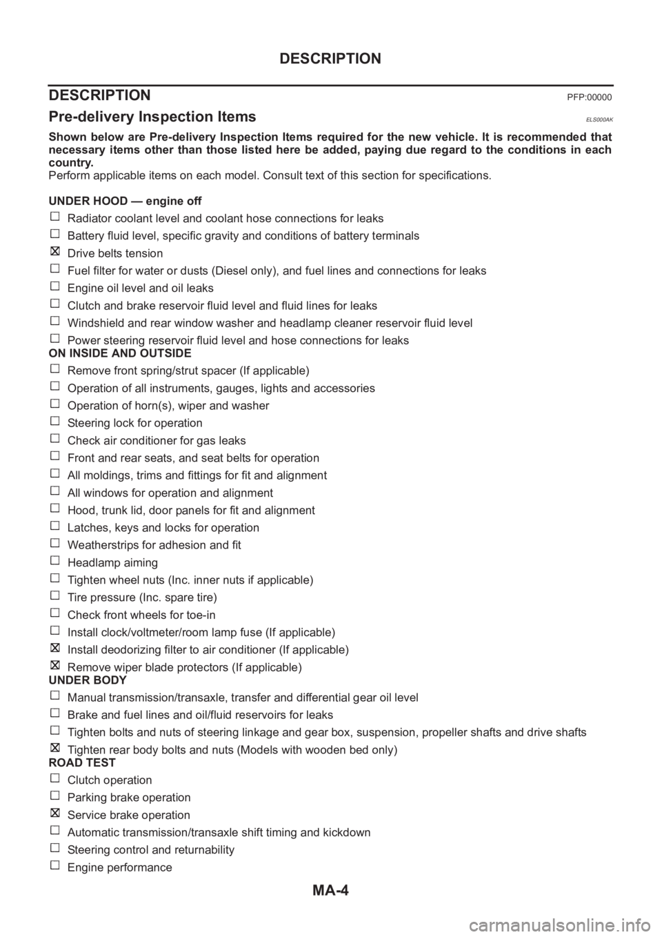
Pre-delivery Inspection ItemsELS000AK
Shown below are Pre-delivery Inspection Items required for the new vehicle. It is recommended that
necessary items other than those listed here be added, paying due regard to the conditions in each
country.
Perform applicable items on each model. Consult text of this section for specifications.
UNDER HOOD — engine off
Radiator coolant level and coolant hose connections for leaks
Battery fluid level, specific gravity and conditions of battery terminals
Drive belts tension
Fuel filter for water or dusts (Diesel only), and fuel lines and connections for leaks
Engine oil level and oil leaks
Clutch and brake reservoir fluid level and fluid lines for leaks
Windshield and rear window washer and headlamp cleaner reservoir fluid level
Power steering reservoir fluid level and hose connections for leaks
ON INSIDE AND OUTSIDE
Remove front spring/strut spacer (If applicable)
Operation of all instruments, gauges, lights and accessories
Operation of horn(s), wiper and washer
Steering lock for operation
Check air conditioner for gas leaks
Front and rear seats, and seat belts for operation
All moldings, trims and fittings for fit and alignment
All windows for operation and alignment
Hood, trunk lid, door panels for fit and alignment
Latches, keys and locks for operation
Weatherstrips for adhesion and fit
Headlamp aiming
Tighten wheel nuts (Inc. inner nuts if applicable)
Tire pressure (Inc. spare tire)
Check front wheels for toe-in
Install clock/voltmeter/room lamp fuse (If applicable)
Install deodorizing filter to air conditioner (If applicable)
Remove wiper blade protectors (If applicable)
UNDER BODY
Manual transmission/transaxle, transfer and differential gear oil level
Brake and fuel lines and oil/fluid reservoirs for leaks
Tighten bolts and nuts of steering linkage and gear box, suspension, propeller shafts and drive shafts
Tighten rear body bolts and nuts (Models with wooden bed only)
ROAD TEST
Clutch operation
Parking brake operation
Service brake operation
Automatic transmission/transaxle shift timing and kickdown
Steering control and returnability
Engine performance
Page 3787 of 3833
PERIODIC MAINTENANCE
MA-7
C
D
E
F
G
H
I
J
K
MA
B
MA
PERIODIC MAINTENANCEPFP:00026
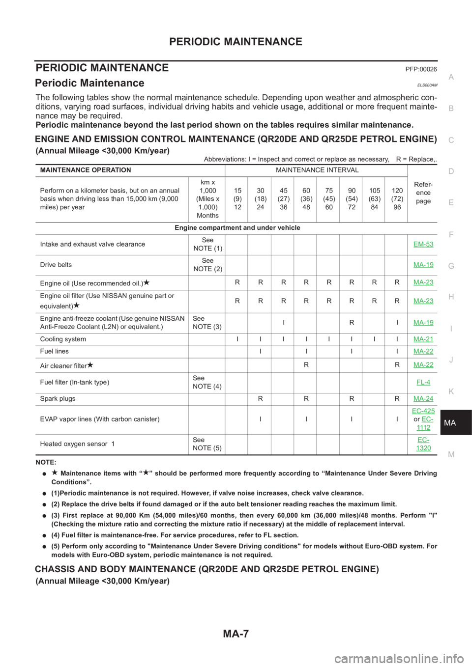
Periodic MaintenanceELS000AM
The following tables show the normal maintenance schedule. Depending upon weather and atmospheric con-
ditions, varying road surfaces, individual driving habits and vehicle usage, additional or more frequent mainte-
nance may be required.
Periodic maintenance beyond the last period shown on the tables requires similar maintenance.
ENGINE AND EMISSION CONTROL MAINTENANCE (QR20DE AND QR25DE PETROL ENGINE)
(Annual Mileage <30,000 Km/year)
Abbreviations: I = Inspect and correct or replace as necessary,R = Replace,.
NOTE:
● Maintenance items with “ ” should be performed more frequently according to “Maintenance Under Severe Driving
Conditions”.
●(1)Periodic maintenance is not required. However, if valve noise increases, check valve clearance.
●(2) Replace the drive belts if found damaged or if the auto belt tensioner reading reaches the maximum limit.
●(3) First replace at 90,000 Km (54,000 miles)/60 months, then every 60,000 km (36,000 miles)/48 months. Perform "I"
(Checking the mixture ratio and correcting the mixture ratio if necessary) at the middle of replacement interval.
●(4) Fuel filter is maintenance-free. For service procedures, refer to FL section.
●(5) Perform only according to "Maintenance Under Severe Driving conditions" for models without Euro-OBD system. For
models with Euro-OBD system, periodic maintenance is not required.
CHASSIS AND BODY MAINTENANCE (QR20DE AND QR25DE PETROL ENGINE)
(Annual Mileage <30,000 Km/year)
MAINTENANCE OPERATIONMAINTENANCE INTERVAL
Refer-
ence
page Perform on a kilometer basis, but on an annual
basis when driving less than 15,000 km (9,000
miles) per yearkm x
1,000
(Miles x
1,000)
Months15
(9)
1230
(18)
2445
(27)
3660
(36)
4875
(45)
6090
(54)
72105
(63)
84120
(72)
96
Engine compartment and under vehicle
Intake and exhaust valve clearanceSee
NOTE (1)EM-53
Drive beltsSee
NOTE (2)MA-19
Engine oil (Use recommended oil.)R RRRRRRRMA-23
Engine oil filter (Use NISSAN genuine part or
equivalent)R RRRRRRRMA-23
Engine anti-freeze coolant (Use genuine NISSAN
Anti-Freeze Coolant (L2N) or equivalent.)See
NOTE (3)IRIMA-19
Cooling system II IIIIIIMA-21
Fuel lines I I I IMA-22
Air cleaner filterRRMA-22
Fuel filter (In-tank type)See
NOTE (4)FL-4
Spark plugs R R R RMA-24
EVAP vapor lines (With carbon canister) I I I IEC-425or EC-
111 2
Heated oxygen sensor 1 See
NOTE (5)EC-1320