2001 NISSAN X-TRAIL air filter
[x] Cancel search: air filterPage 3796 of 3833
MA-16
RECOMMENDED FLUIDS AND LUBRICANTS
RECOMMENDED FLUIDS AND LUBRICANTS
PFP:00000
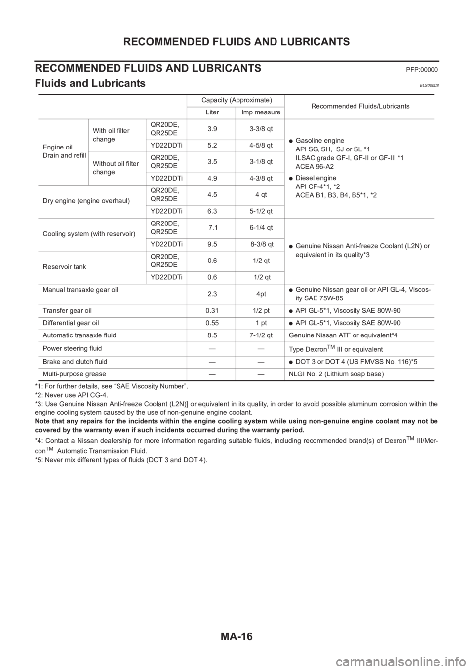
Fluids and LubricantsELS000C8
*1: For further details, see “SAE Viscosity Number”.
*2: Never use API CG-4.
*3: Use Genuine Nissan Anti-freeze Coolant (L2N)] or equivalent in its quality, in order to avoid possible aluminum corrosion within the
engine cooling system caused by the use of non-genuine engine coolant.
Note that any repairs for the incidents within the engine cooling system while using non-genuine engine coolant may not be
covered by the warranty even if such incidents occurred during the warranty period.
*4: Contact a Nissan dealership for more information regarding suitable fluids, including recommended brand(s) of Dexron
TM III/Mer-
conTM Automatic Transmission Fluid.
*5: Never mix different types of fluids (DOT 3 and DOT 4).Capacity (Approximate)
Recommended Fluids/Lubricants
Liter Imp measure
Engine oil
Drain and refillWith oil filter
changeQR20DE,
QR25DE3.9 3-3/8 qt
●Gasoline engine
API SG, SH, SJ or SL *1
ILSAC grade GF-I, GF-II or GF-III *1
ACEA 96-A2
●Diesel engine
API CF-4*1, *2
ACEA B1, B3, B4, B5*1, *2 YD22DDTi 5.2 4-5/8 qt
Without oil filter
changeQR20DE,
QR25DE3.5 3-1/8 qt
YD22DDTi 4.9 4-3/8 qt
Dry engine (engine overhaul)QR20DE,
QR25DE4.5 4 qt
YD22DDTi 6.3 5-1/2 qt
Cooling system (with reservoir)QR20DE,
QR25DE 7.1 6-1/4 qt
●Genuine Nissan Anti-freeze Coolant (L2N) or
equivalent in its quality*3 YD22DDTi 9.5 8-3/8 qt
Reservoir tankQR20DE,
QR25DE0.6 1/2 qt
YD22DDTi 0.6 1/2 qt
Manual transaxle gear oil
2.3 4pt
●Genuine Nissan gear oil or API GL-4, Viscos-
ity SAE 75W-85
Transfer gear oil 0.31 1/2 pt
●API GL-5*1, Viscosity SAE 80W-90
Differential gear oil 0.55 1 pt
●API GL-5*1, Viscosity SAE 80W-90
Automatic transaxle fluid 8.5 7-1/2 qt Genuine Nissan ATF or equivalent*4
Power steering fluid — —
Type Dexron
TM III or equivalent
Brake and clutch fluid — —
●DOT 3 or DOT 4 (US FMVSS No. 116)*5
Multi-purpose grease — — NLGI No. 2 (Lithium soap base)
Page 3802 of 3833
MA-22
ENGINE MAINTENANCE (QR20DE·QR25DE)
●Replace the radiator cap if there is an abnormality in the negative-pressure valve, or if the open-valve
pressure is outside of the standard values.
CHECKING RADIATOR SYSTEM FOR LEAKS
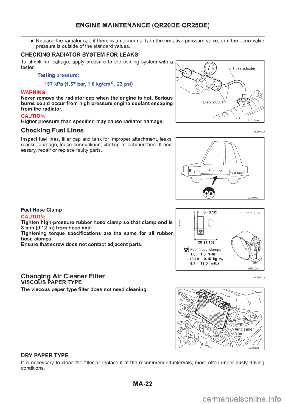
To check for leakage, apply pressure to the cooling system with a
tester.
WARNING:
Never remove the radiator cap when the engine is hot. Serious
burns could occur from high pressure engine coolant escaping
from the radiator.
CAUTION:
Higher pressure than specified may cause radiator damage.
Checking Fuel LinesELS000JX
Inspect fuel lines, filler cap and tank for improper attachment, leaks,
cracks, damage, loose connections, chafing or deterioration. If nec-
essary, repair or replace faulty parts.
Fuel Hose Clamp
CAUTION:
Tighten high-pressure rubber hose clamp so that clamp end is
3 mm (0.12 in) from hose end.
Tightening torque specifications are the same for all rubber
hose clamps.
Ensure that screw does not contact adjacent parts.
Changing Air Cleaner FilterELS000JY
VISCOUS PAPER TYPE
The viscous paper type filter does not need cleaning.
DRY PAPER TYPE
It is necessary to clean the filter or replace it at the recommended intervals, more often under dusty driving
conditions.Testing pressure:
157 kPa (1.57 bar, 1.6 kg/cm
2 , 23 psi)
SLC756AA
SMA803A
MMA104A
SMA037D
Page 3811 of 3833
ENGINE MAINTENANCE (YD22DDTI)
MA-31
C
D
E
F
G
H
I
J
K
MA
B
MA
Changing Fuel FilterELS000CF
REMOVAL
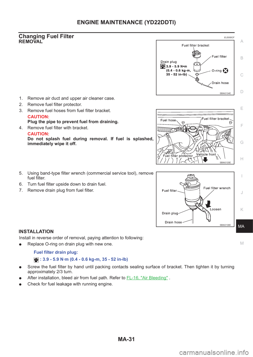
1. Remove air duct and upper air cleaner case.
2. Remove fuel filter protector.
3. Remove fuel hoses from fuel filter bracket.
CAUTION:
Plug the pipe to prevent fuel from draining.
4. Remove fuel filter with bracket.
CAUTION:
Do not splash fuel during removal. If fuel is splashed,
immediately wipe it off.
5. Using band-type filter wrench (commercial service tool), remove
fuel filter.
6. Turn fuel filter upside down to drain fuel.
7. Remove drain plug from fuel filter.
INSTALLATION
Install in reverse order of removal, paying attention to following:
●Replace O-ring on drain plug with new one.
●Screw the fuel filter by hand until packing contacts sealing surface of bracket. Then tighten it by turning
approximately 2/3 turn.
●After installation, bleed air from fuel path. Refer to FL-16, "Air Bleeding" .
●Check for fuel leakage with running engine.
SBIA0134E
SBIA0135E
SBIA0136E
Fuel filter drain plug:
: 3.9 - 5.9 N·m (0.4 - 0.6 kg-m, 35 - 52 in-lb)
Page 3812 of 3833
MA-32
ENGINE MAINTENANCE (YD22DDTI)
Changing Air Cleaner Filter
ELS000CG
VISCOUS PAPER TYPE
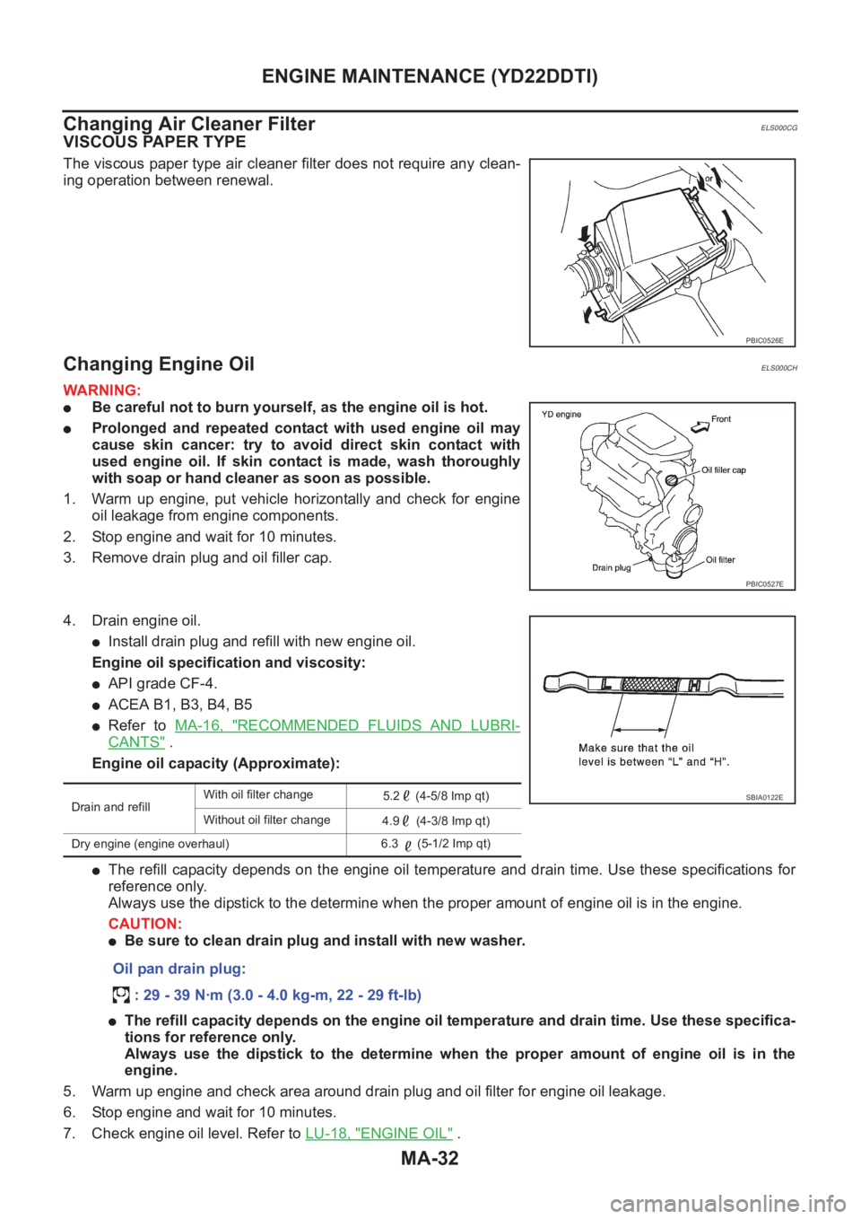
The viscous paper type air cleaner filter does not require any clean-
ing operation between renewal.
Changing Engine OilELS000CH
WARNING:
●Be careful not to burn yourself, as the engine oil is hot.
●Prolonged and repeated contact with used engine oil may
cause skin cancer: try to avoid direct skin contact with
used engine oil. If skin contact is made, wash thoroughly
with soap or hand cleaner as soon as possible.
1. Warm up engine, put vehicle horizontally and check for engine
oil leakage from engine components.
2. Stop engine and wait for 10 minutes.
3. Remove drain plug and oil filler cap.
4. Drain engine oil.
●Install drain plug and refill with new engine oil.
Engine oil specification and viscosity:
●API grade CF-4.
●ACEA B1, B3, B4, B5
●Refer to MA-16, "RECOMMENDED FLUIDS AND LUBRI-
CANTS" .
Engine oil capacity (Approximate):
●The refill capacity depends on the engine oil temperature and drain time. Use these specifications for
reference only.
Always use the dipstick to the determine when the proper amount of engine oil is in the engine.
CAUTION:
●Be sure to clean drain plug and install with new washer.
●The refill capacity depends on the engine oil temperature and drain time. Use these specifica-
tions for reference only.
Always use the dipstick to the determine when the proper amount of engine oil is in the
engine.
5. Warm up engine and check area around drain plug and oil filter for engine oil leakage.
6. Stop engine and wait for 10 minutes.
7. Check engine oil level. Refer to LU-18, "
ENGINE OIL" .
PBIC0526E
PBIC0527E
Drain and refillWith oil filter change
5.2 (4-5/8 Imp qt)
Without oil filter change
4.9 (4-3/8 Imp qt)
Dry engine (engine overhaul)6.3 (5-1/2 Imp qt)
Oil pan drain plug:
: 29 - 39 N·m (3.0 - 4.0 kg-m, 22 - 29 ft-lb)
SBIA0122E
Page 3814 of 3833
MA-34
ENGINE MAINTENANCE (YD22DDTI)
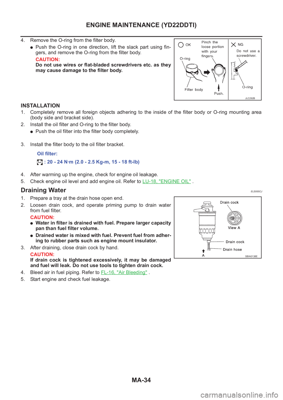
4. Remove the O-ring from the filter body.
●Push the O-ring in one direction, lift the slack part using fin-
gers, and remove the O-ring from the filter body.
CAUTION:
Do not use wires or flat-bladed screwdrivers etc. as they
may cause damage to the filter body.
INSTALLATION
1. Completely remove all foreign objects adhering to the inside of the filter body or O-ring mounting area
(body side and bracket side).
2. Install the oil filter and O-ring to the filter body.
●Push the oil filter into the filter body completely.
3. Install the filter body to the oil filter bracket.
4. After warming up the engine, check for engine oil leakage.
5. Check engine oil level and add engine oil. Refer to LU-18, "
ENGINE OIL" .
Draining WaterELS000CJ
1. Prepare a tray at the drain hose open end.
2. Loosen drain cock, and operate priming pump to drain water
from fuel filter.
CAUTION:
●Water in filter is drained with fuel. Prepare larger capacity
pan than fuel filter volume.
●Drained water is mixed with fuel. Prevent fuel from adher-
ing to rubber parts such as engine mount insulator.
3. After draining, close drain cock by hand.
CAUTION:
If drain cock is tightened excessively, it may be damaged
and fuel will leak. Do not use tools to tighten drain cock.
4. Bleed air in fuel piping. Refer to FL-16, "
Air Bleeding" .
5. Start engine and check fuel leakage.
JLC292B
Oil filter:
: 20 - 24 N·m (2.0 - 2.5 Kg-m, 15 - 18 ft-lb)
SBIA0138E
Page 3823 of 3833
SERVICE DATA AND SPECIFICATIONS (SDS)
MA-43
C
D
E
F
G
H
I
J
K
MA
B
MA
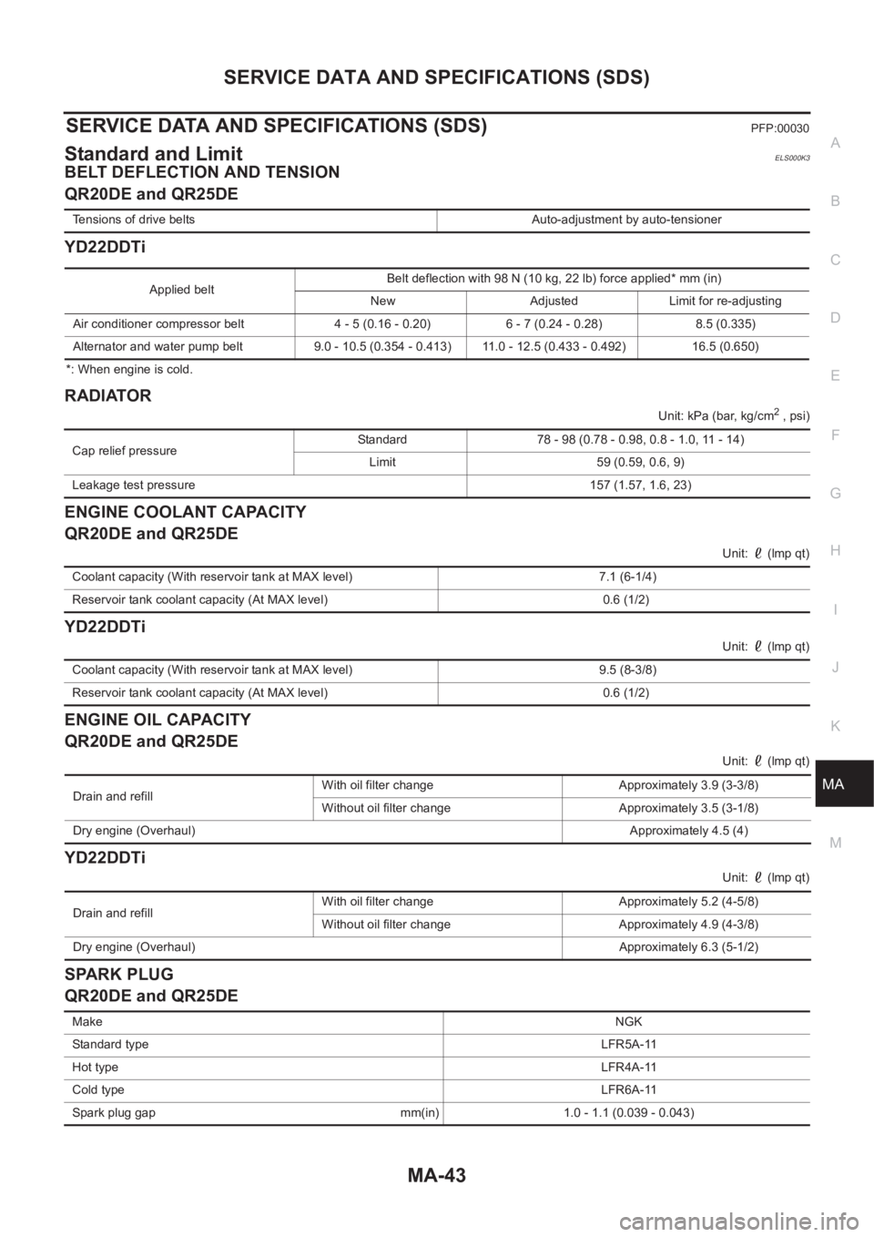
SERVICE DATA AND SPECIFICATIONS (SDS)PFP:00030
Standard and LimitELS000K3
BELT DEFLECTION AND TENSION
QR20DE and QR25DE
YD22DDTi
*: When engine is cold.
RADIATOR
Unit: kPa (bar, kg/cm2 , psi)
ENGINE COOLANT CAPACITY
QR20DE and QR25DE
Unit: (lmp qt)
YD22DDTi
Unit: (lmp qt)
ENGINE OIL CAPACITY
QR20DE and QR25DE
Unit: (lmp qt)
YD22DDTi
Unit: (lmp qt)
SPARK PLUG
QR20DE and QR25DE
Tensions of drive belts Auto-adjustment by auto-tensioner
Applied beltBelt deflection with 98 N (10 kg, 22 lb) force applied* mm (in)
New Adjusted Limit for re-adjusting
Air conditioner compressor belt 4 - 5 (0.16 - 0.20) 6 - 7 (0.24 - 0.28) 8.5 (0.335)
Alternator and water pump belt 9.0 - 10.5 (0.354 - 0.413) 11.0 - 12.5 (0.433 - 0.492) 16.5 (0.650)
Cap relief pressureStandard 78 - 98 (0.78 - 0.98, 0.8 - 1.0, 11 - 14)
Limit 59 (0.59, 0.6, 9)
Leakage test pressure 157 (1.57, 1.6, 23)
Coolant capacity (With reservoir tank at MAX level) 7.1 (6-1/4)
Reservoir tank coolant capacity (At MAX level) 0.6 (1/2)
Coolant capacity (With reservoir tank at MAX level) 9.5 (8-3/8)
Reservoir tank coolant capacity (At MAX level) 0.6 (1/2)
Drain and refill With oil filter change Approximately 3.9 (3-3/8)
Without oil filter change Approximately 3.5 (3-1/8)
Dry engine (Overhaul)Approximately 4.5 (4)
Drain and refill With oil filter change Approximately 5.2 (4-5/8)
Without oil filter change Approximately 4.9 (4-3/8)
Dry engine (Overhaul)Approximately 6.3 (5-1/2)
MakeNGK
Standard typeLFR5A-11
Hot typeLFR4A-11
Cold typeLFR6A-11
Spark plug gap mm(in) 1.0 - 1.1 (0.039 - 0.043)
Page 3826 of 3833
IDX-2
ALPHABETICAL INDEX
Numerics
4WD mode switch ................................... TF-54
,TF-57
4WD shift indicator lamp .................................... TF-55
4WD solenoid valve ................................ TF-49,TF-52
4WD warning lamp TF-40,TF-55,TF-56,TF-57,TF-58
A
A/C air flow ......................................... ATC-31
,MTC-5
A/C component layout ..................................... ATC-23
A/C compressor clutch removal and installation ...........
ATC-135
A/C compressor precaution ............................... ATC-9
A/C compressor special service tool ................ ATC-14
A/C diagnostic work flow (auto A/C) ................ ATC-33
A/C HFC134a (R134a) system precaution ........ ATC-4
A/C HFC134a (R134a) system service procedure .......
ATC-129
A/C HFC134a (R134a) system service tools ... ATC-15
A/C HFC134a system service equipment precaution ...
ATC-10
A/C lubricant (R134a) ...................................... ATC-24
A/C operational check ......................... ATC-54,MTC-7
A/C performance test diagnoses ..................... ATC-88
A/C reray .......................................................... ATC-84
A/C self-diagnoses (auto A/C) ......................... ATC-46
A/C system description (auto A/C) ................... ATC-27
A/C trouble diagnoses (auto A/C) ....... ATC-33,MTC-3
A/C, A - Wiring diagram ................................... ATC-38
A/CCUT - Wiring diagram .............................. EC-1572
A/T - Wiring diagram - AT - FTS ...................... AT-118
A/T - Wiring diagram - AT - MAIN .................... AT-350
A/T - Wiring diagram - AT - PNP/SW ............... AT-112
A/T - Wiring diagram - AT - VSS A/T . AT-124,AT-355
A/T fluid checking .................................. AT-13,MA-36
A/T fluid replacement ............................. AT-13,MA-36
A/T fluid temperature sensor ........................... AT-121
A/T IND - Wiring diagram .................................... DI-57
A/T indicator ........................................................ DI-57
A/T shift lock system ........................................ AT-406
A/T shift lock system - Wiring diagram ............ AT-407
A/T trouble diagnoses .......................... AT-56,AT-258
A/T Wiring diagram - AT - ENG SS ... AT-128,AT-393
A/T Wiring diagram AT - 1ST ........................... AT-134
A/T Wiring diagram AT - 2ND .......................... AT-140
A/T Wiring diagram AT - 3RD .......................... AT-146
A/T Wiring diagram AT - 4TH .......................... AT-152
A/T Wiring diagram AT - BA/FTS ....... AT-195,AT-388
A/T Wiring diagram AT - CAN ............ AT-191,AT-404
A/T Wiring diagram AT - LPSV .......... AT-165,AT-398
A/T Wiring diagram AT - OVRCSV .... AT-187,AT-378
A/T Wiring diagram AT - SSV/A ......... AT-172,AT-369
A/T Wiring diagram AT - SSV/B ......... AT-177,AT-374
A/T Wiring diagram AT - TCV ............ AT-160,AT-383
A/T Wiring diagram AT - TPS ............ AT-182,AT-364
A/T Wiring diagrawm AT - VSSMTR .. AT-201,AT-360
ABS - Wiring diagram ..................................... BRC-12
Absolute pressure sensor .............................. EC-1494
Accelerator control system ............................... ACC-2
Accelerator pedal position (APP) sensor ........ EC-355,
EC-361
,EC-373,EC-631,EC-637,EC-651,EC-893,
EC-1222
,EC-1460
Accelerator pedal released position learning . EC-1404
Accelerator pedal released position switch .... EC-1531
Actuator relay ..................................................... TF-52
Aiming adjustment ............................................... LT-4
Air bag .............................................................. SRS-3
Air bag disposal .............................................. SRS-41
Air bleeding (hydraulic clutch) .............................. CL-8
Air bleeding for brake system ............................ BR-10
Air cleaner and air duct(QR20DE•QR25DE) .... EM-14
Air cleaner and air duct(YD22DDTi) ............... EM-120
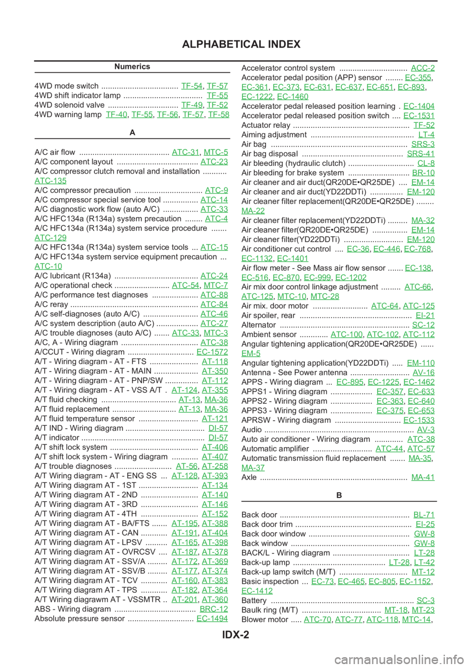
Air cleaner filter replacement(QR20DE•QR25DE) ........
MA-22
Air cleaner filter replacement(YD22DDTi) ......... MA-32
Air cleaner filter(QR20DE•QR25DE) ................ EM-14
Air cleaner filter(YD22DDTi) ........................... EM-120
Air conditioner cut control .... EC-36,EC-446,EC-768,
EC-1132
,EC-1401
Air flow meter - See Mass air flow sensor ....... EC-138,
EC-516
,EC-870,EC-999,EC-1202
Air mix door control linkage adjustment ......... ATC-66,
ATC-125
,MTC-10,MTC-28
Air mix. door motor ......................... ATC-64,ATC-125
Air spoiler, rear ................................................... EI-21
Alternator ........................................................... SC-12
Ambient sensor ............. ATC-100,ATC-102,ATC-112
Angular tightening application(QR20DE•QR25DE) ......
EM-5
Angular tightening application(YD22DDTi) ..... EM-110
Antenna - See Power antenna ........................... AV-16
APPS - Wiring diagram ... EC-895,EC-1225,EC-1462
APPS1 - Wiring diagram ................... EC-357,EC-633
APPS2 - Wiring diagram ................... EC-363,EC-640
APPS3 - Wiring diagram ................... EC-375,EC-653
APRSW - Wiring diagram .............................. EC-1533
Audio .................................................................... AV-3
Auto air conditioner - Wiring diagram ............. ATC-38
Automatic amplifier ........................... ATC-44,ATC-57
Automatic transmission fluid replacement ....... MA-35,
MA-37
Axle ................................................................... MA-41
B
Back door ........................................................... BL-71
Back door trim ..................................................... EI-25
Back door window .............................................. GW-8
Back window ...................................................... GW-8
BACK/L - Wiring diagram ................................... LT-28
Back-up lamp .......................................... LT-28,LT-42
Back-up lamp switch (M/T) ............................... MT-12
Basic inspection ... EC-73,EC-465,EC-805,EC-1152,
EC-1412
Battery ................................................................. SC-3
Baulk ring (M/T) .................................... MT-18,MT-23
Blower motor ..... ATC-70,ATC-77,ATC-118,MTC-14,
Page 3828 of 3833
IDX-4
ALPHABETICAL INDEX
Cylinder head bolt tightening(YD22DDTi) ....... EM-184
Cylinder head gasket selection(YD22DDTi) ... EM-185
Cylinder head(QR20DE•QR25DE) ................... EM-59
Cylinder head(YD22DDTi) .............................. EM-182
D
Data link connector .......... EC-424
,EC-745,EC-1111,
EC-1385
Data link connector for Consult ........... EC-96,EC-488,
EC-827
,EC-1174,EC-1431
Daytime light system ............................................. LT-9
Daytime running light - See Daytime light system LT-9
DEF - Wiring diagram ....................................... GW-15
Desiccant Assembly ....................... ATC-30,ATC-146
Diagnosis sensor unit ..................................... SRS-40
Diagnostic trouble code (DTC) ...................... EC-1406
Diagnostic trouble code (DTC) for OBD system EC-20,
EC-47
,EC-432,EC-454,EC-753,EC-779,EC-1119,
EC-1141
,EC-1393
Diagnostic trouble code (DTC) inspection priority chart
EC-70
,EC-463,EC-802,EC-1150
Differential gear (FF M/T) ..................... MT-21,MT-26
DLC - Wiring diagram ...... EC-424,EC-745,EC-1111,
EC-1385
Door glass ........................................... GW-44,GW-46
Door glass Fitting Adjustment ............. GW-44,GW-46
Door lock ................................................. BL-65,BL-68
Door mirror ........................................................ GW-49
Door trim ............................................................. EI-23
Door, front ............................................................ BL-8
Door, rear ............................................................. BL-8
Drive belt inspection(QR20DE•QR25DE) ......... MA-19
Drive belt inspection(YD22DDTi) ...................... MA-26
Drive belt(QR20DE•QR25DE) .......................... EM-12
Drive belt(YD22DDTi) ..................................... EM-118
Drive shaft (front) ............................................. FAX-11
Drive shaft (rear) ............................................... RAX-9
Driver air bag .................................................. SRS-29
Dropping resistor (A/T) ...................... AT-169,AT-402
DTC work support .............................. EC-103,EC-834
DTRL - Wiring diagram ......................................... LT-9
Dual pressure switch ........ ATC-18,ATC-85,ATC-143
Duct and grilles ............................... ATC-127,MTC-29
E
ECM input/output signal ....... EC-87
,EC-479,EC-819,
EC-1166
ECM power supply EC-116,EC-267,EC-507,EC-580,
EC-848
,EC-995,EC-1193,EC-1269,EC-1442
ECM relay ...................................................... EC-1538
ECM/PW - Wiring diagram . EC-268,EC-581,EC-996,
EC-1270
ECMRLY - Wiring diagram ............................ EC-1539
ECTS - Wiring diagram ...... EC-151,EC-525,EC-883,
EC-1211
,EC-1457
EDU - Wiring diagram .................................... EC-1503
EGR function ................................................. EC-1551
EGR volume control valve ............................. EC-1551
EGRC/V - Wiring diagram .............................. EC-1553
Electric sunroof .................................................... RF-3
Electric throttle control actuator ....... EC-276,EC-278,
EC-584
,EC-586,EC-1010,EC-1012,EC-1273,
EC-1275
Electrical unit .................................................... PG-71
Electrical units location ..................................... PG-63
Electronic drive unit (EDU) ............................ EC-1501
Electronic fuel injection pump(YD22DDTi) ...... EM-147
Electronic ignition (EI) system EC-35,EC-445,EC-768,
EC-1132
Engine control circuit diagram EC-85,EC-477,EC-817,
EC-1164
,EC-1423
Engine control component parts location .......... EC-81,
EC-473
,EC-813,EC-1160
Engine control module (ECM) .......... EC-260,EC-573,
EC-988
,EC-1262,EC-1536
Engine control system diagram and chart ........ EC-31,
EC-441
,EC-763,EC-1127,EC-1398
Engine coolant temperature sensor (ECTS) ... EC-149,
EC-523
,EC-881,EC-1209,EC-1456
Engine coolant(QR20DE•QR25DE) .................... CO-9
Engine coolant(YD22DDTi) .............................. CO-29
Engine fail-safe system ........ EC-71,EC-464,EC-803,
EC-1151
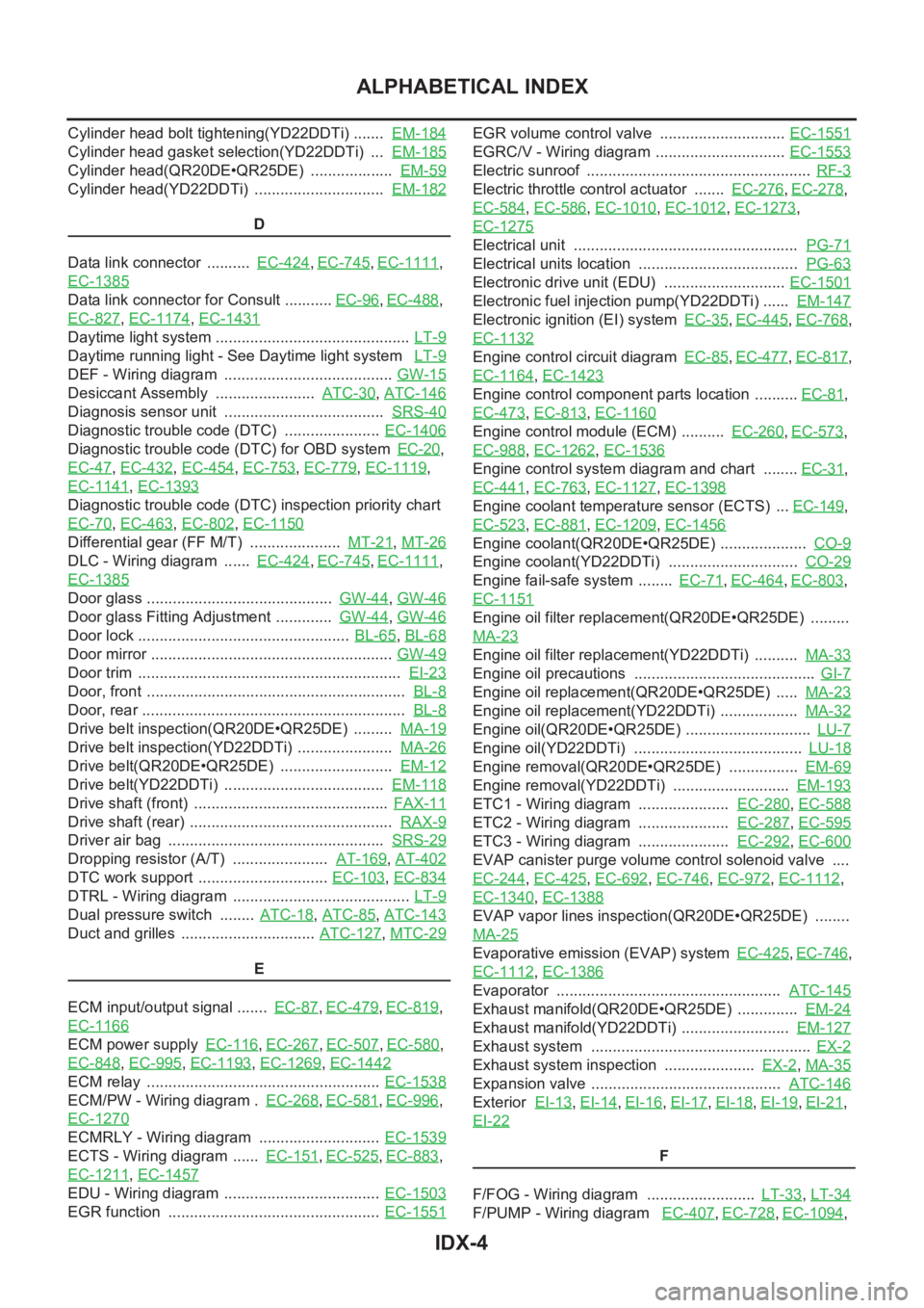
Engine oil filter replacement(QR20DE•QR25DE) .........
MA-23
Engine oil filter replacement(YD22DDTi) .......... MA-33
Engine oil precautions .......................................... GI-7
Engine oil replacement(QR20DE•QR25DE) ..... MA-23
Engine oil replacement(YD22DDTi) .................. MA-32
Engine oil(QR20DE•QR25DE) ............................. LU-7
Engine oil(YD22DDTi) ....................................... LU-18
Engine removal(QR20DE•QR25DE) ................ EM-69
Engine removal(YD22DDTi) ........................... EM-193
ETC1 - Wiring diagram ..................... EC-280,EC-588
ETC2 - Wiring diagram ..................... EC-287,EC-595
ETC3 - Wiring diagram ..................... EC-292,EC-600
EVAP canister purge volume control solenoid valve ....
EC-244
,EC-425,EC-692,EC-746,EC-972,EC-1112,
EC-1340
,EC-1388
EVAP vapor lines inspection(QR20DE•QR25DE) ........
MA-25
Evaporative emission (EVAP) system EC-425,EC-746,
EC-1112
,EC-1386
Evaporator .................................................... ATC-145
Exhaust manifold(QR20DE•QR25DE) .............. EM-24
Exhaust manifold(YD22DDTi) ......................... EM-127
Exhaust system ................................................... EX-2
Exhaust system inspection ..................... EX-2,MA-35
Expansion valve ............................................ ATC-146
Exterior EI-13,EI-14,EI-16,EI-17,EI-18,EI-19,EI-21,
EI-22
F
F/FOG - Wiring diagram ......................... LT-33
,LT-34
F/PUMP - Wiring diagram EC-407,EC-728,EC-1094,