Page 2978 of 3833
RAX-12
REAR DRIVE SHAFT
Steel Ball
●Check that there is no damage or unusual wear.
Inner Case
●Check that there is no damage or other irregular conditions of ball rolling surface.
●Check that there is no damage to serrated part.
ASSEMBLY
Final Drive Side
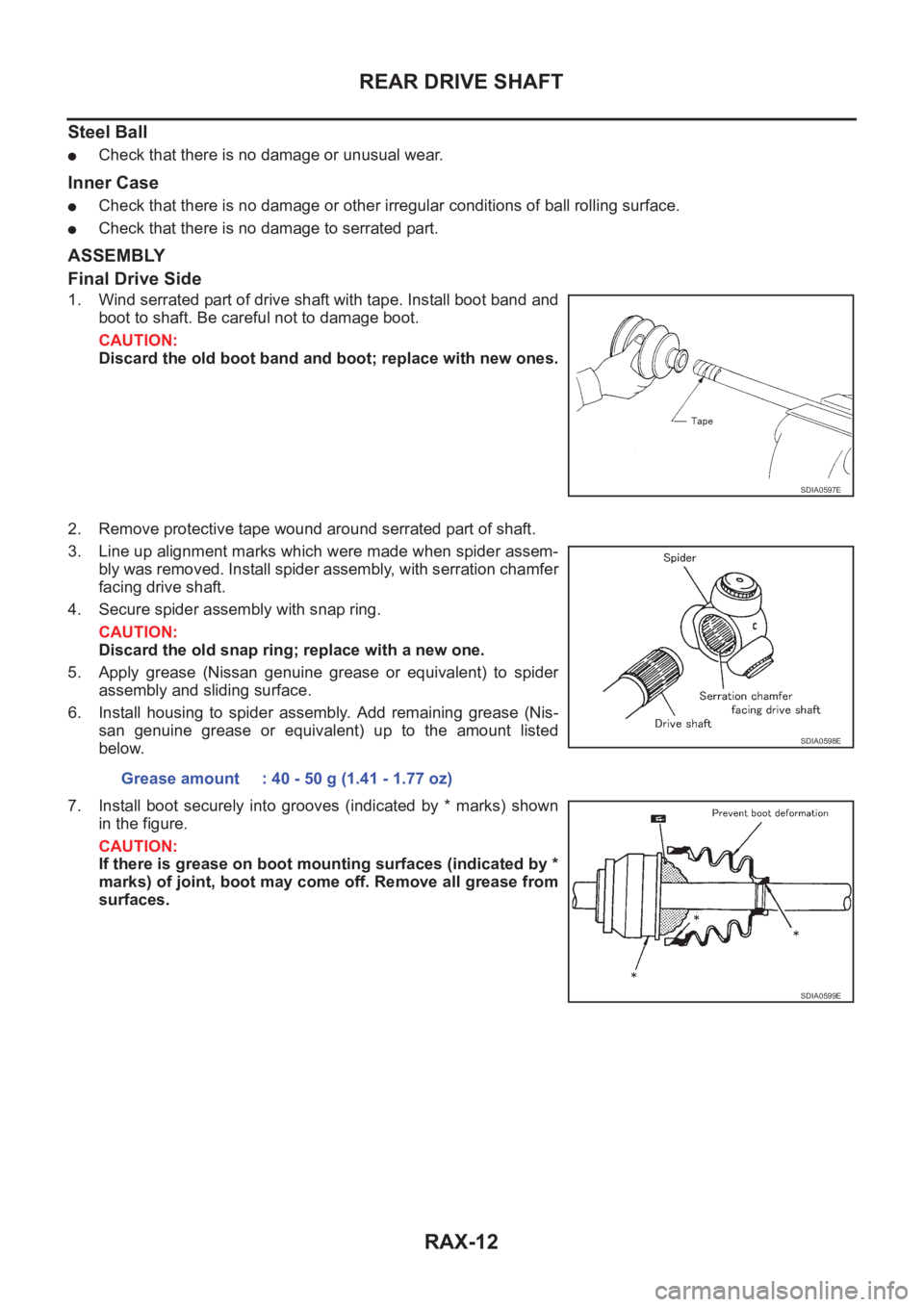
1. Wind serrated part of drive shaft with tape. Install boot band and
boot to shaft. Be careful not to damage boot.
CAUTION:
Discard the old boot band and boot; replace with new ones.
2. Remove protective tape wound around serrated part of shaft.
3. Line up alignment marks which were made when spider assem-
bly was removed. Install spider assembly, with serration chamfer
facing drive shaft.
4. Secure spider assembly with snap ring.
CAUTION:
Discard the old snap ring; replace with a new one.
5. Apply grease (Nissan genuine grease or equivalent) to spider
assembly and sliding surface.
6. Install housing to spider assembly. Add remaining grease (Nis-
san genuine grease or equivalent) up to the amount listed
below.
7. Install boot securely into grooves (indicated by * marks) shown
in the figure.
CAUTION:
If there is grease on boot mounting surfaces (indicated by *
marks) of joint, boot may come off. Remove all grease from
surfaces.
SDIA0597E
Grease amount : 40 - 50 g (1.41 - 1.77 oz)
SDIA0598E
SDIA0599E
Page 2979 of 3833
REAR DRIVE SHAFT
RAX-13
C
E
F
G
H
I
J
K
L
MA
B
RAX
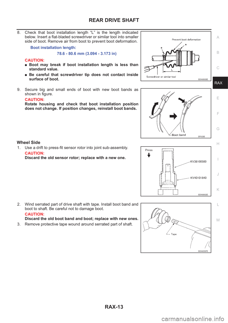
8. Check that boot installation length “L” is the length indicated
below. Insert a flat-bladed screwdriver or similar tool into smaller
side of boot. Remove air from boot to prevent boot deformation.
CAUTION:
●Boot may break if boot installation length is less than
standard value.
●Be careful that screwdriver tip does not contact inside
surface of boot.
9. Secure big and small ends of boot with new boot bands as
shown in figure.
CAUTION:
Rotate housing and check that boot installation position
does not change. If position changes, reinstall boot bands.
Wheel Side
1. Use a drift to press-fit sensor rotor into joint sub-assembly.
CAUTION:
Discard the old sensor rotor; replace with a new one.
2. Wind serrated part of drive shaft with tape. Install boot band and
boot to shaft. Be careful not to damage boot.
CAUTION:
Discard the old boot band and boot; replace with new ones.
3. Remove protective tape wound around serrated part of shaft.Boot installation length:
78.6 - 80.6 mm (3.094 - 3.173 in)
SDIA0600E
SFA395
SDIA0602E
SDIA0597E
Page 2980 of 3833
RAX-14
REAR DRIVE SHAFT
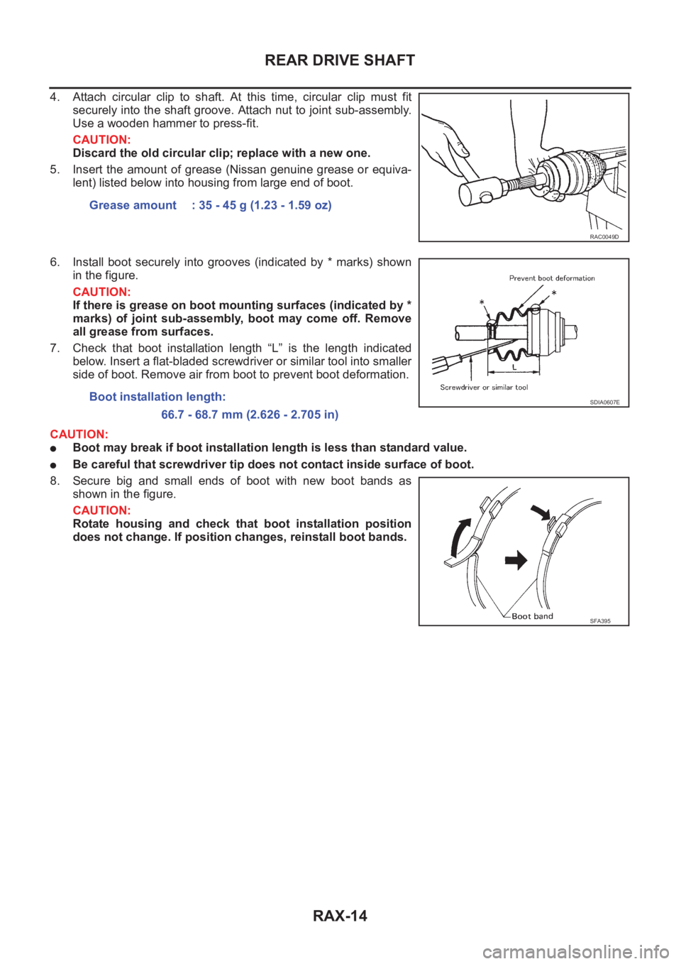
4. Attach circular clip to shaft. At this time, circular clip must fit
securely into the shaft groove. Attach nut to joint sub-assembly.
Use a wooden hammer to press-fit.
CAUTION:
Discard the old circular clip; replace with a new one.
5. Insert the amount of grease (Nissan genuine grease or equiva-
lent) listed below into housing from large end of boot.
6. Install boot securely into grooves (indicated by * marks) shown
in the figure.
CAUTION:
If there is grease on boot mounting surfaces (indicated by *
marks) of joint sub-assembly, boot may come off. Remove
all grease from surfaces.
7. Check that boot installation length “L” is the length indicated
below. Insert a flat-bladed screwdriver or similar tool into smaller
side of boot. Remove air from boot to prevent boot deformation.
CAUTION:
●Boot may break if boot installation length is less than standard value.
●Be careful that screwdriver tip does not contact inside surface of boot.
8. Secure big and small ends of boot with new boot bands as
shown in the figure.
CAUTION:
Rotate housing and check that boot installation position
does not change. If position changes, reinstall boot bands.Grease amount : 35 - 45 g (1.23 - 1.59 oz)
RAC0049D
Boot installation length:
66.7 - 68.7 mm (2.626 - 2.705 in)SDIA0607E
SFA395
Page 2981 of 3833
SERVICE DATA AND SPECIFICATIONS (SDS)
RAX-15
C
E
F
G
H
I
J
K
L
MA
B
RAX
SERVICE DATA AND SPECIFICATIONS (SDS)PFP:00030
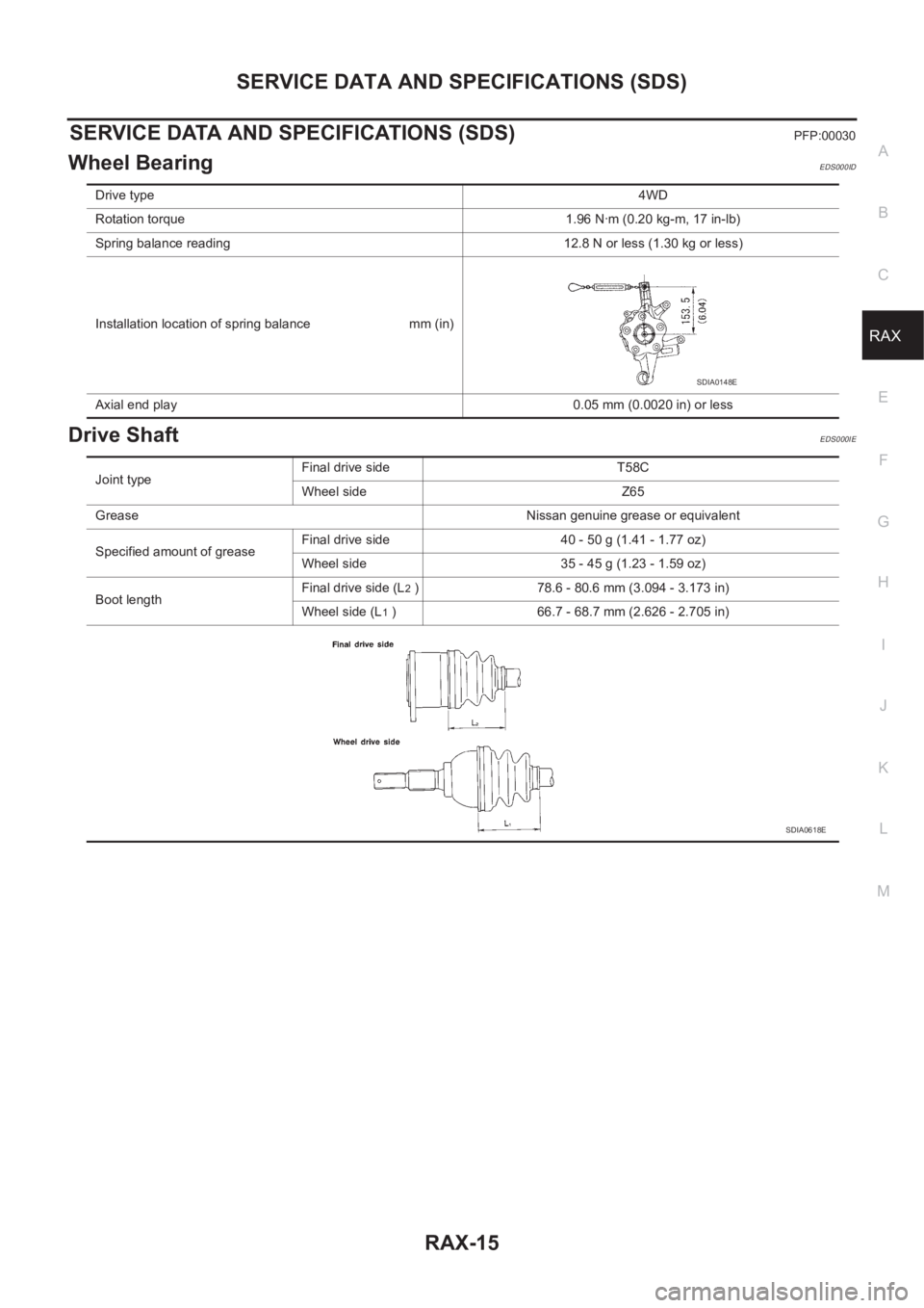
Wheel BearingEDS000ID
Drive ShaftEDS000IE
Drive type4WD
Rotation torque 1.96 N·m (0.20 kg-m, 17 in-lb)
Spring balance reading 12.8 N or less (1.30 kg or less)
Installation location of spring balance mm (in)
Axial end play 0.05 mm (0.0020 in) or less
SDIA0148E
Joint typeFinal drive side T58C
Wheel side Z65
Grease Nissan genuine grease or equivalent
Specified amount of greaseFinal drive side 40 - 50 g (1.41 - 1.77 oz)
Wheel side 35 - 45 g (1.23 - 1.59 oz)
Boot lengthFinal drive side (L
2 ) 78.6 - 80.6 mm (3.094 - 3.173 in)
Wheel side (L
1 ) 66.7 - 68.7 mm (2.626 - 2.705 in)
SDIA0618E
Page 3820 of 3833
MA-40
CHASSIS AND BODY MAINTENANCE
CALIPER
●Check for leakage.
PA D
●Check for wear or damage.
Checking Steering Gear and LinkageELS000BO
STEERING GEAR
●Check gear housing and boots for looseness, damage and
grease leakage.
●Check connection with steering column for looseness.
STEERING LINKAGE
Check ball joint, dust cover and other component parts for looseness, wear, damage and grease leakage.
Checking Power Steering Fluid and LinesELS000BP
Check fluid level in reservoir tank with engine off.
Use “HOT” range at fluid temperatures of 50 to 80°C (122 to 176°F)
or “COLD” range at fluid temperatures of 0 to 30°C (32 to 86°F).
CAUTION:
●Do not overfill.
●Recommended fluid is DEXRONTM III or equivalent.
Refer to MA-16, "
RECOMMENDED FLUIDS AND LUBRI-
CANTS"
SMA922A
Brake model AD31VD AD9VA
Standard thickness 11.0 mm (0.433 in) 8.5 mm (0.335 in)
Minimum thickness
(Wear Limit)2.0 mm (0.079 in) 2.0 mm (0.079 in)
BRA0010D
SLIA0014E
SST850C
Page 3821 of 3833
CHASSIS AND BODY MAINTENANCE
MA-41
C
D
E
F
G
H
I
J
K
MA
B
MA
●Check lines for improper attachment, leaks, cracks, dam-
age, loose connections, chafing and deterioration.
●Check rack boots for accumulation of power steering fluid.
Axle and Suspension PartsELS000BQ
Check front and rear axle and suspension parts for excessive play,
cracks, wear or other damage.
●Shake each wheel to check for excessive play.
●Check wheel bearings for smooth operation.
●Check axle and suspension nuts and bolts for looseness.
●Check strut (shock absorber) for oil leakage or other damage.
●Check suspension ball joint for grease leakage and ball joint
dust cover for cracks or other damage.
Drive ShaftELS000CL
●Check boot and drive shaft for cracks, wear, damage and
grease leakage.
Lubricating Locks, Hinges and Hood LatchesELS000BR
SST851C
SMA525A
SFA392B
SFA108A
Front door Refer to BL-8, "DOOR" .
Back door Refer to BL-71, "
BACK DOOR" .