2001 NISSAN X-TRAIL boot
[x] Cancel search: bootPage 2769 of 3833
REAR DISC BRAKE
BR-29
C
D
E
G
H
I
J
K
L
MA
B
BR
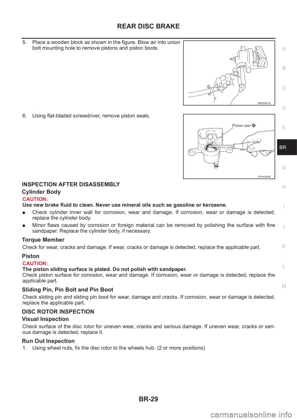
5. Place a wooden block as shown in the figure. Blow air into union
bolt mounting hole to remove pistons and piston boots.
6. Using flat-bladed screwdriver, remove piston seals.
INSPECTION AFTER DISASSEMBLY
Cylinder Body
CAUTION:
Use new brake fluid to clean. Never use mineral oils such as gasoline or kerosene.
●Check cylinder inner wall for corrosion, wear and damage. If corrosion, wear or damage is detected,
replace the cylinder body.
●Minor flaws caused by corrosion or foreign material can be removed by polishing the surface with fine
sandpaper. Replace the cylinder body, if necessary.
Torque Member
Check for wear, cracks and damage. If wear, cracks or damage is detected, replace the applicable part.
Piston
CAUTION:
The piston sliding surface is plated. Do not polish with sandpaper.
Check piston surface for corrosion, wear and damage. If corrosion, wear or damage is detected, replace the
applicable part.
Sliding Pin, Pin Bolt and Pin Boot
Check sliding pin and sliding pin boot for wear, damage and cracks. If corrosion, wear or damage is detected,
replace the applicable part.
DISC ROTOR INSPECTION
Visual Inspection
Check surface of the disc rotor for uneven wear, cracks and serious damage. If uneven wear, cracks or seri-
ous damage is detected, replace it.
Run Out Inspection
1. Using wheel nuts, fix the disc rotor to the wheels hub. (2 or more positions)
BRD0041D
SFIA0340E
Page 2770 of 3833
BR-30
REAR DISC BRAKE
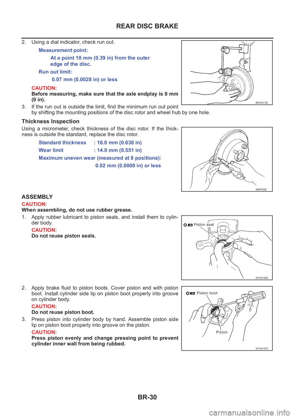
2. Using a dial indicator, check run out.
CAUTION:
Before measuring, make sure that the axle endplay is 0 mm
(0 in).
3. If the run out is outside the limit, find the minimum run out point
by shifting the mounting positions of the disc rotor and wheel hub by one hole.
Thickness Inspection
Using a micrometer, check thickness of the disc rotor. If the thick-
ness is outside the standard, replace the disc rotor.
ASSEMBLY
CAUTION:
When assembling, do not use rubber grease.
1. Apply rubber lubricant to piston seals, and install them to cylin-
der body.
CAUTION:
Do not reuse piston seals.
2. Apply brake fluid to piston boots. Cover piston end with piston
boot. Install cylinder side lip on piston boot properly into groove
on cylinder body.
CAUTION:
Do not reuse piston boot.
3. Press piston into cylinder body by hand. Assemble piston side
lip on piston boot properly into groove on the piston.
CAUTION:
Press piston evenly and change pressing point to prevent
cylinder inner wall from being rubbed.Measurement point:
At a point 10 mm (0.39 in) from the outer
edge of the disc.
Run out limit:
0.07 mm (0.0028 in) or less
BRA0013D
Standard thickness : 16.0 mm (0.630 in)
Wear limit : 14.0 mm (0.551 in)
Maximum uneven wear (measured at 8 positions):
0.02 mm (0.0008 in) or less
SBR020B
SFIA0156E
SFIA0157E
Page 2771 of 3833
REAR DISC BRAKE
BR-31
C
D
E
G
H
I
J
K
L
MA
B
BR
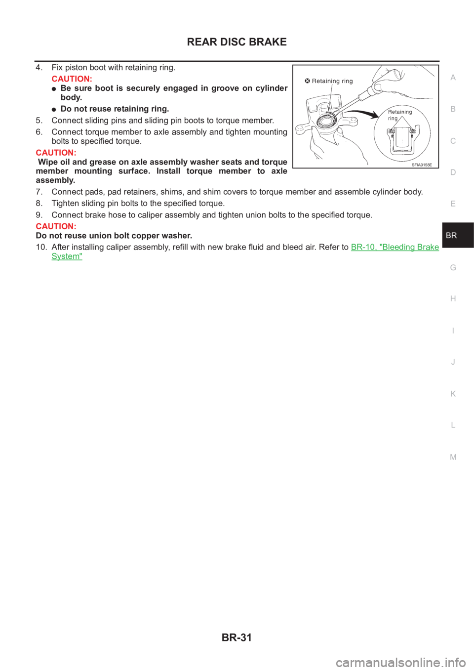
4. Fix piston boot with retaining ring.
CAUTION:
●Be sure boot is securely engaged in groove on cylinder
body.
●Do not reuse retaining ring.
5. Connect sliding pins and sliding pin boots to torque member.
6. Connect torque member to axle assembly and tighten mounting
bolts to specified torque.
CAUTION:
Wipe oil and grease on axle assembly washer seats and torque
member mounting surface. Install torque member to axle
assembly.
7. Connect pads, pad retainers, shims, and shim covers to torque member and assemble cylinder body.
8. Tighten sliding pin bolts to the specified torque.
9. Connect brake hose to caliper assembly and tighten union bolts to the specified torque.
CAUTION:
Do not reuse union bolt copper washer.
10. After installing caliper assembly, refill with new brake fluid and bleed air. Refer to BR-10, "
Bleeding Brake
System"
SFIA0158E
Page 2922 of 3833

PS-12
POWER STEERING GEAR AND LINKAGE
POWER STEERING GEAR AND LINKAGE
PFP:49001
Removal and InstallationEGS0004I
REMOVAL
1. Remove cotter pin, and loosen mounting nut. Remove tie rod from steering knuckle with a pitman arm
puller.
CAUTION:
●Be careful not to damage dust boot at ball joint of tie rod.
●Before using pitman arm puller (multi-purpose tool), loosely tighten nut for temporary holding.
2. Mark lower joint and steering gear with paint for easy installation. Remove pinch bolt from gear side of
lower joint.
3. Remove high pressure-side tube and low pressure-side hose of hydraulic piping from steering gear.
4. Remove mounting nuts on upper portion of stabilizer connecting rod and stabilizer clamp mounting bolts.
Move stabilizer toward vehicle front.
5. Remove steering gear assembly mounting bolts and nuts. Remove power steering tube bracket and
steering gear assembly from suspension member.
6. Tilt steering gear to prevent any contact with other parts. Then remove it from right side of vehicle.
INSTALLATION
Paying attention to following items, install in the reverse order of removal.
●After installation, bleed air. Refer to PS-5, "Bleeding Hydraulic System" .
●Remove mounting bolt and nut from upper portion of lower joint. This will facilitate installation of lower joint
to steering gear. Then slide lower joint in place.
● Check lower slit of lower joint is engaged with projection on rear
cover cap. Install pinch bolt for lower portion of lower joint.
Check steering gear is in straight-ahead position. Also check
rear cover is in position shown in figure. Then install lower joint
to steering gear.
1. Power steering gear assembly 2. Power steering tube bracket 3. Cotter pin
SGIA0009E
SGIA0105E
Page 2925 of 3833
POWER STEERING GEAR AND LINKAGE
PS-15
C
D
E
F
H
I
J
K
L
MA
B
PS
Disassembly and AssemblyEGS0004K
DISASSEMBLY
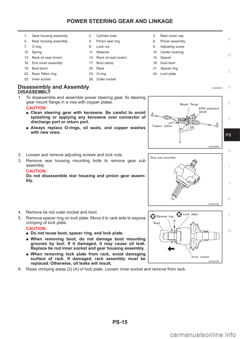
1. To disassemble and assemble power steering gear, fix steering
gear mount flange in a vise with copper plates.
CAUTION:
●Clean steering gear with kerosene. Be careful to avoid
splashing or applying any kerosene over connector of
discharge port or return port.
●Always replace O-rings, oil seals, and copper washes
with new ones.
2. Loosen and remove adjusting screws and lock nuts.
3. Remove rear housing mounting bolts to remove gear sub
assembly.
CAUTION:
Do not disassemble rear housing and pinion gear assem-
bly.
4. Remove tie rod outer socket and boot.
5. Remove spacer ring on lock plate. Move it to rack side to expose
crimping of lock plate.
CAUTION:
●Do not reuse boot, spacer ring, and lock plate.
●When removing boot, do not damage boot mounting
grooves by tool. If it damaged, it may cause oil leak.
Replace tie rod inner socket and gear housing assembly.
●When removing lock plate from rack, avoid damaging
surface of rack. If damaged, rack assembly must be
replaced. Otherwise, oil leaks will result.
6. Raise crimping areas (2) (A) of lock plate. Loosen inner socket and remove from rack.
1. Gear housing assembly 2. Cylinder tube 3. Rear cover cap
4. Rear housing assembly 5. Pinion seal ring 6. Pinion assembly
7. O ring 8. Lock nut 9. Adjusting screw
10. Spring 11. Retainer 12. Center bushing
13. Rack oil seal (inner) 14. Rack oil seal (outer) 15. Spacer
16. End cover assembly 17. Boot clamp 18. Dust boot
19. Boot band 20. Rack 21. Spacer ring
22. Rack Teflon ring 23. O-ring 24. Lock plate
25. Inner socket 26. Outer socket
SGIA0056E
SGIA0018E
SGIA0019E
Page 2926 of 3833

PS-16
POWER STEERING GEAR AND LINKAGE
7. Drill out punch crimping area on cylinder outer rim with a 3 mm
(0.12 in) drill bit [Drill for approx. 1.5 mm (0.059 in) in depth.]
8. Remove end cover with a 36 mm (1.42 in) open head.
CAUTION:
When removing, avoid damaging surface of rack. If dam-
aged, rack assembly must be replaced. Otherwise, oil leaks
will result.
9. Pull rack assembly with rack Teflon ring out of gear housing
assembly.
CAUTION:
When pulling out rack assembly, do not damage cylinder
inner wall. If it damaged, it may cause oil leak. Replace gear
housing assembly.
10. Heat Teflon ring to approx. 40°C (104°F) with a hot air blower Remove it and O-ring from rack. Be careful
not to damage rack.
11. Use a taped 29 mm (1.14 in) socket and an extension bar. Push
out and remove center bushing and rack oil seal together from
gear housing assembly.
CAUTION:
●Be careful not to damage gear housing assembly and cyl-
inder inner wall.
●If damaged, gear housing assembly must be replaced.
Otherwise, oil leaks will result.
INSPECTION AFTER DISASSEMBLY
Boot
Check boot for tear, wrinkle, and deformation. Replace it, if necessary.
Rack
Check rack gear for damage and wear. Replace it, if necessary.
Gear subassembly
●Check pinion gear for damage and wear, and replace if necessary.
●Check bearing while rotating it. Replace bearing if bearing ball race was dent, worn, or damaged.
Gear housing cylinder
Check gear housing cylinder for damage and scratch (inner wall). Replace it, if necessary.
Tie rod ball joint
1. Swing torque.
STC0013D
SGIA0461E
SGIA0467E
Page 2932 of 3833

PS-22
POWER STEERING GEAR AND LINKAGE
25. Position boot band on large-diameter side before installing it.
26. Install small-diameter side of boot to inner socket boot mounting
groove.
27. Install boot band to small-diameter side of boot.
28. Install boot clamp.
a. Tighten large-diameter side of RH/LH boot with boot clamp
(stainless wire).
b. Wrap clamp around boot groove for two turns. Insert screwdriv-
ers in loops on both ends of wire. Twist 4 to 4.5 turns while pull-
ing them with force of approx. 98 N (10 kg, 22.1 lb).
c. Twist boot clamp as shown. Pay attention to relationship
between winding and twisting directions.
d. Twisted point should face front of vehicle with gear installed on
vehicle (to prevent interference with other parts).
e. After twisting wire 4 to 4.5 turns, bend cut end of wire. Cut end of
wire should not touch boot. Be sure wire end is at least 5 mm
(0.20 in) away from clearance for tube.
SGIA0374E
Wire length ( ): 370 mm (14.57 in)
SST097B
SST440A
SGIA0025E
STC0124D
Page 2960 of 3833
FAX-12
FRONT DRIVE SHAFT
●When the drive shafts listed below have been removed, check that a circular clip is attached to the end.
×: Applicable
–: Not applicable
●Remove installation bolt from right-side drive shaft support bearing bracket. Then remove bracket from
engine.
●Remove installation bolt from right-side drive shaft and remove drive shaft from side shaft.
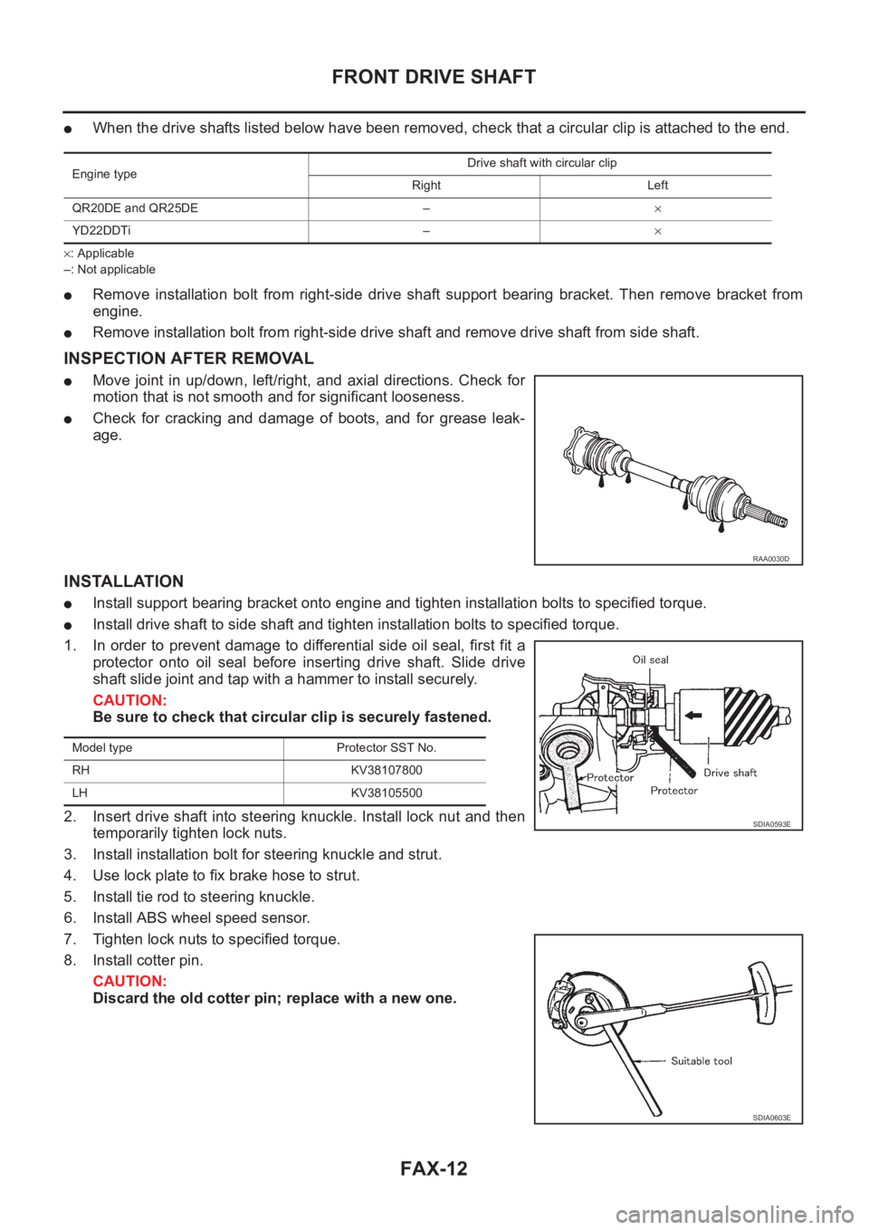
INSPECTION AFTER REMOVAL
●Move joint in up/down, left/right, and axial directions. Check for
motion that is not smooth and for significant looseness.
●Check for cracking and damage of boots, and for grease leak-
age.
INSTALLATION
●Install support bearing bracket onto engine and tighten installation bolts to specified torque.
●Install drive shaft to side shaft and tighten installation bolts to specified torque.
1. In order to prevent damage to differential side oil seal, first fit a
protector onto oil seal before inserting drive shaft. Slide drive
shaft slide joint and tap with a hammer to install securely.
CAUTION:
Be sure to check that circular clip is securely fastened.
2. Insert drive shaft into steering knuckle. Install lock nut and then
temporarily tighten lock nuts.
3. Install installation bolt for steering knuckle and strut.
4. Use lock plate to fix brake hose to strut.
5. Install tie rod to steering knuckle.
6. Install ABS wheel speed sensor.
7. Tighten lock nuts to specified torque.
8. Install cotter pin.
CAUTION:
Discard the old cotter pin; replace with a new one.
Engine typeDrive shaft with circular clip
Right Left
QR20DE and QR25DE –×
YD22DDTi –×
RAA0030D
Model type Protector SST No.
RH KV38107800
LH KV38105500
SDIA0593E
SDIA0603E