2001 NISSAN X-TRAIL em-147
[x] Cancel search: em-147Page 197 of 3833
![NISSAN X-TRAIL 2001 Service Repair Manual FUEL SUPPLY PUMP
EM-147
[YD22DDTi]
C
D
E
F
G
H
I
J
K
L
MA
EM
FUEL SUPPLY PUMPPFP:00018
Removal and InstallationEBS00LRP
CAUTION:
●Before removing and installing fuel supply pump, be sure to](/manual-img/5/57405/w960_57405-196.png "NISSAN X-TRAIL 2001 Service Repair Manual FUEL SUPPLY PUMP
EM-147
[YD22DDTi]
C
D
E
F
G
H
I
J
K
L
MA
EM
FUEL SUPPLY PUMPPFP:00018
Removal and InstallationEBS00LRP
CAUTION:
●Before removing and installing fuel supply pump, be sure to")
FUEL SUPPLY PUMP
EM-147
[YD22DDTi]
C
D
E
F
G
H
I
J
K
L
MA
EM
FUEL SUPPLY PUMPPFP:00018
Removal and InstallationEBS00LRP
CAUTION:
●Before removing and installing fuel supply pump, be sure to remove sprocket. Do not loosen or
remove installation nut in the center of fuel supply pump. If loosened or removed, replace fuel
supply pump.
●After removing timing chain, do not turn crankshaft and camshaft separately, or valves will strike
piston heads.
●When installing camshafts, chain tensioners, oil seals, or other sliding parts, lubricate contacting
surfaces with new engine oil.
●Apply new engine oil to parts marked in illustration before installation.
REMOVAL
1. Remove engine coolant reservoir tank.
2. Remove charge air cooler. Refer to EM-122, "
Removal and Installation" .
3. Remove RH engine mount insulator and bracket. Refer to EM-193, "
Removal and Installation" .
4. Pull power steering reservoir tank out of brackets to move power steering piping.
CAUTION:
To avoid removing power steering reservoir tank out of brackets move it with power steering pip-
ing aside.
1. Washer 2. Fuel supply pump sprocket 3. Fuel supply pump
4. Fuel supply pump rear bracket 5. Fuel connector (Feed side) 6. Fuel connector (Return side)
7. Fuel supply pump housing 8. Coupling 9. Sprocket
SBIA0436E
Page 217 of 3833
![NISSAN X-TRAIL 2001 Service Repair Manual SECONDARY TIMING CHAIN
EM-167
[YD22DDTi]
C
D
E
F
G
H
I
J
K
L
MA
EM
SECONDARY TIMING CHAINPFP:13028
Removal and InstallationEBS00LRT
CAUTION:
●After removing timing chain, do not turn crankshaft and](/manual-img/5/57405/w960_57405-216.png "NISSAN X-TRAIL 2001 Service Repair Manual SECONDARY TIMING CHAIN
EM-167
[YD22DDTi]
C
D
E
F
G
H
I
J
K
L
MA
EM
SECONDARY TIMING CHAINPFP:13028
Removal and InstallationEBS00LRT
CAUTION:
●After removing timing chain, do not turn crankshaft and")
SECONDARY TIMING CHAIN
EM-167
[YD22DDTi]
C
D
E
F
G
H
I
J
K
L
MA
EM
SECONDARY TIMING CHAINPFP:13028
Removal and InstallationEBS00LRT
CAUTION:
●After removing timing chain, do not turn crankshaft and camshaft separately, or valves will strike
piston heads.
●When installing camshafts, chain tensioners, oil seals or other sliding parts, lubricate contacting
surfaces with new engine oil.
●Apply new engine oil to parts marked in illustration before installation.
REMOVAL
●For preparative work for removing/installing secondary timing chain to remove/install electronic fuel supply
pump. Refer to EM-147, "
FUEL SUPPLY PUMP" .
●To prepare for removing/installing secondary timing chain to remove/install camshaft. Refer to EM-158,
"Removal and Installation" .
1. Remove engine coolant reservoir tank.
2. Remove RH engine mount insulator and bracket. Refer to EM-193, "
Removal and Installation" .
3. Pull power steering reservoir tank out of brackets to move power steering piping.
CAUTION:
To avoid removing power steering reservoir tank out of brackets move it with power steering pip-
ing aside.
PBIC1238E
Page 249 of 3833
![NISSAN X-TRAIL 2001 Service Repair Manual CYLINDER BLOCK
EM-199
[YD22DDTi]
C
D
E
F
G
H
I
J
K
L
MA
EM
e. Hoist engine and install it to the engine stand.
NOTE:
It is possible to set engine sub-attachment and engine attach-
ment to eng](/manual-img/5/57405/w960_57405-248.png "NISSAN X-TRAIL 2001 Service Repair Manual CYLINDER BLOCK
EM-199
[YD22DDTi]
C
D
E
F
G
H
I
J
K
L
MA
EM
e. Hoist engine and install it to the engine stand.
NOTE:
It is possible to set engine sub-attachment and engine attach-
ment to eng")
CYLINDER BLOCK
EM-199
[YD22DDTi]
C
D
E
F
G
H
I
J
K
L
MA
EM
e. Hoist engine and install it to the engine stand.
NOTE:
It is possible to set engine sub-attachment and engine attach-
ment to engine stand at first, then install engine later.
●Commercial engine stand can be used.
NOTE:
The figure shows an example of general-purpose engine
stand that can hold mating surface of transmission with drive
plate and rear plate removed.
5. Drain engine oil and engine coolant from inside engine.
6. Remove the following parts and related parts. (Only major parts are listed.)
●Intake manifold (Refer to EM-123, "Removal and Installation" .)
●Exhaust manifold and Turbocharger (Refer to EM-127, "Removal and Installation" .)
●Rocker cover (Refer to EM-156, "Removal and Installation" .)
●Injection tube and fuel injector (Refer to EM-144, "Removal and Installation" .)
●Oil pan and oil strainer (Refer to EM-133, "Removal and Installation" .)
●Water pump (Refer to CO-39, "WATER PUMP" .)
●Thermostat and water piping (Refer to CO-41, "THERMOSTAT AND WATER PIPING" .)
●Vacuum pump and vacuum pipe (Refer to EM-139, "Removal and Installation" .)
●Secondary timing chain (Refer to EM-167, "Removal and Installation" .)
●Primary timing chain (Refer to EM-172, "Removal and Installation" .)
●Fuel supply pump (Refer to EM-147, "Removal and Installation" .)
●Camshaft (Refer to EM-158, "Removal and Installation" .)
●Cylinder head (Refer to EM-183, "Removal and Installation" .)
●Oil cooler (Refer to LU-25, "OIL COOLER" .)
●Accessory, accessory bracket and mount brackets
7. Remove fuel supply pump bracket.
8. Remove rear oil seal retainer.
JEM193G
PBIC0085E
Page 1848 of 3833
![NISSAN X-TRAIL 2001 Service Repair Manual EC-1498
[YD]
DTC P1180 FUEL TEMPERATURE SENSOR
Diagnostic Procedure
EBS004T8
1. CHECK FUEL TEMPERATURE SENSOR POWER SUPPLY CIRCUIT
1. Turn ignition switch “OFF”.
2. Disconnect fuel temperature se](/manual-img/5/57405/w960_57405-1847.png "NISSAN X-TRAIL 2001 Service Repair Manual EC-1498
[YD]
DTC P1180 FUEL TEMPERATURE SENSOR
Diagnostic Procedure
EBS004T8
1. CHECK FUEL TEMPERATURE SENSOR POWER SUPPLY CIRCUIT
1. Turn ignition switch “OFF”.
2. Disconnect fuel temperature se")
EC-1498
[YD]
DTC P1180 FUEL TEMPERATURE SENSOR
Diagnostic Procedure
EBS004T8
1. CHECK FUEL TEMPERATURE SENSOR POWER SUPPLY CIRCUIT
1. Turn ignition switch “OFF”.
2. Disconnect fuel temperature sensor harness connector.
3. Turn ignition switch “ON”.
4. Check voltage between fuel temperature sensor terminal 1 and
engine ground.
OK or NG
OK >> GO TO 2.
NG >> Repair harness or connectors.
2. CHECK FUEL TEMPERATURE SENSOR GROUND CIRCUIT FOR OPEN AND SHORT
1. Turn ignition switch “OFF”.
2. Check harness continuity between fuel temperature sensor terminal 2 and ground. Refer to Wiring Dia-
gram.
3. Also check harness for short to ground and short to power.
OK or NG
OK >> GO TO 4.
NG >> GO TO 3.
3. DETECT MALFUNCTIONING PART
Check harness for open or short to between ECM and fuel temperature sensor.
>> Repair open circuit or short to ground or short to power in harness or connectors.
4. CHECK INTERMITTENT INCIDENT
Refer to EC-1441, "
TROUBLE DIAGNOSIS FOR INTERMITTENT INCIDENT" .
>>INSPECTION END
Removal and InstallationEBS008Z2
FUEL SUPPLY PUMP
Refer to EM-147, "FUEL SUPPLY PUMP" .
PBIB0464E
Voltage: Approximately 5V
PBIB0420E
Continuity should exist.
Page 1874 of 3833
![NISSAN X-TRAIL 2001 Service Repair Manual EC-1524
[YD]
DTC P1233 - P1234 SUCTION CONTROL VALVE
Removal and Installation
EBS008Z7
FUEL SUPPLY PUMP
Refer to EM-147, "FUEL SUPPLY PUMP" .](/manual-img/5/57405/w960_57405-1873.png "NISSAN X-TRAIL 2001 Service Repair Manual EC-1524
[YD]
DTC P1233 - P1234 SUCTION CONTROL VALVE
Removal and Installation
EBS008Z7
FUEL SUPPLY PUMP
Refer to EM-147, \"FUEL SUPPLY PUMP\" .")
EC-1524
[YD]
DTC P1233 - P1234 SUCTION CONTROL VALVE
Removal and Installation
EBS008Z7
FUEL SUPPLY PUMP
Refer to EM-147, "FUEL SUPPLY PUMP" .
Page 1880 of 3833
![NISSAN X-TRAIL 2001 Service Repair Manual EC-1530
[YD]
DTC P1305 FUEL LEAK
FUEL SUPPLY PUMP
Refer to EM-147, "FUEL SUPPLY PUMP" .](/manual-img/5/57405/w960_57405-1879.png "NISSAN X-TRAIL 2001 Service Repair Manual EC-1530
[YD]
DTC P1305 FUEL LEAK
FUEL SUPPLY PUMP
Refer to EM-147, \"FUEL SUPPLY PUMP\" .")
EC-1530
[YD]
DTC P1305 FUEL LEAK
FUEL SUPPLY PUMP
Refer to EM-147, "FUEL SUPPLY PUMP" .
Page 3828 of 3833
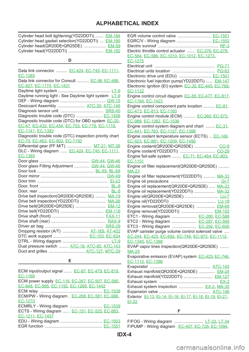
IDX-4
ALPHABETICAL INDEX
Cylinder head bolt tightening(YD22DDTi) ....... EM-184
Cylinder head gasket selection(YD22DDTi) ... EM-185
Cylinder head(QR20DE•QR25DE) ................... EM-59
Cylinder head(YD22DDTi) .............................. EM-182
D
Data link connector .......... EC-424
,EC-745,EC-1111,
EC-1385
Data link connector for Consult ........... EC-96,EC-488,
EC-827
,EC-1174,EC-1431
Daytime light system ............................................. LT-9
Daytime running light - See Daytime light system LT-9
DEF - Wiring diagram ....................................... GW-15
Desiccant Assembly ....................... ATC-30,ATC-146
Diagnosis sensor unit ..................................... SRS-40
Diagnostic trouble code (DTC) ...................... EC-1406
Diagnostic trouble code (DTC) for OBD system EC-20,
EC-47
,EC-432,EC-454,EC-753,EC-779,EC-1119,
EC-1141
,EC-1393
Diagnostic trouble code (DTC) inspection priority chart
EC-70
,EC-463,EC-802,EC-1150
Differential gear (FF M/T) ..................... MT-21,MT-26
DLC - Wiring diagram ...... EC-424,EC-745,EC-1111,
EC-1385
Door glass ........................................... GW-44,GW-46
Door glass Fitting Adjustment ............. GW-44,GW-46
Door lock ................................................. BL-65,BL-68
Door mirror ........................................................ GW-49
Door trim ............................................................. EI-23
Door, front ............................................................ BL-8
Door, rear ............................................................. BL-8
Drive belt inspection(QR20DE•QR25DE) ......... MA-19
Drive belt inspection(YD22DDTi) ...................... MA-26
Drive belt(QR20DE•QR25DE) .......................... EM-12
Drive belt(YD22DDTi) ..................................... EM-118
Drive shaft (front) ............................................. FAX-11
Drive shaft (rear) ............................................... RAX-9
Driver air bag .................................................. SRS-29
Dropping resistor (A/T) ...................... AT-169,AT-402
DTC work support .............................. EC-103,EC-834
DTRL - Wiring diagram ......................................... LT-9
Dual pressure switch ........ ATC-18,ATC-85,ATC-143
Duct and grilles ............................... ATC-127,MTC-29
E
ECM input/output signal ....... EC-87
,EC-479,EC-819,
EC-1166
ECM power supply EC-116,EC-267,EC-507,EC-580,
EC-848
,EC-995,EC-1193,EC-1269,EC-1442
ECM relay ...................................................... EC-1538
ECM/PW - Wiring diagram . EC-268,EC-581,EC-996,
EC-1270
ECMRLY - Wiring diagram ............................ EC-1539
ECTS - Wiring diagram ...... EC-151,EC-525,EC-883,
EC-1211
,EC-1457
EDU - Wiring diagram .................................... EC-1503
EGR function ................................................. EC-1551
EGR volume control valve ............................. EC-1551
EGRC/V - Wiring diagram .............................. EC-1553
Electric sunroof .................................................... RF-3
Electric throttle control actuator ....... EC-276,EC-278,
EC-584
,EC-586,EC-1010,EC-1012,EC-1273,
EC-1275
Electrical unit .................................................... PG-71
Electrical units location ..................................... PG-63
Electronic drive unit (EDU) ............................ EC-1501
Electronic fuel injection pump(YD22DDTi) ...... EM-147
Electronic ignition (EI) system EC-35,EC-445,EC-768,
EC-1132
Engine control circuit diagram EC-85,EC-477,EC-817,
EC-1164
,EC-1423
Engine control component parts location .......... EC-81,
EC-473
,EC-813,EC-1160
Engine control module (ECM) .......... EC-260,EC-573,
EC-988
,EC-1262,EC-1536
Engine control system diagram and chart ........ EC-31,
EC-441
,EC-763,EC-1127,EC-1398
Engine coolant temperature sensor (ECTS) ... EC-149,
EC-523
,EC-881,EC-1209,EC-1456
Engine coolant(QR20DE•QR25DE) .................... CO-9
Engine coolant(YD22DDTi) .............................. CO-29
Engine fail-safe system ........ EC-71,EC-464,EC-803,
EC-1151
Engine oil filter replacement(QR20DE•QR25DE) .........
MA-23
Engine oil filter replacement(YD22DDTi) .......... MA-33
Engine oil precautions .......................................... GI-7
Engine oil replacement(QR20DE•QR25DE) ..... MA-23
Engine oil replacement(YD22DDTi) .................. MA-32
Engine oil(QR20DE•QR25DE) ............................. LU-7
Engine oil(YD22DDTi) ....................................... LU-18
Engine removal(QR20DE•QR25DE) ................ EM-69
Engine removal(YD22DDTi) ........................... EM-193
ETC1 - Wiring diagram ..................... EC-280,EC-588
ETC2 - Wiring diagram ..................... EC-287,EC-595
ETC3 - Wiring diagram ..................... EC-292,EC-600
EVAP canister purge volume control solenoid valve ....
EC-244
,EC-425,EC-692,EC-746,EC-972,EC-1112,
EC-1340
,EC-1388
EVAP vapor lines inspection(QR20DE•QR25DE) ........
MA-25
Evaporative emission (EVAP) system EC-425,EC-746,
EC-1112
,EC-1386
Evaporator .................................................... ATC-145
Exhaust manifold(QR20DE•QR25DE) .............. EM-24
Exhaust manifold(YD22DDTi) ......................... EM-127
Exhaust system ................................................... EX-2
Exhaust system inspection ..................... EX-2,MA-35
Expansion valve ............................................ ATC-146
Exterior EI-13,EI-14,EI-16,EI-17,EI-18,EI-19,EI-21,
EI-22
F
F/FOG - Wiring diagram ......................... LT-33
,LT-34
F/PUMP - Wiring diagram EC-407,EC-728,EC-1094,