2001 NISSAN X-TRAIL brakes
[x] Cancel search: brakesPage 2602 of 3833
![NISSAN X-TRAIL 2001 Service Repair Manual AT-524
[ALL]
SERVICE DATA AND SPECIFICATIONS (SDS)
RETURN SPRING
Unit: mm (in)
*: Always check with the Parts Department for the latest parts information.
Clutch and BrakesECS004MO
REVERSE CLUTCH
*: A NISSAN X-TRAIL 2001 Service Repair Manual AT-524
[ALL]
SERVICE DATA AND SPECIFICATIONS (SDS)
RETURN SPRING
Unit: mm (in)
*: Always check with the Parts Department for the latest parts information.
Clutch and BrakesECS004MO
REVERSE CLUTCH
*: A](/manual-img/5/57405/w960_57405-2601.png)
AT-524
[ALL]
SERVICE DATA AND SPECIFICATIONS (SDS)
RETURN SPRING
Unit: mm (in)
*: Always check with the Parts Department for the latest parts information.
Clutch and BrakesECS004MO
REVERSE CLUTCH
*: Always check with the Parts Department for the latest parts information.
HIGH CLUTCH
*: Always check with the Parts Department for the latest parts information.
FORWARD CLUTCH
Accumulator Part number* Free length Outer diameter
Servo release accumulator 31605-80X00 52.5 (2.067) 20.1 (0.791)
N-D accumulator 31605-31X15 43.5 (1.713) 28.0 (1.102)
Model code number85X23, 85X64
Number of drive plates2
Number of driven plates2
Drive plate thickness mm (in)Standard 1.6 (0.063)
Allowable limit 1.4 (0.055)
Driven plate thickness mm (in) Standard 1.8 (0.071)
Clearance mm (in)Standard 0.5 - 0.8 (0.020 - 0.031)
Allowable limit 1.2 (0.047)
Thickness of retaining platesThickness mm (in) Part number*
6.6 (0.260)
6.8 (0.268)
7.0 (0.276)
7.2 (0.283)
7.4 (0.291)
7.6 (0.299)
7.8 (0.307)31537-80X05
31537-80X06
31537-80X07
31537-80X08
31537-80X09
31537-80X20
31537-80X21
Model code number85X23, 85X64
Number of drive plates3
Number of driven plates
7*
1 + 1*2
Drive plate
thickness mm (in)Standard 1.6 (0.063)
Allowable limit 1.4 (0.055)
Driven plate
thickness mm (in)*1 Standard 1.4 (0.055)
*2 Standard 2.0 (0.079)
Clearance mm (in)Standard 1.8 - 2.2 (0.071 - 0.087)
Allowable limit 2.8 (0.110)
Thickness of retaining platesThickness mm (in) Part number*
3.2 (0.126)
3.4 (0.134)
3.6 (0.142)
3.8 (0.150)
4.0 (0.157)31537-81X11
31537-81X12
31537-81X13
31537-81X14
31537-81X15
Model code number85X23
Number of drive plates4
Number of driven plates4
Drive plate thickness mm (in)Standard 1.6 (0.063)
Allowable limit 1.4 (0.055)
Page 2710 of 3833
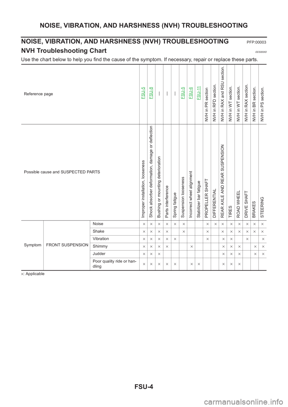
FSU-4
NOISE, VIBRATION, AND HARSHNESS (NVH) TROUBLESHOOTING
NOISE, VIBRATION, AND HARSHNESS (NVH) TROUBLESHOOTING
PFP:00003
NVH Troubleshooting ChartEES000ID
Use the chart below to help you find the cause of the symptom. If necessary, repair or replace these parts.
×: ApplicableReference page
FSU-5FSU-8—
—
—
FSU-5FSU-6FSU-11
NVH in PR section
NVH in RFD section.
NVH in RAX and RSU section.
NVH in WT section.
NVH in WT section.
NVH in RAX section.
NVH in BR section.
NVH in PS section.
Possible cause and SUSPECTED PARTS
Improper installation, looseness
Shock absorber deformation, damage or deflection
Bushing or mounting deterioration
Parts interference
Spring fatigue
Suspension looseness
Incorrect wheel alignment
Stabilizer bar fatigue
PROPELLER SHAFT
DIFFERENTIAL
REAR AXLE AND REAR SUSPENSION
TIRES
ROAD WHEEL
DRIVE SHAFT
BRAKES
STEERING
Symptom FRONT SUSPENSIONNoise××××× × ××× ×××××
Shake×××× × × × ×××××
Vibration××××× × ×× × ×
Shimmy×××× × ××× ××
Judder××× ××× ××
Poor quality ride or han-
dling×× × × × ×× × × ×
Page 2724 of 3833
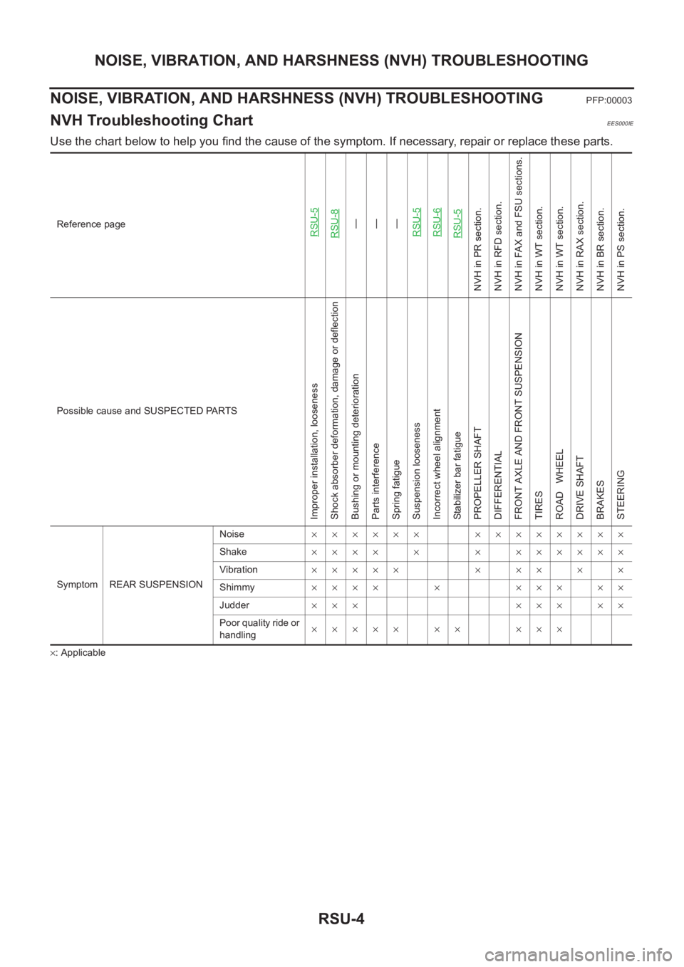
RSU-4
NOISE, VIBRATION, AND HARSHNESS (NVH) TROUBLESHOOTING
NOISE, VIBRATION, AND HARSHNESS (NVH) TROUBLESHOOTING
PFP:00003
NVH Troubleshooting ChartEES000IE
Use the chart below to help you find the cause of the symptom. If necessary, repair or replace these parts.
×: ApplicableReference page
RSU-5RSU-8—
—
—
RSU-5RSU-6RSU-5
NVH in PR section.
NVH in RFD section.
NVH in FAX and FSU sections.
NVH in WT section.
NVH in WT section.
NVH in RAX section.
NVH in BR section.
NVH in PS section.
Possible cause and SUSPECTED PARTS
Improper installation, looseness
Shock absorber deformation, damage or deflection
Bushing or mounting deterioration
Parts interference
Spring fatigue
Suspension looseness
Incorrect wheel alignment
Stabilizer bar fatigue
PROPELLER SHAFT
DIFFERENTIAL
FRONT AXLE AND FRONT SUSPENSION
TIRES
ROAD WHEEL
DRIVE SHAFT
BRAKES
STEERING
Symptom REAR SUSPENSIONNoise×××××× ××××××××
Shake×××× × × ××××××
Vibration××××× × ×× × ×
Shimmy×××× × ××× ××
Judder ××× ××× ××
Poor quality ride or
handling××××× ×× ×××
Page 2741 of 3833
BR-1
BRAKE SYSTEM
F BRAKES
CONTENTS
C
D
E
G
H
I
J
K
L
M
SECTION
A
B
BR
BRAKE SYSTEM
PRECAUTIONS .......................................................... 3
Precautions for Supplemental Restraint System
(SRS) “AIR BAG” and “SEAT BELT PRE-TEN-
SIONER” .................................................................. 3
Precautions for Brake System .................................. 3
PREPARATION ........................................................... 4
Special Service Tools ............................................... 4
Commercial Service Tools ........................................ 4
NOISE, VIBRATION, AND HARSHNESS (NVH)
TROUBLESHOOTING ................................................ 5
NVH Troubleshooting Chart ..................................... 5
BRAKE PEDAL .......................................................... 6
On-Vehicle Inspection and Adjustment .................... 6
Components ............................................................. 7
Removal and Installation .......................................... 7
REMOVAL ............................................................. 7
INSPECTION AFTER REMOVAL ......................... 7
INSTALLATION ..................................................... 8
BRAKE FLUID ............................................................ 9
Checking Brake Fluid Level ..................................... 9
Checking Brake Line ................................................ 9
Changing Brake Fluid ............................................... 9
Brake Burnishing Procedure .................................. 10
Bleeding Brake System .......................................... 10
BRAKE PIPING AND HOSE .....................................11
Hydraulic Piping ...................................................... 11
Removal and Installation of Front Brake Piping and
Brake Hose ............................................................. 11
REMOVAL ............................................................ 11
INSTALLATION .................................................... 11
Removal and Installation of Rear Brake Piping and
Brake Hose ............................................................ 12
REMOVAL ........................................................... 12
INSTALLATION ................................................... 12
Inspection ............................................................... 12
BRAKE MASTER CYLINDER .................................. 13
Components ........................................................... 13
Removal and Installation ........................................ 13
REMOVAL ........................................................... 13INSTALLATION ................................................... 13
Disassembly and Assembly .................................... 14
DISASSEMBLY ................................................... 14
INSPECTION AFTER REMOVAL ....................... 14
ASSEMBLY ......................................................... 15
BRAKE BOOSTER ................................................... 17
On-Vehicle Inspection and Service ......................... 17
FUNCTION INSPECTION ................................... 17
AIRTIGHTNESS INSPECTION ........................... 17
Removal and Installation ........................................ 17
REMOVAL ........................................................... 17
INSPECTION AFTER REMOVAL ....................... 18
INSTALLATION ................................................... 18
VACUUM LINES ....................................................... 19
Removal and Installation ........................................ 19
Inspection ............................................................... 19
VISUAL INSPECTION ......................................... 19
CHECK VALVE INSPECTION ............................. 20
FRONT DISC BRAKE ............................................... 21
Component ............................................................. 21
Inspection ............................................................... 21
PAD THICKNESS ................................................ 21
Pad Replacement ................................................ ... 22
REMOVAL ........................................................... 22
INSTALLATION ................................................... 22
Caliper Removal and Installation ............................ 22
REMOVAL ........................................................... 22
INSTALLATION ................................................... 23
Caliper Disassembly and Assembly ....................... 23
DISASSEMBLY ................................................... 23
INSPECTION AFTER DISASSEMBLY ................ 23
DISC ROTOR INSPECTION ............................... 24
ASSEMBLY ......................................................... 24
BRAKE BURNISHING PROCEDURE ................. 25
REAR DISC BRAKE ................................................. 26
Component ............................................................. 26
Inspection ............................................................... 26
PAD WEAR INSPECTION ................................... 26
Pad Replacement ................................................ ... 27
REMOVAL ........................................................... 27
Page 2762 of 3833
BR-22
FRONT DISC BRAKE
Pad Replacement
EFS000CI
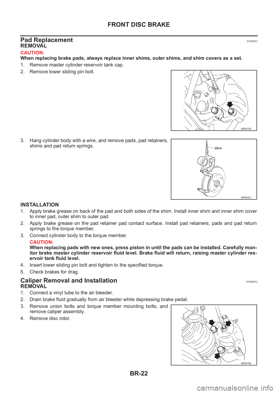
REMOVAL
CAUTION:
When replacing brake pads, always replace inner shims, outer shims, and shim covers as a set.
1. Remove master cylinder reservoir tank cap.
2. Remove lower sliding pin bolt.
3. Hang cylinder body with a wire, and remove pads, pad retainers,
shims and pad return springs.
INSTALLATION
1. Apply brake grease on back of the pad and both sides of the shim. Install inner shim and inner shim cover
to inner pad, outer shim to outer pad.
2. Apply brake grease on the pad retainer pad contact surface. Install pad retainers, pads and pad return
springs to the torque member.
3. Connect cylinder body to the torque member.
CAUTION:
When replacing pads with new ones, press piston in until the pads can be installed. Carefully mon-
itor brake master cylinder reservoir fluid level. Brake fluid will return, raising master cylinder res-
ervoir tank fluid level.
4. Insert lower sliding pin bolt and tighten to the specified torque.
5. Check brakes for drag.
Caliper Removal and InstallationEFS000CJ
REMOVAL
1. Connect a vinyl tube to the air bleeder.
2. Drain brake fluid gradually from air bleeder while depressing brake pedal.
3. Remove union bolts and torque member mounting bolts, and
remove caliper assembly.
4. Remove disc rotor.
SBR433D
SBR932C
SBR979B
Page 2767 of 3833
REAR DISC BRAKE
BR-27
C
D
E
G
H
I
J
K
L
MA
B
BR
Pad ReplacementEFS0017Z
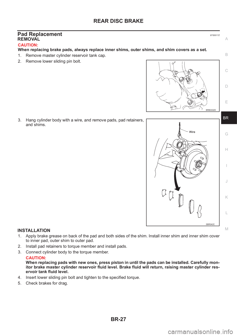
REMOVAL
CAUTION:
When replacing brake pads, always replace inner shims, outer shims, and shim covers as a set.
1. Remove master cylinder reservoir tank cap.
2. Remove lower sliding pin bolt.
3. Hang cylinder body with a wire, and remove pads, pad retainers,
and shims.
INSTALLATION
1. Apply brake grease on back of the pad and both sides of the shim. Install inner shim and inner shim cover
to inner pad, outer shim to outer pad.
2. Install pad retainers to torque member and install pads.
3. Connect cylinder body to the torque member.
CAUTION:
When replacing pads with new ones, press piston in until the pads can be installed. Carefully mon-
itor brake master cylinder reservoir fluid level. Brake fluid will return, raising master cylinder res-
ervoir tank fluid level.
4. Insert lower sliding pin bolt and tighten to the specified torque.
5. Check brakes for drag.
BRB0302D
SBR042C
Page 2775 of 3833
PB-1
PARKING BRAKE SYSTEM
F BRAKES
CONTENTS
C
D
E
G
H
I
J
K
L
M
SECTION
A
B
PB
PARKING BRAKE SYSTEM
NOISE, VIBRATION, AND HARSHNESS (NVH)
TROUBLESHOOTING ................................................ 2
NVH Troubleshooting Chart ..................................... 2
PARKING BRAKE CONTROL ................................... 3
Components ............................................................. 3
Removal and Installation .......................................... 3
Inspection ................................................................. 3
Adjustment ............................................................... 4PARKING BRAKE SHOE ........................................... 5
Components ............................................................. 5
Removal and Installation .......................................... 5
REMOVAL ............................................................. 5
INSPECTION ........................................................ 7
INSTALLATION ..................................................... 7
SERVICE DATA AND SPECIFICATIONS (SDS) ...... 10
Parking Brake ......................................................... 10
Page 2785 of 3833
BRC-1
BRAKE CONTROL SYSTEM
F BRAKES
CONTENTS
C
D
E
G
H
I
J
K
L
M
SECTION
A
B
BRC
BRAKE CONTROL SYSTEM
4WD/ABS
PRECAUTIONS .......................................................... 4
Precautions for brake system ................................... 4
Precautions for brake control ................................... 4
PREPARATION ........................................................... 5
Special Service Tool ................................................. 5
Commercial Service Tool ......................................... 5
ALL MODE 4X4 SYSTEM .......................................... 6
System Description .................................................. 6
ABS FUNCTION ................................................... 6
4WD FUNCTION ................................................... 6
Control System Diagram .......................................... 6
TROUBLE DIAGNOSIS .............................................. 7
Fail-safe Function ..................................................... 7
How to Proceed with Trouble Diagnosis .................. 7
BASIC CONCEPT ................................................. 7
DIAGNOSIS FLOW ............................................... 8
ASKING COMPLAINTS ........................................ 9
TROUBLE DIAGNOSIS SHEET - EXAMPLE ....... 9
Component Parts Location ..................................... 10
Schematic ............................................................... 11
Wiring Diagram — ABS — ..................................... 12
Trouble Diagnosis Chart by Symptom .................... 18
4WD/ABS Control Unit Input/Output Signal Stan-
dard ........................................................................ 19
4WD/ABS CONTROL UNIT CONNECTOR TER-
MINAL ARRANGEMENT .................................... 19
REFERENCE STANDARD TABLE ..................... 19
CONSULT-II Functions ........................................... 23
CONSULT-II FUNCTION APPLICATION TABLE ... 23
SELF-DIAGNOSIS .............................................. 24
DATA MONITOR ................................................. 26
ACTIVE TEST ..................................................... 29
Component Inspection ........................................... 30
ABS ACTUATOR ................................................ 30
4WD SOLENOID VALVE .................................... 32
Basic Inspection ..................................................... 32
BASIC INSPECTION 1 BRAKE FLUID LEVEL
AND LEAKAGE INSPECTION ............................ 32
BASIC INSPECTION 2 INSPECTION FOR LOOSE POWER SUPPLY TERMINAL ............... 32
BASIC INSPECTION 3 ABS/4WD WARNING
LAMP INSPECTION ............................................ 32
Wheel Sensor System ............................................ 32
INSPECTION PROCEDURE .............................. 32
Control Unit Power Supply System ........................ 34
INSPECTION PROCEDURE .............................. 34
G -Sensor System (4WD models) .......................... 34
INSPECTION PROCEDURE .............................. 34
4WD Solenoid, Actuator Relay System .................. 35
4WD Mode Switch System ..................................... 37
Trouble Diagnoses for Symptoms .......................
... 38
4WD INDICATOR LAMP DOES NOT COME ON
FOR APPROXIMATELY 1 SECOND WHEN THE
IGNITION SWITCH IS TURNED TO ON ............. 38
4WD WARNING LAMP DOES NOT ILLUMINATE
WITH IGNITION ON ............................................ 39
4WD WARNING LAMP DOES NOT GO OUT
SEVERAL SECONDS AFTER ENGINE
STARTED.(4WD MODE INDICATOR LAMP
GOES OUT) ........................................................ 39
HEAVY TIGHT-CORNER BRAKING SYMPTOM
OCCURS WHEN THE VEHICLE IS DRIVEN IN
AUTO MODE AND THE STEERING WHEEL IS
TURNED FULLY TO EITHER SIDE AFTER THE
ENGINE IS STARTED ......................................... 39
4WD MODES CANNOT BE SWITCHED AFTER
ENGINE IS STARTED ......................................... 41
WHILE DRIVING, 4WD WARNING LAMP
FLASHES RAPIDLY. (WHEN IT FLASHERS FOR
APPROX. ONE MINUTE, THEN DOES NOT
ILLUMINATE.) ..................................................... 41
WHILE DRIVING, 4WD WARNING LAMP
FLASHES SLOWLY. (WHEN IT CONTINUES TO
ILLUMINATE UNTIL ENGINE TURNS OFF.) ...... 41
VEHICLE DOES NOT ENTER 4WD MODE
EVEN THOUGH 4WD WARNING LAMP IS OFF. ... 41
TIGHT-CORNER BRAKING SYMPTOM
OCCURS WHEN THE VEHICLE IS STARTED IN
AUTO WARNING LAMP REMAIN OFF). ............ 42