Page 2020 of 3833
MT-44
TRANSAXLE ASSEMBLY
CAUTION:
Do not reuse the O-ring.
i. Install shift check and stopper bolt.
CAUTION:
Does not reuse shift check and stopper bolt.
31. Using a drift, install bore plug.
CAUTION:
Do not reuse bore plug.
32. Using a drift, install welch plug.
CAUTION:
Do not reuse welch plug.
33. Install 2 check balls, 2 check springs and 2 check ball plugs.
CAUTION:
Do not reuse check ball plug.
34. Apply recommended sealant to threads of neutral switch and
reverse lamp switch. Then install them into transaxle case.
35. Install gaskets onto drain plug and filler plug, and then install
them into transaxle case.
CAUTION:
●Do not reuse gasket.
●After oil is filled, tighten filler plug to specified torque.
SCIA0894E
SCIA0403E
SCIA1667E
SCIA0895E
Page 2036 of 3833

MT-60
INPUT SHAFT AND GEARS
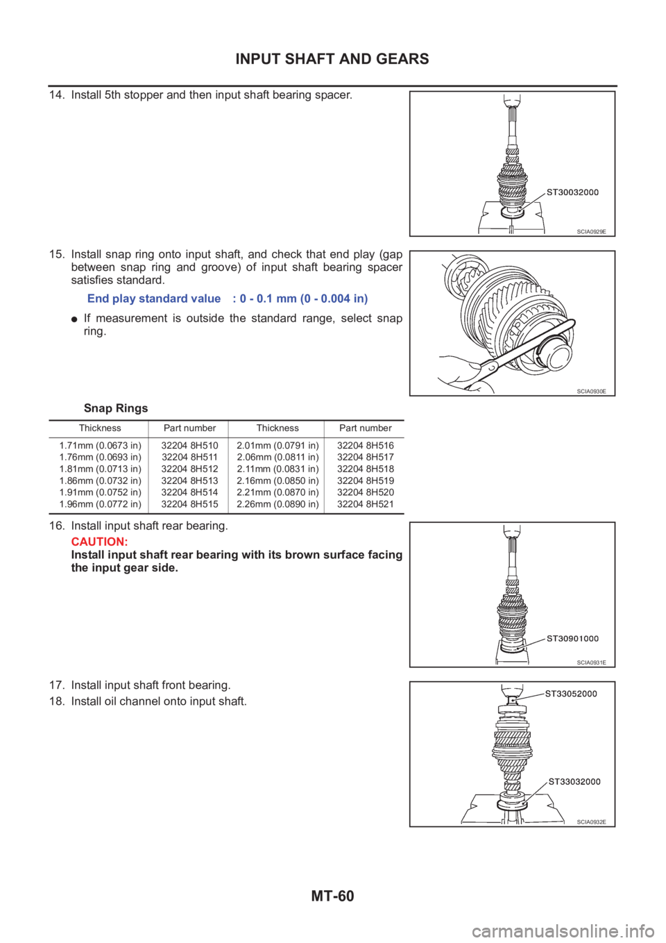
14. Install 5th stopper and then input shaft bearing spacer.
15. Install snap ring onto input shaft, and check that end play (gap
between snap ring and groove) of input shaft bearing spacer
satisfies standard.
●If measurement is outside the standard range, select snap
ring.
Snap Rings
16. Install input shaft rear bearing.
CAUTION:
Install input shaft rear bearing with its brown surface facing
the input gear side.
17. Install input shaft front bearing.
18. Install oil channel onto input shaft.
SCIA0929E
End play standard value : 0 - 0.1 mm (0 - 0.004 in)
SCIA0930E
Thickness Part number Thickness Part number
1.71mm (0.0673 in)
1.76mm (0.0693 in)
1.81mm (0.0713 in)
1.86mm (0.0732 in)
1.91mm (0.0752 in)
1.96mm (0.0772 in)32204 8H510
32204 8H511
32204 8H512
32204 8H513
32204 8H514
32204 8H5152.01mm (0.0791 in)
2.06mm (0.0811 in)
2.11mm (0.0831 in)
2.16mm (0.0850 in)
2.21mm (0.0870 in)
2.26mm (0.0890 in)32204 8H516
32204 8H517
32204 8H518
32204 8H519
32204 8H520
32204 8H521
SCIA0931E
SCIA0932E
Page 2037 of 3833
INPUT SHAFT AND GEARS
MT-61
D
E
F
G
H
I
J
K
L
MA
B
MT
19. Check end play of 3rd, 4th, and 5th input gears.
Assembly and Disassembly (RS6F51A)ECS008C5
DISASSEMBLY
1. Before disassembling, measure end play for 3rd, 4th, 5th and
6th input gears.
2. Remove oil channel.
3. Remove input shaft rear bearing.
4. Remove the snap ring.
5. Remove 6th input gear, 6th bushing and 6th needle bearing.
6. Remove 6th baulk ring, 5th-6th coupling sleeve and shifting
insert.End play standard value
3rd gear : 0.18 - 0.31 mm (0.0071 - 0.0122 in)
4th gear : 0.20 - 0.30 mm (0.0079 - 0.0118 in)
5th gear : 0.06 - 0.16 mm (0.0024 - 0.0063 in)
SCIA0914E
End play standard value
3rd gear : 0.18 - 0.31 mm (0.0071 - 0.0122 in)
4th gear : 0.20 - 0.30 mm (0.0079 - 0.0118 in)
5th gear : 0.06 - 0.16 mm (0.0024 - 0.0063 in)
6th gear : 0.06 - 0.16 mm (0.0024 - 0.0063 in)
SCIA0966E
SCIA0967E
SCIA0968E
Page 2043 of 3833

INPUT SHAFT AND GEARS
MT-67
D
E
F
G
H
I
J
K
L
MA
B
MT
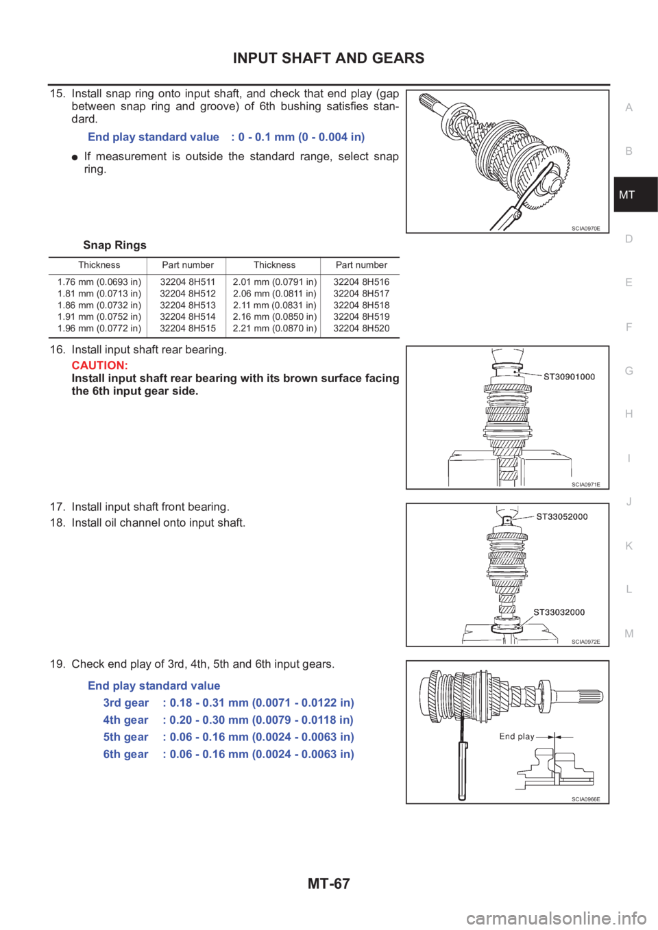
15. Install snap ring onto input shaft, and check that end play (gap
between snap ring and groove) of 6th bushing satisfies stan-
dard.
●If measurement is outside the standard range, select snap
ring.
Snap Rings
16. Install input shaft rear bearing.
CAUTION:
Install input shaft rear bearing with its brown surface facing
the 6th input gear side.
17. Install input shaft front bearing.
18. Install oil channel onto input shaft.
19. Check end play of 3rd, 4th, 5th and 6th input gears.End play standard value : 0 - 0.1 mm (0 - 0.004 in)
SCIA0970E
Thickness Part number Thickness Part number
1.76 mm (0.0693 in)
1.81 mm (0.0713 in)
1.86 mm (0.0732 in)
1.91 mm (0.0752 in)
1.96 mm (0.0772 in)32204 8H511
32204 8H512
32204 8H513
32204 8H514
32204 8H5152.01 mm (0.0791 in)
2.06 mm (0.0811 in)
2.11 mm (0.0831 in)
2.16 mm (0.0850 in)
2.21 mm (0.0870 in)32204 8H516
32204 8H517
32204 8H518
32204 8H519
32204 8H520
SCIA0971E
SCIA0972E
End play standard value
3rd gear : 0.18 - 0.31 mm (0.0071 - 0.0122 in)
4th gear : 0.20 - 0.30 mm (0.0079 - 0.0118 in)
5th gear : 0.06 - 0.16 mm (0.0024 - 0.0063 in)
6th gear : 0.06 - 0.16 mm (0.0024 - 0.0063 in)
SCIA0966E
Page 2063 of 3833

FINAL DRIVE
MT-87
D
E
F
G
H
I
J
K
L
MA
B
MT
FINAL DRIVEPFP:38411
Assembly and Disassembly (RS5F51A)ECS008CA
PRE-INSPECTION
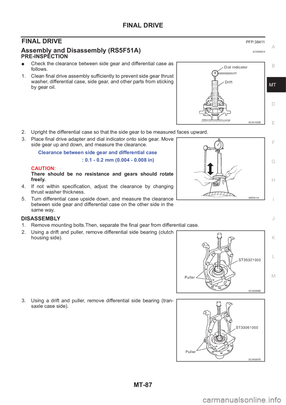
●Check the clearance between side gear and differential case as
follows.
1. Clean final drive assembly sufficiently to prevent side gear thrust
washer, differential case, side gear, and other parts from sticking
by gear oil.
2. Upright the differential case so that the side gear to be measured faces upward.
3. Place final drive adapter and dial indicator onto side gear. Move
side gear up and down, and measure the clearance.
CAUTION:
There should be no resistance and gears should rotate
freely.
4. If not within specification, adjust the clearance by changing
thrust washer thickness.
5. Turn differential case upside down, and measure the clearance
between side gear and differential case on the other side in the
same way.
DISASSEMBLY
1. Remove mounting bolts.Then, separate the final gear from differential case.
2. Using a drift and puller, remove differential side bearing (clutch
housing side).
3. Using a drift and puller, remove differential side bearing (tran-
saxle case side).
SCIA1020E
Clearance between side gear and differential case
: 0.1 - 0.2 mm (0.004 - 0.008 in)
SMT611A
SCIA0906E
SCIA0907E
Page 2064 of 3833
MT-88
FINAL DRIVE
4. Using a pin punch, pull out lock pin and pinion mate shaft.
5. Rotate pinion mate gears, and remove pinion mate gears, pinion
mate thrust washers, side gears, and side gear thrust washers
from differential case.
INSPECTION AFTER DISASSEMBLY
Gear, Washer, Shaft and Case
●Check side gears, side gear thrust washers, pinion mate shaft,
pinion mate gears, pinion mate thrust washers and differential
case. If necessary, replace with a new one.
Bearing
●Check for bearing damage and rough rotation. If necessary,
replace with a new one.
CAUTION:
When replacing tapered roller bearing, replace outer and inner
races as a set.
ASSEMBLY
1. Apply gear oil to sliding area of differential case, each gear, and thrust washer.
2. Install side gear thrust washers and side gears into differential
case.
3. While rotating pinion mate thrust washers and pinion mate
gears, aligning them diagonally, install them into differential
case.
SCIA0908E
MTK0135D
SPD715
SMT839
Page 2066 of 3833
MT-90
FINAL DRIVE
7. Using a drift (special service tool), install differential side bearing
(transaxle case side).
8. Using a drift (special service tool), install differential side bearing
(clutch housing side).
9. Install final gear into differential case, and tighten final gear
mounting bolts.
Assembly and Disassembly (RS6F51A)ECS008CB
PRE-INSPECTION
●Check the clearance between side gear and differential case as
follows.
1. Clean final drive assembly sufficiently to prevent side gear thrust
washer, differential case, side gear, and other parts from sticking
by gear oil.
2. Upright the differential case so that the side gear to be measured faces upward.
SCIA0910E
SCIA0911E
SCIA0912E
SCIA1020E
Page 2068 of 3833
MT-92
FINAL DRIVE
INSPECTION AFTER DISASSEMBLY
Gear, Washer, Shaft and Case
●Check side gears, side gear thrust washers, pinion mate shaft,
pinion mate gears, pinion mate thrust washers and differential
case. If necessary, replace with a new one.
Bearing
●Check for bearing damage and rough rotation. If necessary,
replace with a new one.
CAUTION:
When replacing tapered roller bearing, replace outer and inner
races as a set.
ASSEMBLY
1. Apply gear oil to sliding area of differential case, each gear, and thrust washer.
2. Install side gear thrust washers and side gears into differential
case.
3. While rotating pinion mate thrust washers and pinion mate
gears, aligning them diagonally, install them into differential
case.
4. Insert pinion mate shaft into differential case.
CAUTION:
Be sure not to damage pinion mate thrust washers.
MTK0135D
SPD715
SMT839
MTK0132D