2001 NISSAN X-TRAIL check oil
[x] Cancel search: check oilPage 1752 of 3833
![NISSAN X-TRAIL 2001 Service Repair Manual EC-1402
[YD]
ENGINE CONTROL SYSTEM
Crankcase Ventilation System
EBS0036K
DESCRIPTION
In this system, blow-by gas is sucked into the air duct after oil separation by oil separator in the rocker cover.
NISSAN X-TRAIL 2001 Service Repair Manual EC-1402
[YD]
ENGINE CONTROL SYSTEM
Crankcase Ventilation System
EBS0036K
DESCRIPTION
In this system, blow-by gas is sucked into the air duct after oil separation by oil separator in the rocker cover.](/manual-img/5/57405/w960_57405-1751.png)
EC-1402
[YD]
ENGINE CONTROL SYSTEM
Crankcase Ventilation System
EBS0036K
DESCRIPTION
In this system, blow-by gas is sucked into the air duct after oil separation by oil separator in the rocker cover.
INSPECTION
Ventilation Hose
1. Check hoses and hose connections for leaks.
2. Disconnect all hoses and clean with compressed air. If any hose
cannot be freed of obstructions, replace.
CAN CommunicationEBS00NBH
SYSTEM DESCRIPTION
CAN (Controller Area Network) is a serial communication line for real time application. It is an on-vehicle mul-
tiplex communication line with high data communication speed and excellent error detection ability. Many elec-
tronic control units are equipped onto a vehicle, and each control unit shares information and links with other
control units during operation (not independent). In CAN communication, control units are connected with 2
communication lines (CAN H line, CAN L line) allowing a high rate of information transmission with less wiring.
Each control unit transmits/receives data but selectively reads required data only.
PBIB0590E
SEC692
Page 1859 of 3833
![NISSAN X-TRAIL 2001 Service Repair Manual DTC P1217 OVERHEAT (COOLING SYSTEM)
EC-1509
[YD]
C
D
E
F
G
H
I
J
K
L
MA
EC
When the engine coolant temperature reaches an abnormally high temperature condition, a malfunction is
indicated. NISSAN X-TRAIL 2001 Service Repair Manual DTC P1217 OVERHEAT (COOLING SYSTEM)
EC-1509
[YD]
C
D
E
F
G
H
I
J
K
L
MA
EC
When the engine coolant temperature reaches an abnormally high temperature condition, a malfunction is
indicated.](/manual-img/5/57405/w960_57405-1858.png)
DTC P1217 OVERHEAT (COOLING SYSTEM)
EC-1509
[YD]
C
D
E
F
G
H
I
J
K
L
MA
EC
When the engine coolant temperature reaches an abnormally high temperature condition, a malfunction is
indicated.
CAUTION:
When a malfunction is indicated, be sure to replace the coolant following the procedure in the MA-27,
"Changing Engine Coolant" . Also, replace the engine oil.
1. Fill radiator with coolant up to specified level with a filling speed of 2 liters per minute. Be sure to
use coolant with the proper mixture ratio. Refer to MA-18, "
Engine Coolant Mixture Ratio" .
2. After refilling coolant, run engine to ensure that no water-flow noise is emitted.
Overall Function CheckEBS004QV
Use this procedure to check the overall function of the cooling fan. During this check, a DTC might not be con-
firmed.
WARNING:
Never remove the radiator cap when the engine is hot. Serious burns could be caused by high pres-
sure fluid escaping from the radiator.
Wrap a thick cloth around the cap. Carefully remove the cap by turning it a quarter turn to allow built-
up pressure to escape. Then turn the cap all the way off.
WITH CONSULT-II
1. Check the coolant level in the reservoir tank and radiator.
Allow engine to cool before checking coolant level.
If the coolant level in the reservoir tank and/or radiator is below
the proper range, skip the following steps and go to EC-1511,
"Diagnostic Procedure" .
2. Confirm whether customer filled the coolant or not. If customer
filled the coolant, skip the following steps and go to EC-1511,
"Diagnostic Procedure" .
3. Turn ignition switch “ON”.
4. Perform “COOLING FAN” in “ACTIVE TEST” mode with CON-
SULT-II and make sure that cooling fans operate when touching
“HIGH” or “LOW”.
If NG, go to EC-1511, "
Diagnostic Procedure" .
DTC Malfunction is detected when ... Check Items (Possible Cause)
P1217
●Cooling fan does not operate properly (Overheat).
●Cooling fan system does not operate properly
(Overheat).
●Engine coolant was not added to the system using
the proper filling method.
●Harness or connectors
(The cooling fan circuit is open or shorted.)
●Cooling fan
●Radiator hose
●Radiator
●Radiator cap
●Water pump
●Thermostat
●Engine coolant temperature sensor
For more information, refer to EC-1517, "
Main 12
Causes of Overheating" .
AEC640
SEF111X
Page 1920 of 3833
![NISSAN X-TRAIL 2001 Service Repair Manual EC-1570
[YD]
POWER STEERING OIL PRESSURE SWITCH
Diagnostic Procedure
EBS003PV
1. CHECK OVERALL FUNCTION
With CONSULT-II
1. Start engine.
2. Check “PW/ST SIGNAL” in “DATA MONITOR” mode with CON NISSAN X-TRAIL 2001 Service Repair Manual EC-1570
[YD]
POWER STEERING OIL PRESSURE SWITCH
Diagnostic Procedure
EBS003PV
1. CHECK OVERALL FUNCTION
With CONSULT-II
1. Start engine.
2. Check “PW/ST SIGNAL” in “DATA MONITOR” mode with CON](/manual-img/5/57405/w960_57405-1919.png)
EC-1570
[YD]
POWER STEERING OIL PRESSURE SWITCH
Diagnostic Procedure
EBS003PV
1. CHECK OVERALL FUNCTION
With CONSULT-II
1. Start engine.
2. Check “PW/ST SIGNAL” in “DATA MONITOR” mode with CON-
SULT-II under the following conditions.
OK or NG
OK >>INSPECTION END
NG >> GO TO 2.
2. CHECK POWER STEERING OIL PRESSURE SWITCH GROUND CIRCUIT FOR OPEN AND SHORT
1. Turn ignition switch “OFF”.
2. Disconnect power steering oil pressure switch harness connec-
tor.
3. Check harness continuity between power steering oil pressure
switch terminal 2 and engine ground. Refer to Wiring Diagram.
4. Also check harness for short to power.
OK or NG
OK >> GO TO 3.
NG >> Repair open circuit or short to power in harness or con-
nectors.
3. CHECK POWER STEERING OIL PRESSURE SWITCH INPUT SIGNAL CIRCUIT FOR OPEN AND
SHORT
1. Disconnect ECM harness connector.
2. Check harness continuity between ECM terminal E12 and power steering oil pressure switch terminal 1.
Refer to Wiring Diagram.
3. Also check harness for short to ground and short to power.
OK or NG
OK >> GO TO 4.
NG >> Repair open circuit or short to ground or short to power in harness or connectors.
4. CHECK POWER STEERING OIL PRESSURE SWITCH
Refer to EC-1571, "
Component Inspection" .
OK or NG
OK >> GO TO 5.
NG >> Replace power steering oil pressure switch.
Conditions PW/ST SIGNAL
Steering in neutral position OFF
Steering is turned ON
PBIB0434E
Continuity should exist.
PBIB0375E
Continuity should exist.
Page 1921 of 3833
![NISSAN X-TRAIL 2001 Service Repair Manual POWER STEERING OIL PRESSURE SWITCH
EC-1571
[YD]
C
D
E
F
G
H
I
J
K
L
MA
EC
5.CHECK INTERMITTENT INCIDENT
Refer to EC-1441, "
TROUBLE DIAGNOSIS FOR INTERMITTENT INCIDENT" .
>>INSPECTION END
Comp NISSAN X-TRAIL 2001 Service Repair Manual POWER STEERING OIL PRESSURE SWITCH
EC-1571
[YD]
C
D
E
F
G
H
I
J
K
L
MA
EC
5.CHECK INTERMITTENT INCIDENT
Refer to EC-1441, "
TROUBLE DIAGNOSIS FOR INTERMITTENT INCIDENT" .
>>INSPECTION END
Comp](/manual-img/5/57405/w960_57405-1920.png)
POWER STEERING OIL PRESSURE SWITCH
EC-1571
[YD]
C
D
E
F
G
H
I
J
K
L
MA
EC
5.CHECK INTERMITTENT INCIDENT
Refer to EC-1441, "
TROUBLE DIAGNOSIS FOR INTERMITTENT INCIDENT" .
>>INSPECTION END
Component InspectionEBS003PW
POWER STEERING OIL PRESSURE SWITCH
1. Disconnect power steering oil pressure switch harness connector and then start engine.
2. Check continuity between power steering oil pressure switch ter-
minal 1 and 2 under the following conditions.
Removal and InstallationEBS008ZH
POWER STEERING OIL PRESSURE SWITCH
Refer to PS-34, "HYDRAULIC LINE" .
Conditions Continuity
Steering wheel is being fully turned. Yes
Steering wheel is not being turned. No
PBIB0435E
Page 1932 of 3833
![NISSAN X-TRAIL 2001 Service Repair Manual FL-8
[QR]
FUEL LEVEL SENSOR UNIT, FUEL FILTER AND FUEL PUMP ASSEMBLY
3. Separate the fuel filter and fuel level sensor unit.
a. Fit a used O-ring into space between fuel level sensor unit and
fuel NISSAN X-TRAIL 2001 Service Repair Manual FL-8
[QR]
FUEL LEVEL SENSOR UNIT, FUEL FILTER AND FUEL PUMP ASSEMBLY
3. Separate the fuel filter and fuel level sensor unit.
a. Fit a used O-ring into space between fuel level sensor unit and
fuel](/manual-img/5/57405/w960_57405-1931.png)
FL-8
[QR]
FUEL LEVEL SENSOR UNIT, FUEL FILTER AND FUEL PUMP ASSEMBLY
3. Separate the fuel filter and fuel level sensor unit.
a. Fit a used O-ring into space between fuel level sensor unit and
fuel filter. Undo catches and separate fuel level sensor unit and
fuel filter.
●For reference when reassembling, put a mating mark on outer
edges of fuel level sensor unit and fuel filter with some means
which cannot be erased by fuel.
b. Insert blade end screwdriver to the gap between the fuel filter
and fuel level sensor unit to separate them.
CAUTION:
Put cloth or similar one on the edge of screwdriver not to
damage the inserted portion.
4. Remove pressure regulator from fuel filter.
a. Open and remove the clip.
b. Pull the pressure regulator straight out during removal.
CAUTION:
●Avoid impacts such as falling during removal.
●Do not disassemble or adjust.
ASSEMBLY
Install in the reverse order of removal paying attention to the following.
●Install the fuel filter and fuel pump with the tabs aligned, Make sure a click sound of secure engagement is
heard.
●Securely connect the harness connector of the fuel pump.
●Install the pressure regulator O-ring as follows.
CAUTION:
●When replacing, always use a new O-ring.
●Handle it with bare hands. (Do not use gloves.)
●Visually check the O-ring, mounting parts and mating parts for foreign materials and flaws.
●Before installing, apply new engine oil.
●To avid damage, do not apply an excessive force (pulling or starching).
●Install the pressure regulator as follows.
1. Insert the clip to the groove of the pressure regulator.
2. With the clip installed, insert the pressure regulator straight by
matching the fuel filter protrusion and the clip notch.
3. Make sure that the fuel filter protrusion and clip notch are
securely engaged.
PBIC0244E
PBIC0245E
Page 1977 of 3833

MT-1
MANUAL TRANSAXLE
C TRANSMISSION/TRANSAXLE
CONTENTS
D
E
F
G
H
I
J
K
L
M
SECTION
A
B
MT
MANUAL TRANSAXLE
PRECAUTIONS .......................................................... 3
Caution ..................................................................... 3
PREPARATION ........................................................... 4
Special Service Tools ............................................... 4
Commercial Service Tools ........................................ 6
NOISE, VIBRATION, AND HARSHNESS (NVH)
TROUBLESHOOTING ................................................ 7
NVH Troubleshooting Chart ..................................... 7
MANUAL TRANSAXLE ......................................... 7
DESCRIPTION ............................................................ 8
Cross-Sectional View ............................................... 8
DOUBLE-CONE SYNCHRONIZER ...................... 9
REVERSE GEAR NOISE PREVENTION FUNC-
TION (SYNCHRONIZING METHOD) ................... 9
M/T OIL ..................................................................... 10
Changing M/T Oil ................................................... 10
DRAINING ........................................................... 10
FILLING ............................................................... 10
Checking M/T Oil .................................................... 10
OIL LEAKAGE AND OIL LEVEL ......................... 10
SIDE OIL SEAL .........................................................11
Removal and Installation ......................................... 11
REMOVAL ............................................................ 11
INSTALLATION .................................................... 11
POSITION SWITCH .................................................. 12
Checking ................................................................ 12
BACK-UP LAMP SWITCH .................................. 12
PARK/NEUTRAL POSITION SWITCH ............... 12
CONTROL LINKAGE ............................................... 13
Removal and Installation of Control Device and
Cable ...................................................................... 13
AIR BREATHER HOSE ............................................ 14
Removal and Installation ........................................ 14
TRANSAXLE ASSEMBLY ........................................ 15
Removal and Installation ........................................ 15
REMOVAL ........................................................... 15
INSTALLATION ................................................... 16
Component Parts (RS5F51A) ................................ 17CASE AND HOUSING COMPONENTS .............. 17
GEAR COMPONENTS ....................................... 18
SHIFT CONTROL COMPONENTS ..................... 20
FINAL DRIVE COMPONENTS ........................... 21
Component Parts (RS6F51A) ................................. 22
CASE AND HOUSING COMPONENTS .............. 22
GEAR COMPONENTS ....................................... 23
SHIFT CONTROL COMPONENTS ..................... 25
FINAL DRIVE COMPONENTS ........................... 26
Disassembly and Assembly (RS5F51A) ................. 26
DISASSEMBLY ................................................... 26
ASSEMBLY ......................................................... 30
Disassembly and Assembly (RS6F51A) ................. 35
DISASSEMBLY ................................................... 35
ASSEMBLY ......................................................... 39
Adjustment (RS5F51A) ........................................... 45
INPUT SHAFT END PLAY .................................. 45
MAINSHAFT END PLAY ..................................... 46
DIFFERENTIAL SIDE BEARING PRELOAD ...... 47
REVERSE IDLER GEAR END PLAY .................. 48
Adjustment (RS6F51A) ........................................... 49
INPUT SHAFT END PLAY .................................. 49
MAINSHAFT END PLAY ..................................... 50
DIFFERENTIAL SIDE BEARING PRELOAD ...... 51
REVERSE IDLER GEAR END PLAY .................. 52
INPUT SHAFT AND GEARS .................................... 54
Assembly and Disassembly (RS5F51A) ................. 54
DISASSEMBLY ................................................... 54
INSPECTION AFTER DISASSEMBLY ................ 55
ASSEMBLY ......................................................... 57
Assembly and Disassembly (RS6F51A) ................. 61
DISASSEMBLY ................................................... 61
INSPECTION AFTER DISASSEMBLY ................ 62
ASSEMBLY ......................................................... 64
MAINSHAFT AND GEARS ....................................... 68
Assembly and Disassembly (RS5F51A) ................. 68
DISASSEMBLY ................................................... 68
INSPECTION AFTER DISASSEMBLY ................ 69
Page 1979 of 3833

PRECAUTIONS
MT-3
D
E
F
G
H
I
J
K
L
MA
B
MT
PRECAUTIONSPFP:00001
CautionECS008BM
●Do not reuse transaxle oil, once it has been drained.
●Check oil level or replace oil with vehicle on level ground.
●During removal or installation, keep inside of transaxle clear of dust or dirt.
●Check for the correct installation status prior to removal or disassembly. If mating marks are required, be
certain they do not interfere with the function of the parts they are applied to.
●In principle, tighten bolts or nuts gradually in several steps working diagonally from inside to outside. If
tightening sequence is specified, observe it.
●Be careful not to damage sliding surfaces and mating surfaces.
Page 1983 of 3833

NOISE, VIBRATION, AND HARSHNESS (NVH) TROUBLESHOOTING
MT-7
D
E
F
G
H
I
J
K
L
MA
B
MT
NOISE, VIBRATION, AND HARSHNESS (NVH) TROUBLESHOOTINGPFP:00003
NVH Troubleshooting ChartECS008BP
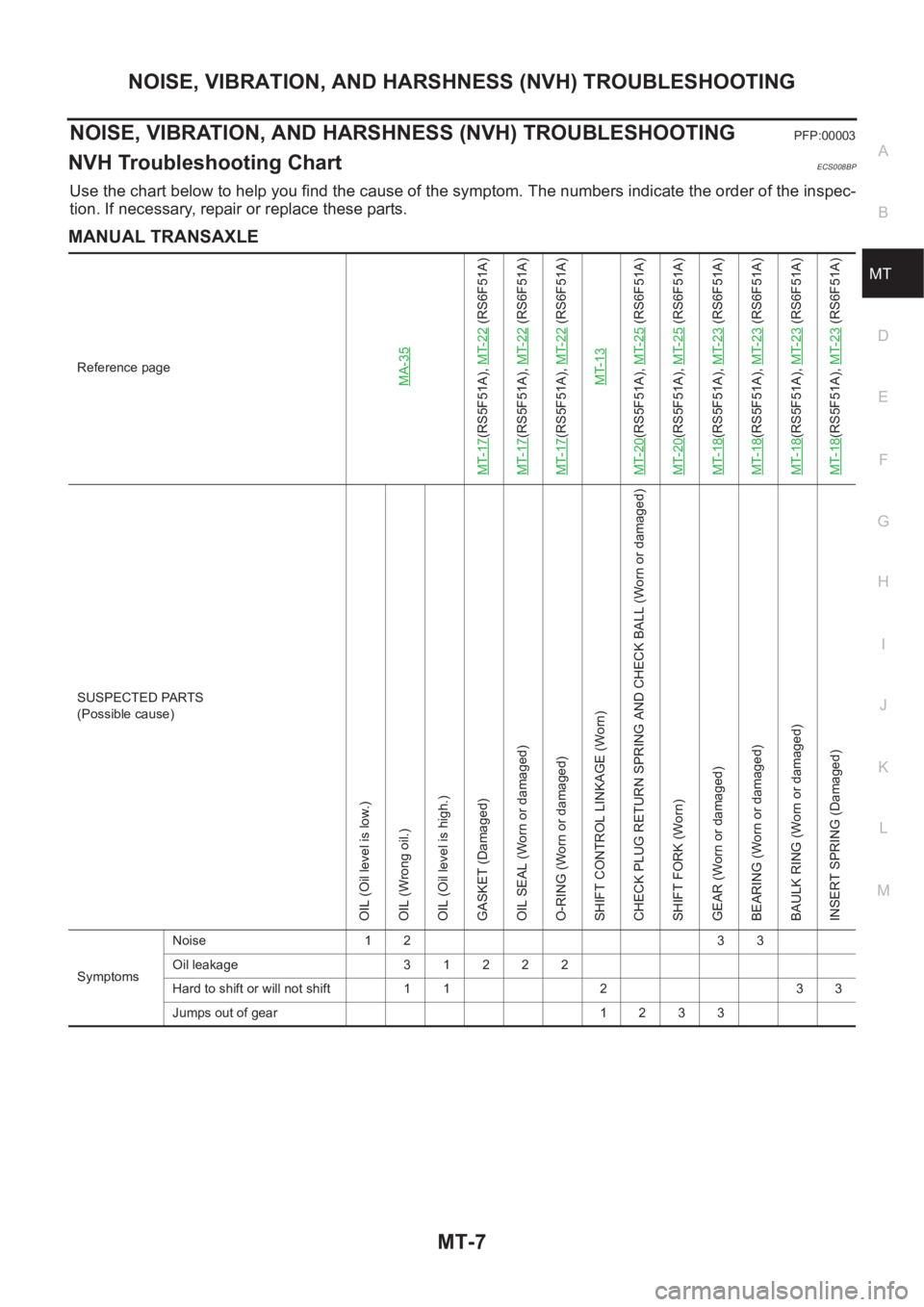
Use the chart below to help you find the cause of the symptom. The numbers indicate the order of the inspec-
tion. If necessary, repair or replace these parts.
MANUAL TRANSAXLE
Reference pageMA-35
MT-17
(RS5F51A), MT-22
(RS6F51A)
MT-17
(RS5F51A), MT-22
(RS6F51A)
MT-17
(RS5F51A), MT-22
(RS6F51A)
MT-13
MT-20
(RS5F51A), MT-25
(RS6F51A)
MT-20
(RS5F51A), MT-25
(RS6F51A)
MT-18
(RS5F51A), MT-23
(RS6F51A)
MT-18
(RS5F51A), MT-23
(RS6F51A)
MT-18
(RS5F51A), MT-23
(RS6F51A)
MT-18
(RS5F51A), MT-23
(RS6F51A)
SUSPECTED PARTS
(Possible cause)
OIL (Oil level is low.)
OIL (Wrong oil.)
OIL (Oil level is high.)
GASKET (Damaged)
OIL SEAL (Worn or damaged)
O-RING (Worn or damaged)
SHIFT CONTROL LINKAGE (Worn)
CHECK PLUG RETURN SPRING AND CHECK BALL (Worn or damaged)
SHIFT FORK (Worn)
GEAR (Worn or damaged)
BEARING (Worn or damaged)
BAULK RING (Worn or damaged)
INSERT SPRING (Damaged)
SymptomsNoise 1 2 3 3
Oil leakage 3 1 2 2 2
Hard to shift or will not shift 1 1 2 3 3
Jumps out of gear 1 2 3 3