2001 NISSAN X-TRAIL steering wheel
[x] Cancel search: steering wheelPage 2971 of 3833
NOISE, VIBRATION, AND HARSHNESS (NVH) TROUBLESHOOTING
RAX-5
C
E
F
G
H
I
J
K
L
MA
B
RAX
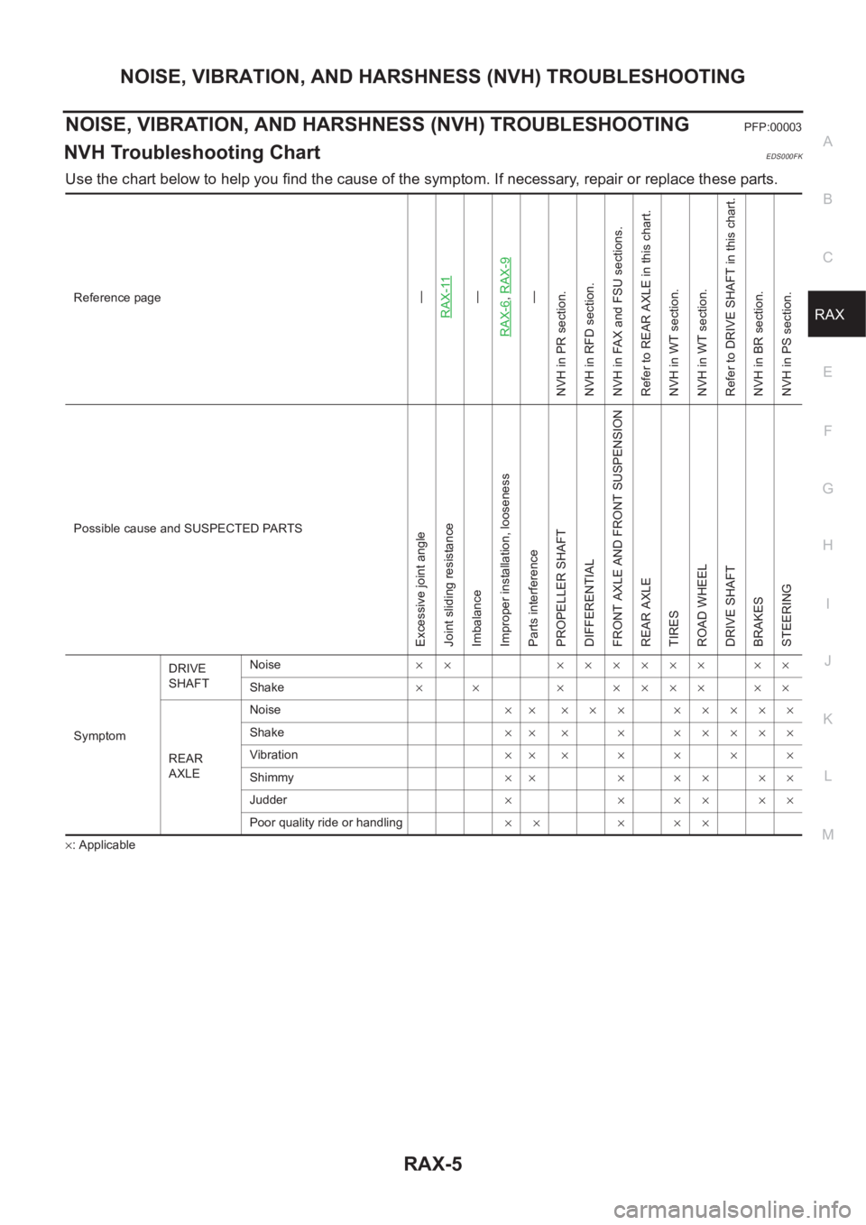
NOISE, VIBRATION, AND HARSHNESS (NVH) TROUBLESHOOTINGPFP:00003
NVH Troubleshooting ChartEDS000FK
Use the chart below to help you find the cause of the symptom. If necessary, repair or replace these parts.
×: ApplicableReference page
—
RAX-11—
RAX-6,RAX-9—
NVH in PR section.
NVH in RFD section.
NVH in FAX and FSU sections.
Refer to REAR AXLE in this chart.
NVH in WT section.
NVH in WT section.
Refer to DRIVE SHAFT in this chart.
NVH in BR section.
NVH in PS section.
Possible cause and SUSPECTED PARTS
Excessive joint angle
Joint sliding resistance
Imbalance
Improper installation, looseness
Parts interference
PROPELLER SHAFT
DIFFERENTIAL
FRONT AXLE AND FRONT SUSPENSION
REAR AXLE
TIRES
ROAD WHEEL
DRIVE SHAFT
BRAKES
STEERING
SymptomDRIVE
SHAFTNoise×× ×××××× ××
Shake×× ×××××××
REAR
AXLENoise×× ××× ×××××
Shake×× × × ×××××
Vibration×××××××
Shimmy×× × × × × ×
Judder××××××
Poor quality ride or handling×× × ××
Page 2973 of 3833
WHEEL HUB (4WD)
RAX-7
C
E
F
G
H
I
J
K
L
MA
B
RAX
2. Remove wheel hub lock nuts.
CAUTION:
Discard the old hub lock nuts; replace with new ones.
3. Remove brake caliper from axle housing and hang it up some-
where.
CAUTION:
Avoid depressing the brake pedal while the brake caliper is
removed.
4. Remove disc rotor and parking brake assembly from back plate
and axle housing.
5. Remove ABS wheel speed sensor from axle housing.
6. Remove axle housing from strut.
7. Remove nut and bolt from axle housing side of radius rod.
8. Remove nuts and bolts from axle housing sides of front and rear parallel links. Remove axle housing from
vehicle.
INSTALLATION
●Refer to component parts drawing for tightening torque. For installation, follow removal procedure in
reverse order.
Disassembly and AssemblyEDS00067
DISASSEMBLY
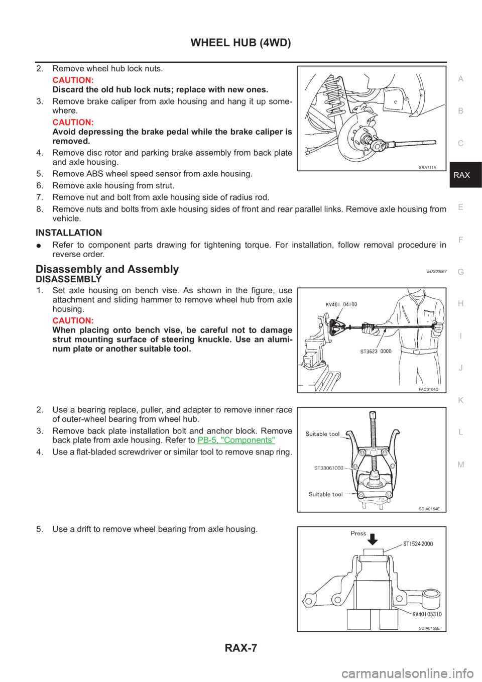
1. Set axle housing on bench vise. As shown in the figure, use
attachment and sliding hammer to remove wheel hub from axle
housing.
CAUTION:
When placing onto bench vise, be careful not to damage
strut mounting surface of steering knuckle. Use an alumi-
num plate or another suitable tool.
2. Use a bearing replace, puller, and adapter to remove inner race
of outer-wheel bearing from wheel hub.
3. Remove back plate installation bolt and anchor block. Remove
back plate from axle housing. Refer to PB-5, "
Components"
4. Use a flat-bladed screwdriver or similar tool to remove snap ring.
5. Use a drift to remove wheel bearing from axle housing.
SRA711A
FAC0104D
SDIA0154E
SDIA0155E
Page 3003 of 3833
SRS-1
SUPPLEMENTAL RESTRAINT SYSTEM (SRS)
H RESTRAINTS
CONTENTS
C
D
E
F
G
I
J
K
L
M
SECTION
A
B
SRS
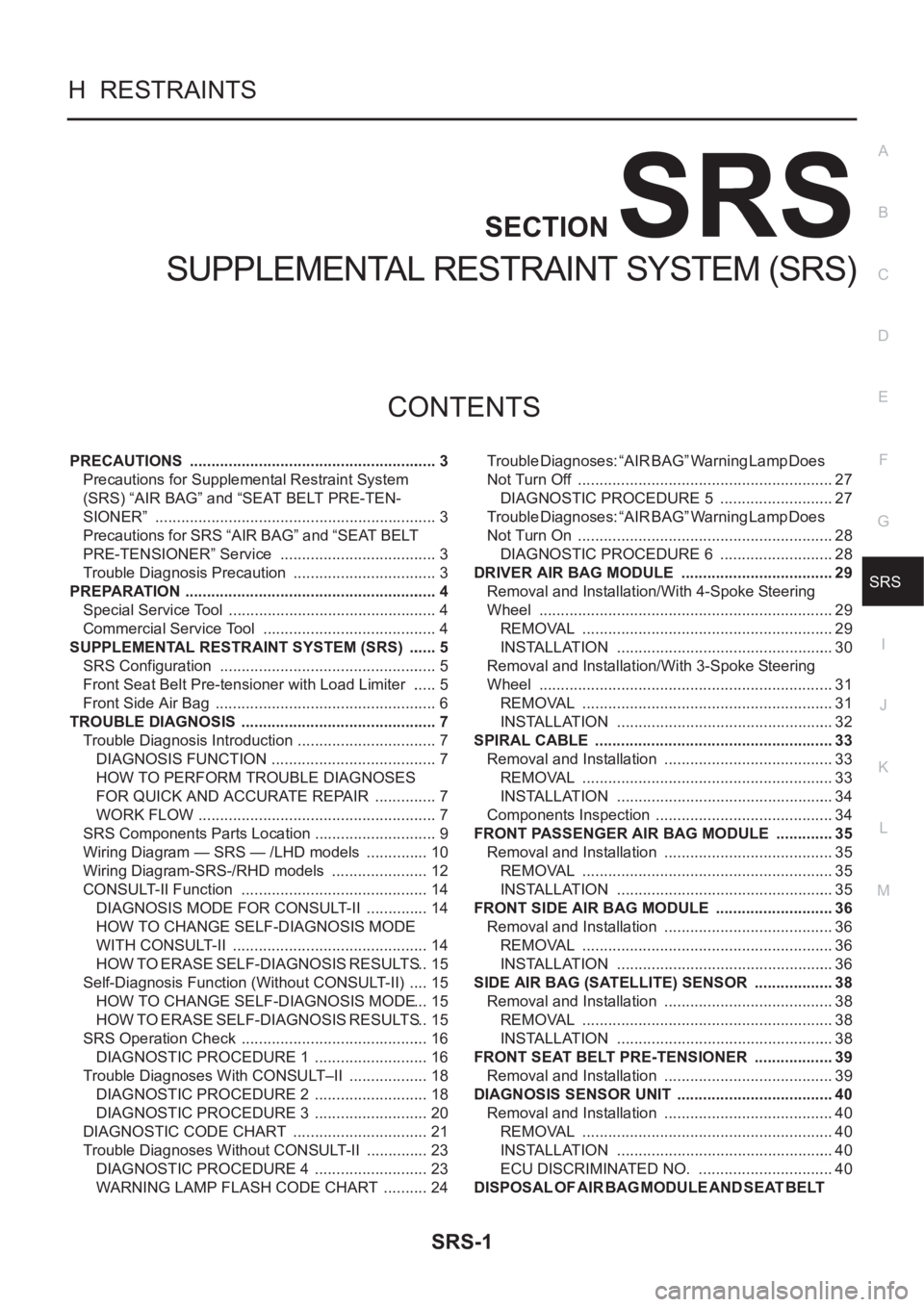
SUPPLEMENTAL RESTRAINT SYSTEM (SRS)
PRECAUTIONS .......................................................... 3
Precautions for Supplemental Restraint System
(SRS) “AIR BAG” and “SEAT BELT PRE-TEN-
SIONER” .................................................................. 3
Precautions for SRS “AIR BAG” and “SEAT BELT
PRE-TENSIONER” Service ..................................... 3
Trouble Diagnosis Precaution .................................. 3
PREPARATION ........................................................... 4
Special Service Tool ................................................. 4
Commercial Service Tool ......................................... 4
SUPPLEMENTAL RESTRAINT SYSTEM (SRS) ....... 5
SRS Configuration ................................................... 5
Front Seat Belt Pre-tensioner with Load Limiter ...... 5
Front Side Air Bag .................................................... 6
TROUBLE DIAGNOSIS .............................................. 7
Trouble Diagnosis Introduction ................................. 7
DIAGNOSIS FUNCTION ....................................... 7
HOW TO PERFORM TROUBLE DIAGNOSES
FOR QUICK AND ACCURATE REPAIR ............... 7
WORK FLOW ........................................................ 7
SRS Components Parts Location ............................. 9
Wiring Diagram — SRS — /LHD models ............... 10
Wiring Diagram-SRS-/RHD models ....................... 12
CONSULT-II Function ............................................ 14
DIAGNOSIS MODE FOR CONSULT-II ............... 14
HOW TO CHANGE SELF-DIAGNOSIS MODE
WITH CONSULT-II .............................................. 14
HOW TO ERASE SELF-DIAGNOSIS RESULTS ... 15
Self-Diagnosis Function (Without CONSULT-II) ..... 15
HOW TO CHANGE SELF-DIAGNOSIS MODE ... 15
HOW TO ERASE SELF-DIAGNOSIS RESULTS ... 15
SRS Operation Check ............................................ 16
DIAGNOSTIC PROCEDURE 1 ........................... 16
Trouble Diagnoses With CONSULT–II ................... 18
DIAGNOSTIC PROCEDURE 2 ........................... 18
DIAGNOSTIC PROCEDURE 3 ........................... 20
DIAGNOSTIC CODE CHART ................................ 21
Trouble Diagnoses Without CONSULT-II ............... 23
DIAGNOSTIC PROCEDURE 4 ........................... 23
WARNING LAMP FLASH CODE CHART ........... 24Trouble Diagnoses: “AIR BAG” Warning Lamp Does
Not Turn Off ............................................................ 27
DIAGNOSTIC PROCEDURE 5 ........................... 27
Trouble Diagnoses: “AIR BAG” Warning Lamp Does
Not Turn On ............................................................ 28
DIAGNOSTIC PROCEDURE 6 ........................... 28
DRIVER AIR BAG MODULE .................................... 29
Removal and Installation/With 4-Spoke Steering
Wheel ..................................................................... 29
REMOVAL ........................................................... 29
INSTALLATION ................................................... 30
Removal and Installation/With 3-Spoke Steering
Wheel ..................................................................
... 31
REMOVAL ........................................................... 31
INSTALLATION ................................................... 32
SPIRAL CABLE ........................................................ 33
Removal and Installation ........................................ 33
REMOVAL ........................................................... 33
INSTALLATION ................................................... 34
Components Inspection .......................................... 34
FRONT PASSENGER AIR BAG MODULE .............. 35
Removal and Installation ........................................ 35
REMOVAL ........................................................... 35
INSTALLATION ................................................... 35
FRONT SIDE AIR BAG MODULE ............................ 36
Removal and Installation ........................................ 36
REMOVAL ........................................................... 36
INSTALLATION ................................................... 36
SIDE AIR BAG (SATELLITE) SENSOR ................... 38
Removal and Installation ........................................ 38
REMOVAL ........................................................... 38
INSTALLATION ................................................... 38
FRONT SEAT BELT PRE-TENSIONER ................... 39
Removal and Installation ........................................ 39
DIAGNOSIS SENSOR UNIT ..................................... 40
Removal and Installation ........................................ 40
REMOVAL ........................................................... 40
INSTALLATION ................................................... 40
ECU DISCRIMINATED NO. ................................ 40
DISPOSAL OF AIR BAG MODULE AND SEAT BELT
Page 3005 of 3833
PRECAUTIONS
SRS-3
C
D
E
F
G
I
J
K
L
MA
B
SRS
PRECAUTIONSPFP:00001
Precautions for Supplemental Restraint System (SRS) “AIR BAG” and “SEAT
BELT PRE-TENSIONER”
EHS000QI
The Supplemental Restraint System such as “AIR BAG” and “SEAT BELT PRE-TENSIONER”, used along
with a front seat belt, helps to reduce the risk or severity of injury to the driver and front passenger for certain
types of collision. Information necessary to service the system safely is included in the SRS and SB section of
this Service Manual.
WARNING:
●To avoid rendering the SRS inoperative, which could increase the risk of personal injury or death
in the event of a collision which would result in air bag inflation, all maintenance must be per-
formed by an authorized NISSAN/INFINITI dealer.
●Improper maintenance, including incorrect removal and installation of the SRS, can lead to per-
sonal injury caused by unintentional activation of the system. For removal of Spiral Cable and Air
Bag Module, see the SRS section.
●Do not use electrical test equipment on any circuit related to the SRS unless instructed to in this
Service Manual. SRS wiring harnesses can be identified by yellow and/or orange harness connec-
tors.
Precautions for SRS “AIR BAG” and “SEAT BELT PRE-TENSIONER” ServiceEHS000BH
●Do not use electrical test equipment to check SRS circuits unless instructed to in this Service Manual.
●Before servicing the SRS, turn ignition switch “OFF”, disconnect both battery cables and wait at least 3
minutes.
For approximately 3 minutes after the cables is removed, it is still possible for the air bag and seat belt
pre-tensioner to deploy. Therefore, do not work on any SRS connectors or wires until at least 3 minutes
have passed.
●Diagnosis sensor unit must always be installed with their arrow marks “⇐” pointing towards the front of the
vehicle for proper operation. Also check diagnosis sensor unit for cracks, deformities or rust before instal-
lation and replace as required.
●The spiral cable must be aligned with the neutral position since its rotations are limited. Do not attempt to
turn steering wheel or column after removal of steering gear.
●Handle air bag module carefully. Always place driver and front passenger air bag modules with the pad
side facing upward and place front side air bag module standing with stud bolt side setting bottom.
●Conduct self-diagnosis to check entire SRS for proper function after replacing any components.
●After air bag inflates, the front instrument panel assembly should be replaced if damaged.
Trouble Diagnosis PrecautionEHS000BI
When you read wiring diagrams, refer to the followings:
●“HOW TO READ WIRING DIAGRAMS” in GI section
●PG-2, "POWER SUPPLY ROUTING" in PG section
When you perform trouble diagnosis, refer to the followings:
●“HOW TO FOLLOW TEST GROUP IN TROUBLE DIAGNOSIS” in GI section
●“HOW TO PERFORM EFFICIENT DIAGNOSIS FOR AN ELECTRICAL INCIDENT” in GI section
Check for any service bulletins before servicing the vehicle.
Page 3031 of 3833
DRIVER AIR BAG MODULE
SRS-29
C
D
E
F
G
I
J
K
L
MA
B
SRS
DRIVER AIR BAG MODULEPFP:K8510
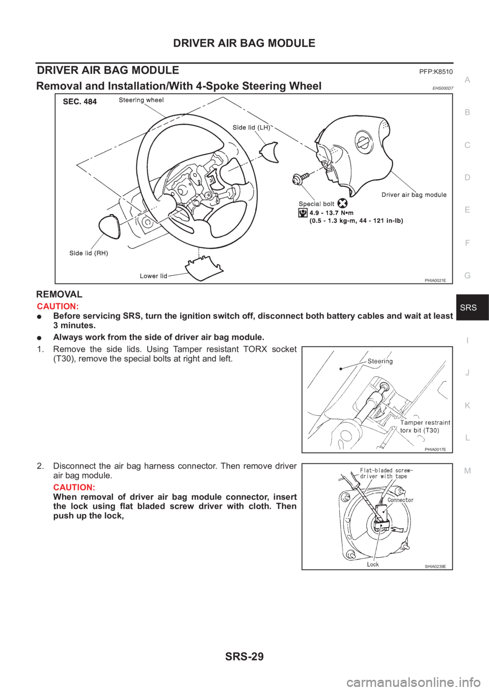
Removal and Installation/With 4-Spoke Steering WheelEHS000D7
REMOVAL
CAUTION:
●Before servicing SRS, turn the ignition switch off, disconnect both battery cables and wait at least
3 minutes.
●Always work from the side of driver air bag module.
1. Remove the side lids. Using Tamper resistant TORX socket
(T30), remove the special bolts at right and left.
2. Disconnect the air bag harness connector. Then remove driver
air bag module.
CAUTION:
When removal of driver air bag module connector, insert
the lock using flat bladed screw driver with cloth. Then
push up the lock,
PHIA0021E
PHIA0017E
SHIA0239E
Page 3033 of 3833
DRIVER AIR BAG MODULE
SRS-31
C
D
E
F
G
I
J
K
L
MA
B
SRS
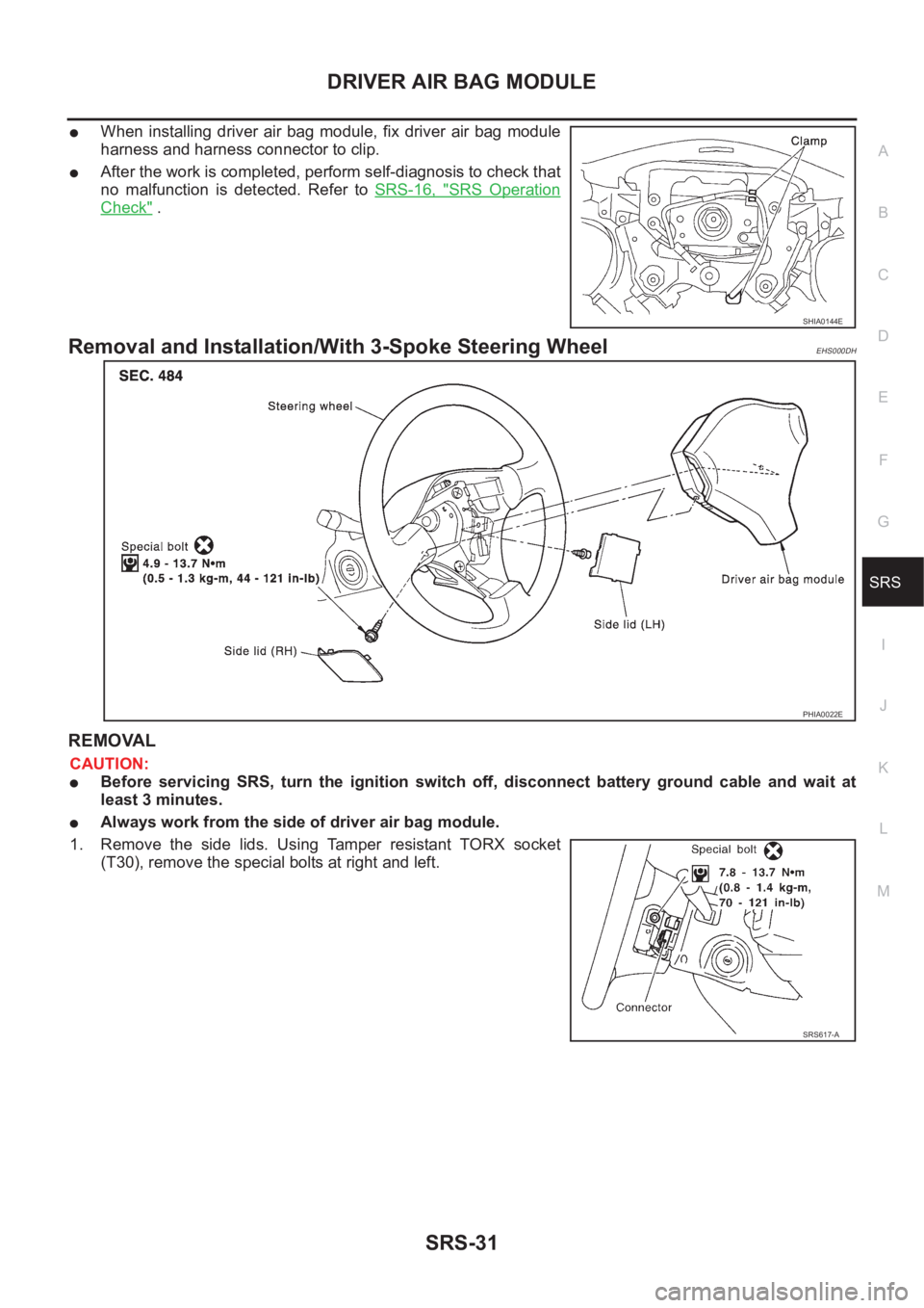
●When installing driver air bag module, fix driver air bag module
harness and harness connector to clip.
●After the work is completed, perform self-diagnosis to check that
no malfunction is detected. Refer to SRS-16, "
SRS Operation
Check" .
Removal and Installation/With 3-Spoke Steering WheelEHS000DH
REMOVAL
CAUTION:
●Before servicing SRS, turn the ignition switch off, disconnect battery ground cable and wait at
least 3 minutes.
●Always work from the side of driver air bag module.
1. Remove the side lids. Using Tamper resistant TORX socket
(T30), remove the special bolts at right and left.
SHIA0144E
PHIA0022E
SRS617-A
Page 3035 of 3833
SPIRAL CABLE
SRS-33
C
D
E
F
G
I
J
K
L
MA
B
SRS
SPIRAL CABLEPFP:25554
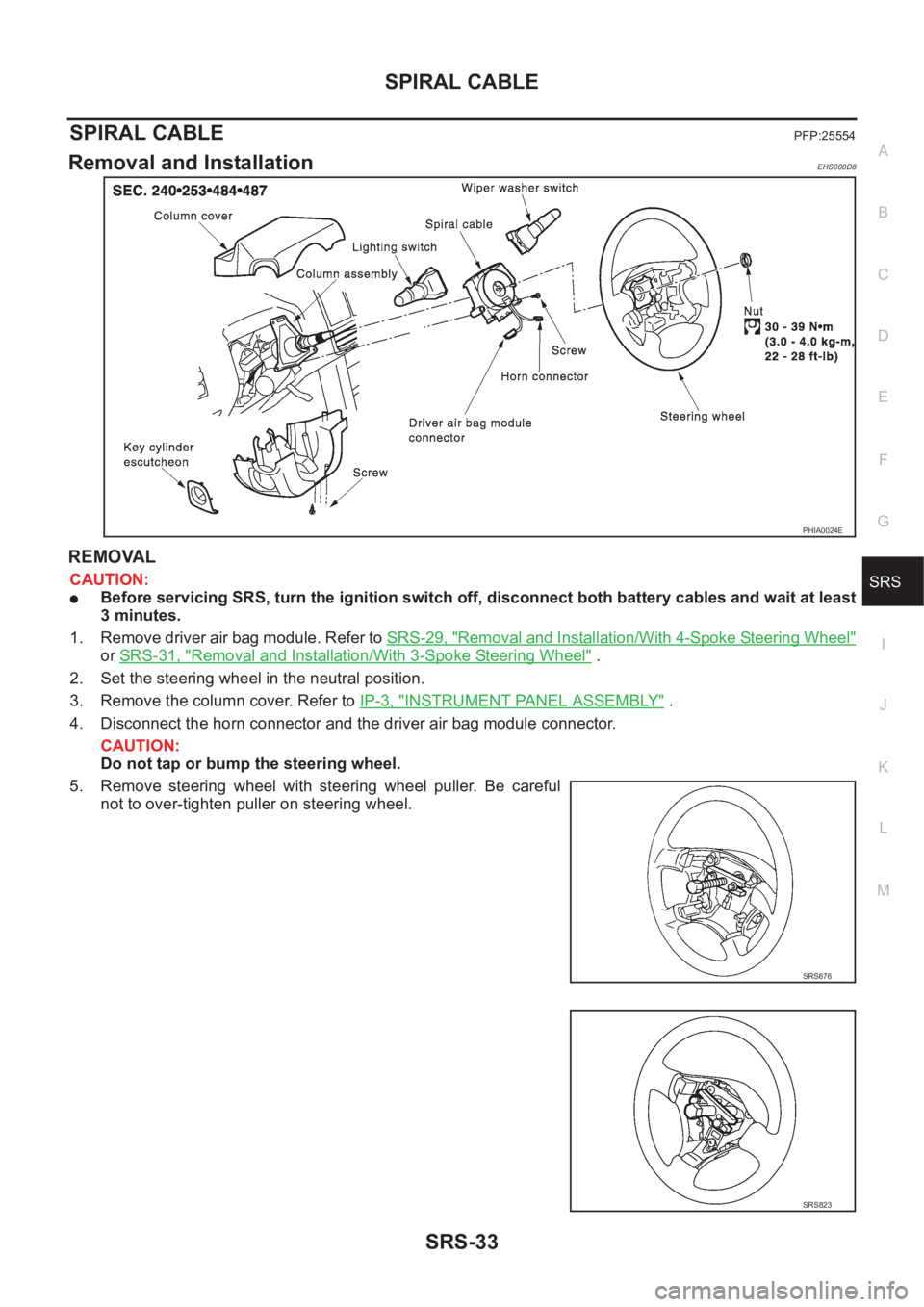
Removal and InstallationEHS000D8
REMOVAL
CAUTION:
●Before servicing SRS, turn the ignition switch off, disconnect both battery cables and wait at least
3 minutes.
1. Remove driver air bag module. Refer to SRS-29, "
Removal and Installation/With 4-Spoke Steering Wheel"
or SRS-31, "Removal and Installation/With 3-Spoke Steering Wheel" .
2. Set the steering wheel in the neutral position.
3. Remove the column cover. Refer to IP-3, "
INSTRUMENT PANEL ASSEMBLY" .
4. Disconnect the horn connector and the driver air bag module connector.
CAUTION:
Do not tap or bump the steering wheel.
5. Remove steering wheel with steering wheel puller. Be careful
not to over-tighten puller on steering wheel.
PHIA0024E
SRS676
SRS823
Page 3036 of 3833
SRS-34
SPIRAL CABLE
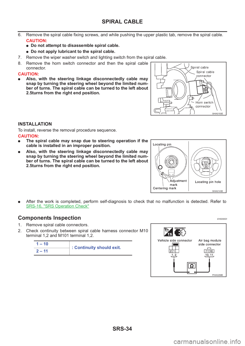
6. Remove the spiral cable fixing screws, and while pushing the upper plastic tab, remove the spiral cable.
CAUTION:
●Do not attempt to disassemble spiral cable.
●Do not apply lubricant to the spiral cable.
7. Remove the wiper washer switch and lighting switch from the spiral cable.
8. Remove the horn switch connector and then the spiral cable
connector.
CAUTION:
●Also, with the steering linkage disconnectedly cable may
snap by turning the steering wheel beyond the limited num-
ber of turns. The spiral cable can be turned to the left about
2.5turns from the right end position.
INSTALLATION
To install, reverse the removal procedure sequence.
CAUTION:
●The spiral cable may snap due to steering operation if the
cable is installed in an improper position.
●Also, with the steering linkage disconnectedly cable may
snap by turning the steering wheel beyond the limited num-
ber of turns. The spiral cable can be turned to the left about
2.5turns from the right end position.
●After the work is completed, perform self-diagnosis to check that no malfunction is detected. Refer to
SRS-16, "
SRS Operation Check"
Components InspectionEHS000DI
1. Remove spiral cable connectors.
2. Check continuity between spiral cable harness connector M10
terminal 1,2 and M101 terminal 1,2.
SHIA0193E
SHIA0145E
1 – 10
: Continuity should exit.
2 – 11
PHIA0298E