2001 NISSAN X-TRAIL steering wheel
[x] Cancel search: steering wheelPage 3049 of 3833

COLLISION DIAGNOSIS
SRS-47
C
D
E
F
G
I
J
K
L
MA
B
SRS
COLLISION DIAGNOSISPFP:00015
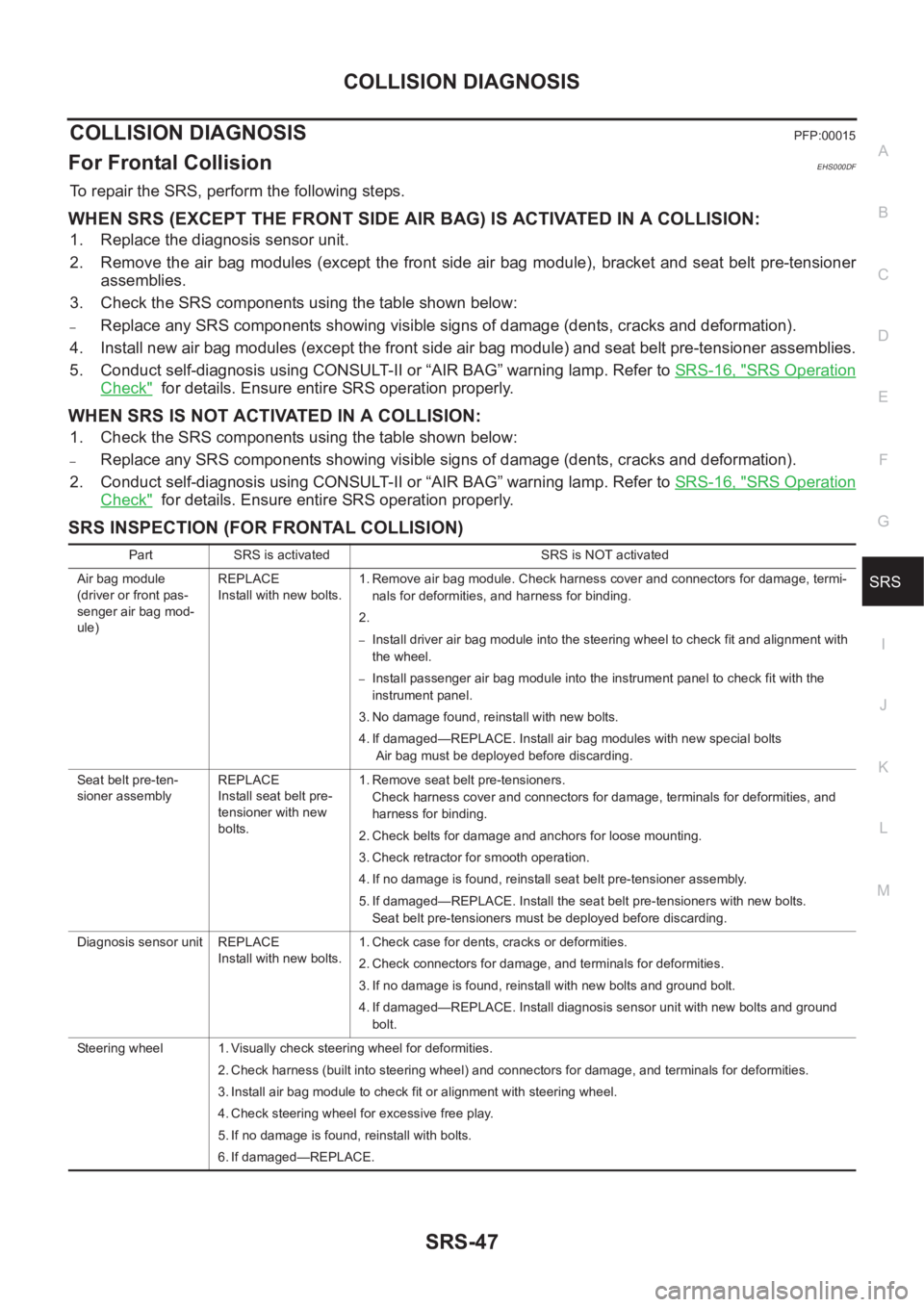
For Frontal CollisionEHS000DF
To repair the SRS, perform the following steps.
WHEN SRS (EXCEPT THE FRONT SIDE AIR BAG) IS ACTIVATED IN A COLLISION:
1. Replace the diagnosis sensor unit.
2. Remove the air bag modules (except the front side air bag module), bracket and seat belt pre-tensioner
assemblies.
3. Check the SRS components using the table shown below:
–Replace any SRS components showing visible signs of damage (dents, cracks and deformation).
4. Install new air bag modules (except the front side air bag module) and seat belt pre-tensioner assemblies.
5. Conduct self-diagnosis using CONSULT-II or “AIR BAG” warning lamp. Refer to SRS-16, "
SRS Operation
Check" for details. Ensure entire SRS operation properly.
WHEN SRS IS NOT ACTIVATED IN A COLLISION:
1. Check the SRS components using the table shown below:
–Replace any SRS components showing visible signs of damage (dents, cracks and deformation).
2. Conduct self-diagnosis using CONSULT-II or “AIR BAG” warning lamp. Refer to SRS-16, "
SRS Operation
Check" for details. Ensure entire SRS operation properly.
SRS INSPECTION (FOR FRONTAL COLLISION)
Part SRS is activated SRS is NOT activated
Air bag module
(driver or front pas-
senger air bag mod-
ule)REPLACE
Install with new bolts.1. Remove air bag module. Check harness cover and connectors for damage, termi-
nals for deformities, and harness for binding.
2.
–Install driver air bag module into the steering wheel to check fit and alignment with
the wheel.
–Install passenger air bag module into the instrument panel to check fit with the
instrument panel.
3. No damage found, reinstall with new bolts.
4. If damaged—REPLACE. Install air bag modules with new special bolts
Air bag must be deployed before discarding.
Seat belt pre-ten-
sioner assemblyREPLACE
Install seat belt pre-
tensioner with new
bolts.1. Remove seat belt pre-tensioners.
Check harness cover and connectors for damage, terminals for deformities, and
harness for binding.
2. Check belts for damage and anchors for loose mounting.
3. Check retractor for smooth operation.
4. If no damage is found, reinstall seat belt pre-tensioner assembly.
5. If damaged—REPLACE. Install the seat belt pre-tensioners with new bolts.
Seat belt pre-tensioners must be deployed before discarding.
Diagnosis sensor unit REPLACE
Install with new bolts.1. Check case for dents, cracks or deformities.
2. Check connectors for damage, and terminals for deformities.
3. If no damage is found, reinstall with new bolts and ground bolt.
4. If damaged—REPLACE. Install diagnosis sensor unit with new bolts and ground
bolt.
Steering wheel 1. Visually check steering wheel for deformities.
2. Check harness (built into steering wheel) and connectors for damage, and terminals for deformities.
3. Install air bag module to check fit or alignment with steering wheel.
4. Check steering wheel for excessive free play.
5. If no damage is found, reinstall with bolts.
6. If damaged—REPLACE.
Page 3050 of 3833

SRS-48
COLLISION DIAGNOSIS
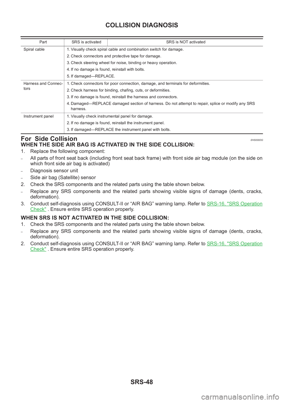
For Side Collision
EHS000DG
WHEN THE SIDE AIR BAG IS ACTIVATED IN THE SIDE COLLISION:
1. Replace the following component:
–All parts of front seat back (including front seat back frame) with front side air bag module (on the side on
which front side air bag is activated)
–Diagnosis sensor unit
–Side air bag (Satellite) sensor
2. Check the SRS components and the related parts using the table shown below.
–Replace any SRS components and the related parts showing visible signs of damage (dents, cracks,
deformation).
3. Conduct self-diagnosis using CONSULT-II or “AIR BAG” warning lamp. Refer to SRS-16, "
SRS Operation
Check" . Ensure entire SRS operation properly.
WHEN SRS IS NOT ACTIVATED IN THE SIDE COLLISION:
1. Check the SRS components and the related parts using the table shown below.
–Replace any SRS components and the related parts showing visible signs of damage (dents, cracks,
deformation).
2. Conduct self-diagnosis using CONSULT-II or “AIR BAG” warning lamp. Refer to SRS-16, "
SRS Operation
Check" . Ensure entire SRS operation properly.
Spiral cable 1. Visually check spiral cable and combination switch for damage.
2. Check connectors and protective tape for damage.
3. Check steering wheel for noise, binding or heavy operation.
4. If no damage is found, reinstall with bolts.
5. If damaged—REPLACE.
Harness and Connec-
tors1. Check connectors for poor connection, damage, and terminals for deformities.
2. Check harness for binding, chafing, cuts, or deformities.
3. If no damage is found, reinstall the harness and connectors.
4. Damaged—REPLACE damaged section of harness. Do not attempt to repair, splice or modify any SRS
harness.
Instrument panel 1. Visually check instrumental panel for damage.
2. If no damage is found, reinstall the instrument panel.
3. If damaged—REPLACE the instrument panel with bolts. Part SRS is activated SRS is NOT activated
Page 3663 of 3833

LAN-1
LAN SYSTEM
K ELECTRICAL
CONTENTS
C
D
E
F
G
H
I
J
L
M
SECTION
A
B
LAN
LAN SYSTEM
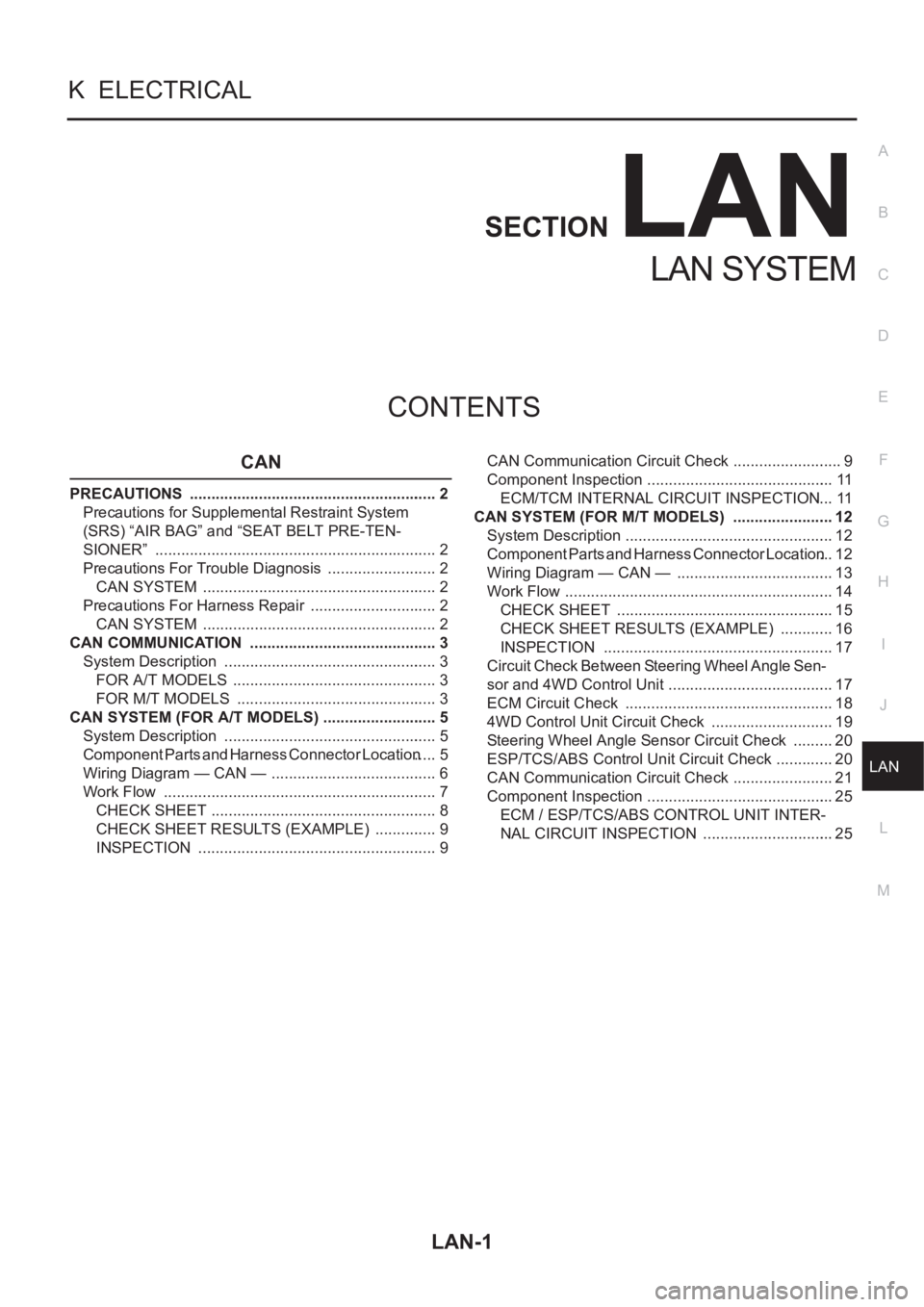
CAN
PRECAUTIONS .......................................................... 2
Precautions for Supplemental Restraint System
(SRS) “AIR BAG” and “SEAT BELT PRE-TEN-
SIONER” .................................................................. 2
Precautions For Trouble Diagnosis .......................... 2
CAN SYSTEM ....................................................... 2
Precautions For Harness Repair .............................. 2
CAN SYSTEM ....................................................... 2
CAN COMMUNICATION ............................................ 3
System Description .................................................. 3
FOR A/T MODELS ................................................ 3
FOR M/T MODELS ............................................... 3
CAN SYSTEM (FOR A/T MODELS) ........................... 5
System Description .................................................. 5
Component Parts and Harness Connector Location ..... 5
Wiring Diagram — CAN — ....................................... 6
Work Flow ................................................................ 7
CHECK SHEET ..................................................... 8
CHECK SHEET RESULTS (EXAMPLE) ............... 9
INSPECTION ........................................................ 9CAN Communication Circuit Check .......................... 9
Component Inspection ............................................ 11
ECM/TCM INTERNAL CIRCUIT INSPECTION ... 11
CAN SYSTEM (FOR M/T MODELS) ........................ 12
System Description ................................................. 12
Component Parts and Harness Connector Location ... 12
Wiring Diagram — CAN — ..................................... 13
Work Flow ............................................................... 14
CHECK SHEET ................................................... 15
CHECK SHEET RESULTS (EXAMPLE) ............. 16
INSPECTION ...................................................... 17
Circuit Check Between Steering Wheel Angle Sen-
sor and 4WD Control Unit ....................................... 17
ECM Circuit Check .............................................. ... 18
4WD Control Unit Circuit Check ............................. 19
Steering Wheel Angle Sensor Circuit Check .......... 20
ESP/TCS/ABS Control Unit Circuit Check .............. 20
CAN Communication Circuit Check ........................ 21
Component Inspection ............................................ 25
ECM / ESP/TCS/ABS CONTROL UNIT INTER-
NAL CIRCUIT INSPECTION ............................... 25
Page 3665 of 3833
![NISSAN X-TRAIL 2001 Service Repair Manual CAN COMMUNICATION
LAN-3
[CAN]
C
D
E
F
G
H
I
J
L
MA
B
LAN
CAN COMMUNICATIONPFP:23710
System DescriptionEKS001U3
CAN (Controller Area Network) is a serial communication line for real time application. I NISSAN X-TRAIL 2001 Service Repair Manual CAN COMMUNICATION
LAN-3
[CAN]
C
D
E
F
G
H
I
J
L
MA
B
LAN
CAN COMMUNICATIONPFP:23710
System DescriptionEKS001U3
CAN (Controller Area Network) is a serial communication line for real time application. I](/manual-img/5/57405/w960_57405-3664.png)
CAN COMMUNICATION
LAN-3
[CAN]
C
D
E
F
G
H
I
J
L
MA
B
LAN
CAN COMMUNICATIONPFP:23710
System DescriptionEKS001U3
CAN (Controller Area Network) is a serial communication line for real time application. It is an on-vehicle mul-
tiplex communication line with high data communication speed and excellent error detection ability. Many elec-
tronic control units are equipped onto a vehicle, and each control unit shares information and links with other
control units during operation (not independent). In CAN communication, control units are connected with 2
communication lines (CAN H line, CAN L line) allowing a high rate of information transmission with less wiring.
Each control unit transmits/receives data but selectively reads required data only.
FOR A/T MODELS
System diagram
Input/output signal chart
T: Transmit R: Receive
FOR M/T MODELS
System diagram
Input/output signal chart
T: Transmit R: Receive
SKIA0884E
Signals ECM TCM
Engine coolant temperature signal T R
Accelerator pedal position signal T R
A/T self-diagnosis signal R T
SKIA0885E
Signals ECMSteering wheel
angle sensor4WD control unitESP/ TCS / ABS
control unit
Engine speed signal T R R
Accelerator pedal position signal T R
ESP operation signal R R T
TCS operation signal R R T
ABS operation signal R R T
Stop lamp switch signalRT
Steering wheel angle sensor signal T R
ESP-OFF switch signalRT
Page 3666 of 3833
![NISSAN X-TRAIL 2001 Service Repair Manual LAN-4
[CAN]
CAN COMMUNICATION
Wheel speed sensor signalRT
4WD mode signalTR Signals ECMSteering wheel
angle sensor4WD control unitESP/ TCS / ABS
control unit NISSAN X-TRAIL 2001 Service Repair Manual LAN-4
[CAN]
CAN COMMUNICATION
Wheel speed sensor signalRT
4WD mode signalTR Signals ECMSteering wheel
angle sensor4WD control unitESP/ TCS / ABS
control unit](/manual-img/5/57405/w960_57405-3665.png)
LAN-4
[CAN]
CAN COMMUNICATION
Wheel speed sensor signalRT
4WD mode signalTR Signals ECMSteering wheel
angle sensor4WD control unitESP/ TCS / ABS
control unit
Page 3676 of 3833
![NISSAN X-TRAIL 2001 Service Repair Manual LAN-14
[CAN]
CAN SYSTEM (FOR M/T MODELS)
Work Flow
EKS002FN
1. Print all the data of “SELF-DIAG RESULTS” and “DATA MONITOR” for “ENGINE”, “ALL MODE 4WD”,
and “ABS” dis NISSAN X-TRAIL 2001 Service Repair Manual LAN-14
[CAN]
CAN SYSTEM (FOR M/T MODELS)
Work Flow
EKS002FN
1. Print all the data of “SELF-DIAG RESULTS” and “DATA MONITOR” for “ENGINE”, “ALL MODE 4WD”,
and “ABS” dis](/manual-img/5/57405/w960_57405-3675.png)
LAN-14
[CAN]
CAN SYSTEM (FOR M/T MODELS)
Work Flow
EKS002FN
1. Print all the data of “SELF-DIAG RESULTS” and “DATA MONITOR” for “ENGINE”, “ALL MODE 4WD”,
and “ABS” displayed on CONSULT-II. Refer to the following:
●EC-854, "DTC U1000 CAN COMMUNICATION LINE" (QR20 WITH EURO-OBD) for “ENGINE”
●EC-1199, "DTC U1000 CAN COMMUNICATION LINE" (QR20 WITHOUT EURO-OBD) for “ENGINE”
●EC-1448, "DTC U1000 CAN COMMUNICATION LINE" (YD) for “ENGINE”
●TF-53, "CAN COMMUNICATION SYSTEM" for “ALL MODE 4WD”
●BRC-110, "Inspection 15 CAN Communication Circuit, ESP/TCS/ABS Control Unit and Steering Wheel
Angle Sensor" for “ABS”
2. Attach the printed sheet of “SELF-DIAG RESULTS” and “DATA MONITOR” onto the check sheet. Refer to
LAN-15, "
CHECK SHEET" .
3. Based on the data monitor results, put “v” marks onto the items with “UNKWN” or “NG” in the check sheet
table. Refer to LAN-15, "
CHECK SHEET" .
NOTE:
If “NG” is displayed on “CAN COMM” for the diagnosed control unit, replace the control unit.
4. According to the check sheet results (example), start inspection. Refer to LAN-16, "
CHECK SHEET
RESULTS (EXAMPLE)" .
Page 3679 of 3833
![NISSAN X-TRAIL 2001 Service Repair Manual CAN SYSTEM (FOR M/T MODELS)
LAN-17
[CAN]
C
D
E
F
G
H
I
J
L
MA
B
LAN
INSPECTION
Proceed trouble diagnosis according to the check sheet results (example).
Case 1: Replace ECM.
Case 2: Replace ESP/TCS/AB NISSAN X-TRAIL 2001 Service Repair Manual CAN SYSTEM (FOR M/T MODELS)
LAN-17
[CAN]
C
D
E
F
G
H
I
J
L
MA
B
LAN
INSPECTION
Proceed trouble diagnosis according to the check sheet results (example).
Case 1: Replace ECM.
Case 2: Replace ESP/TCS/AB](/manual-img/5/57405/w960_57405-3678.png)
CAN SYSTEM (FOR M/T MODELS)
LAN-17
[CAN]
C
D
E
F
G
H
I
J
L
MA
B
LAN
INSPECTION
Proceed trouble diagnosis according to the check sheet results (example).
Case 1: Replace ECM.
Case 2: Replace ESP/TCS/ABS control unit.
Case 3: Replace 4WD control unit.
Case 4: Check harness between steering wheel angle sensor and 4WD control unit. Refer to LAN-17, "
Circuit
Check Between Steering Wheel Angle Sensor and 4WD Control Unit" .
Case 5: Check ECM circuit. Refer to LAN-18, "
ECM Circuit Check" .
Case 6: Check 4WD control unit circuit. Refer to LAN-19, "
4WD Control Unit Circuit Check" .
Case 7: Check Steering wheel angle sensor circuit. Refer to LAN-20, "
Steering Wheel Angle Sensor Circuit
Check" .
Case 8: Check ESP/TCS/ABS control unit circuit. Refer to LAN-20, "
ESP/TCS/ABS Control Unit Circuit
Check" .
Case 9: Check CAN communication circuit. Refer to LAN-21, "
CAN Communication Circuit Check" .
Circuit Check Between Steering Wheel Angle Sensor and 4WD Control UnitEKS002FO
1.CHECK CONNECTOR
1. Turn ignition switch OFF.
2. Check following terminals and connector for damage, bend and loose connection (control unit-side, sen-
sor-side and harness-side).
●4WD control unit.
●Steering wheel angle sensor.
●Between 4WD control unit and steering wheel angle sensor.
OK or NG
OK >> GO TO 2.
NG >> Repair terminal or connector.
SKIA0927E
Page 3680 of 3833
![NISSAN X-TRAIL 2001 Service Repair Manual LAN-18
[CAN]
CAN SYSTEM (FOR M/T MODELS)
2. CHECK HARNESS FOR OPEN CIRCUIT
1. Disconnect steering wheel angle sensor connector and harness connector M75.
2. Check continuity between steering wheel ang NISSAN X-TRAIL 2001 Service Repair Manual LAN-18
[CAN]
CAN SYSTEM (FOR M/T MODELS)
2. CHECK HARNESS FOR OPEN CIRCUIT
1. Disconnect steering wheel angle sensor connector and harness connector M75.
2. Check continuity between steering wheel ang](/manual-img/5/57405/w960_57405-3679.png)
LAN-18
[CAN]
CAN SYSTEM (FOR M/T MODELS)
2. CHECK HARNESS FOR OPEN CIRCUIT
1. Disconnect steering wheel angle sensor connector and harness connector M75.
2. Check continuity between steering wheel angle sensor harness
connector M81 terminals 4 (W), 5 (R) and harness connector
M75 terminals 8 (W), 19 (R).
OK or NG
OK >> GO TO 3.
NG >> Repair harness.
3. CHECK HARNESS FOR OPEN CIRCUIT
1. Disconnect 4WD control unit connector.
2. Check continuity between harness connector E116 terminals 8
(W), 19 (R) and 4WD control unit harness connector E122 termi-
nals 48 (W), 39 (R).
OK or NG
OK >> Reconnect all connectors to perform “SELF-DIAG
RESULTS” and “DATA MONITOR” for “ENGINE”, “ALL
MODE 4WD” and “ABS” displayed on CONSULT-II.
Refer to the following:
●EC-854, "DTC U1000 CAN COMMUNICATION LINE"
(QR20 WITH EURO-OBD) for “ENGINE”
●EC-1199, "DTC U1000 CAN COMMUNICATION LINE" (QR20 WITHOUT EURO-OBD) for
“ENGINE”
●EC-1448, "DTC U1000 CAN COMMUNICATION LINE" (YD) for “ENGINE”
●TF-53, "CAN COMMUNICATION SYSTEM" for “ALL MODE 4WD”
●BRC-110, "Inspection 15 CAN Communication Circuit, ESP/TCS/ABS Control Unit and Steer-
ing Wheel Angle Sensor" for “ABS”
NG >> Repair harness.
ECM Circuit CheckEKS002FQ
1. CHECK CONNECTOR
1. Turn ignition switch OFF.
2. Check following terminals and connector for damage, bend and loose connection (control module-side
and harness-side).
●ECM.
●Harness connector F41 (QR20DE engine models).
●Harness connector M61 (QR20DE engine models).
●Harness connector F29 (YD22DDTi engine models).
●Harness connector M64 (YD22DDTi engine models).
OK or NG
OK >> GO TO 2.
NG >> Repair terminal or connector.4 (W) – 8 (W) : Continuity should exist.
5 (R) – 19 (R) : Continuity should exist.
SKIA0928E
8 (W) – 48 (W) : Continuity should exist.
19 (R) – 39 (R) : Continuity should exist.
SKIA0929E