2001 NISSAN PICK-UP stop start
[x] Cancel search: stop startPage 930 of 1306
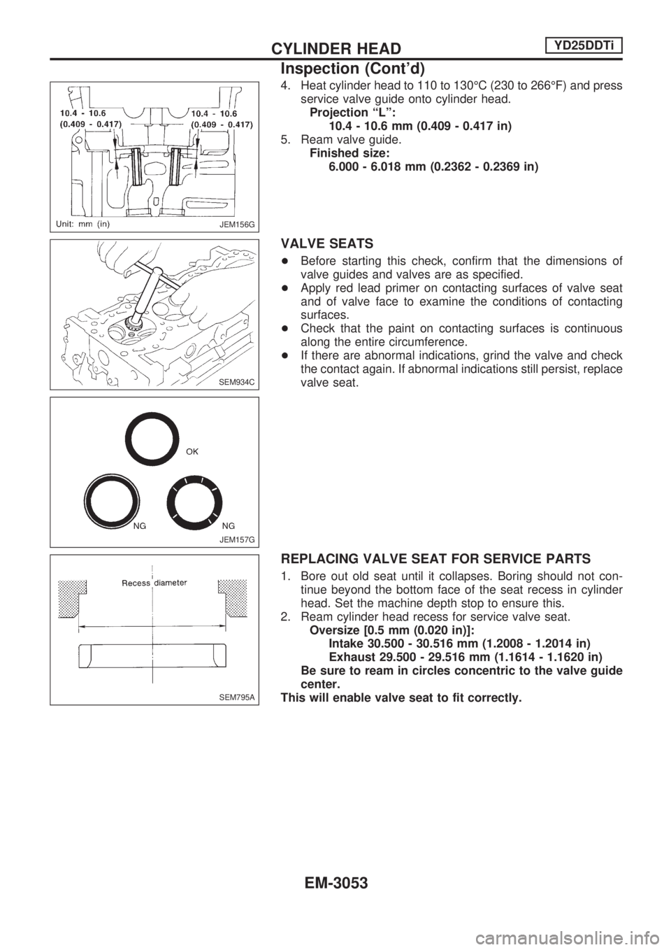
4. Heat cylinder head to 110 to 130ÉC (230 to 266ÉF) and press
service valve guide onto cylinder head.
Projection ªLº:
10.4 - 10.6 mm (0.409 - 0.417 in)
5. Ream valve guide.
Finished size:
6.000 - 6.018 mm (0.2362 - 0.2369 in)
VALVE SEATS
+Before starting this check, confirm that the dimensions of
valve guides and valves are as specified.
+Apply red lead primer on contacting surfaces of valve seat
and of valve face to examine the conditions of contacting
surfaces.
+Check that the paint on contacting surfaces is continuous
along the entire circumference.
+If there are abnormal indications, grind the valve and check
the contact again. If abnormal indications still persist, replace
valve seat.
REPLACING VALVE SEAT FOR SERVICE PARTS
1. Bore out old seat until it collapses. Boring should not con-
tinue beyond the bottom face of the seat recess in cylinder
head. Set the machine depth stop to ensure this.
2. Ream cylinder head recess for service valve seat.
Oversize [0.5 mm (0.020 in)]:
Intake 30.500 - 30.516 mm (1.2008 - 1.2014 in)
Exhaust 29.500 - 29.516 mm (1.1614 - 1.1620 in)
Be sure to ream in circles concentric to the valve guide
center.
This will enable valve seat to fit correctly.
JEM156G
SEM934C
JEM157G
SEM795A
CYLINDER HEADYD25DDTi
Inspection (Cont'd)
EM-3053
Page 1005 of 1306
Checking Refrigerant Leaks
CHECKING PROCEDURE
To prevent inaccurate or false readings, make sure there is
no refrigerant vapor or tobacco smoke in the vicinity of the
vehicle. Perform the leak test in calm area (low air/wind
movement) so that the leaking refrigerant is not dispersed.
1. Turn engine off.
2. Connect a suitable A/C manifold gauge set to the A/C ser-
vice ports.
3. Check if the A/C refrigerant pressure is at least 345 kPa
(3.452 bar, 3.52 kg/cm
2, 50 psi) above 16ÉC (61ÉF). If less
than specification, evacuate and recharge the system with
the specified amount of refrigerant.
NOTE: At temperatures below 16ÉC (61ÉF), leaks may not be
detected since the system may not reach 345 kPa
(3.452 bar, 3.52 kg/cm
2, 50 psi).
4. Conduct the leak test from the high side to the low side at
points
jathroughjn. Refer to HA-3030.
Perform a leak check for the following areas carefully. Clean
the component to be checked and move the leak detector
probe completely around the connection/component.
+Compressor
Check the fitting of high and low pressure hoses, relief valve
and shaft seal.
+Liquid tank
Check the pressure switch, tube fitting, weld seams and the
fusible plug mounts.
+Service valves
Check all around the service valves. Ensure service valve
caps are secured on the service valves (to prevent leaks).
NOTE: After removing A/C manifold gauge set from service
valves, wipe any residue from valves to prevent any
false readings by leak detector.
+Cooling unit (Evaporator)
Turn blower fan on ªHighº for at least 15 seconds to dissipate
any refrigerant trace in the cooling unit. Insert the leak detec-
tor probe into the drain hose immediately after stopping the
engine. (Keep the probe inserted for at least ten seconds.)
5. If a leak detector detects a leak, verify at least once by
blowing compressed air into area of suspected leak, then
repeat check.
6. Do not stop when one leak is found. Continue to check for
additional leaks at all system components.
7. Start engine.
8. Set the heater A/C control as follows:
a. A/C switch ON
b. Face mode
c. Recirculation switch ON
d. Max cold temperature
e. Fan speed high
9. Run engine at 1,500 rpm for at least 2 minutes.
10. Turn engine off and perform leak check again following steps
4 through 6 above.
SERVICE PROCEDURESMANUAL AND AUTO
HA-3031
Page 1065 of 1306
S
S/SIG - Wiring diagram ......................... EC-3375
SMJ (super multiple junction) ................ EL-3198
SRS - See Supplemental Restraint
System .............................................. RS-3003
START - Wiring diagram ....................... EL-3014
STOP/L - Wiring diagram ...................... EL-3043
Seat belt pre-tensioner disposal ........... RS-3011
Seat belt pre-tensioner ......................... RS-3003
Self-diagnostic results ................. EC-3429, 3430
Shift control (Transfer) ........................... TF-3005
Side air bag ........................................... RS-3003
Spiral cable ........................................... RS-3006
Spot lamp .............................................. EL-3055
Start signal ............................................ EC-3374
Starter .................................................... EL-3017
Starting system ...................................... EL-3014
Stop lamp .............................................. EL-3043
Supplemental Restraint System ........... RS-3003
Supplemental restraint system - Wiring
diagram ............................................. RS-3018
Symptom matrix chart ...... EC-3102, 3450, 3451
System readiness test (SRT) code ....... EC-3051
T
TAIL/L - Wiring diagram ........................ EL-3039
THEFT - Wiring diagram ....................... EL-3142
TP/SW - Wiring diagram ....................... EC-3303
TPS - Wiring diagram ................. EC-3174, 3185
TURN - Wiring diagram ......................... EL-3047
Tail lamp ................................................ EL-3039
Theft warning system ............................ EL-3142
Thermostat ............................................ LC-3014
Three way catalyst ................................ EC-3278Throttle bodies ...................................... EM-3008
Throttle chambers ................................. EM-3008
Throttle position sensor (TPS) .... EC-3170, 3182
Throttle position sensor adjustment ...... EC-3086
Throttle position switch ......................... EC-3301
Timing chain ......................................... EM-3021
Tire size .................................................. GI-3007
Turn signal lamp .................................... EL-3047
Two trip detection logic ......................... EC-3049
V
VSS - Wiring diagram ........................... EC-3292
Vacuum hose drawing (Engine
control) .............................................. EC-3022
Valve clearance .................................... EM-3060
Valve guide ........................................... EM-3052
Valve seat ............................................. EM-3053
Valve spring .......................................... EM-3055
Vehicle identification number ................. GI-3005
Vehicle speed sensor
(VSS) ............................ EC-3290, 3484, 3485
W
WARN - Wiring diagram ........................ EL-3083
WINDOW - Wiring diagram ................... EL-3123
Warning lamps ....................................... EL-3081
Water pump ........................................... LC-3012
Wheel size .............................................. GI-3007
Wide open & closed throttle position
switch ...................................... EC-3170, 3182
Wiring diagram (cell code) list ............... EL-3196
Wrist pin - See Piston pin inspection ... EM-3071
ALPHABETICAL INDEX
IDX-3005
Page 1112 of 1306
ELECTRICAL SYSTEM
SECTION
EL
MODIFICATION NOTICE:
+Wiring diagrams have been changed.
+Combination meter has been changed.
+Headlamp has been changed.
+Headlamp aiming control has been added.
+Headlamp washer has been added.
+A hazard reminder feature has been added to the multi-remote control system.
+NATS (Nissan Anti-Theft System) has been changed.
CONTENTS
PRECAUTIONS................................................... 3004
Supplemental Restraint System (SRS)²AIR
BAG²and²SEAT BELT PRE-TENSIONER².. 3004
POWER SUPPLY ROUTING............................... 3005
Schematic ........................................................ 3005
Wiring Diagram - POWER -............................. 3006
BATTERY............................................................. 3013
Service Data and Specifications (SDS) ........... 3013
STARTING SYSTEM........................................... 3014
Wiring Diagram - START -/M/T Models .......... 3014
Construction ..................................................... 3015
Service Data and Specifications (SDS) ........... 3017
CHARGING SYSTEM.......................................... 3018
Wiring Diagram - CHARGE -/Diesel Engine ... 3018
Wiring Diagram - CHARGE - (KA engine) ...... 3019
Construction ..................................................... 3020
Service Data and Specifications (SDS) ........... 3022
HEADLAMP - Conventional Type -................... 3023
Wiring Diagram - H/LAMP -/LHD Models ........ 3023
Wiring Diagram - H/LAMP -/RHD Models ....... 3025
Bulb Replacement............................................ 3027
Aiming Adjustment ........................................... 3027
Low Beam ........................................................ 3028
HEADLAMP - Daytime Light System -............. 3029
Wiring Diagram - DTRL - ................................. 3029
Bulb Replacement............................................ 3032
Aiming Adjustment ........................................... 3032
HEADLAMP - Dim-dip Lamp System -............. 3033Wiring Diagram - DIMDIP -.............................. 3033
Bulb Replacement............................................ 3036
Aiming Adjustment ........................................... 3036
HEADLAMP - Headlamp Aiming Control -....... 3037
Wiring Diagram - H/AIM - ................................ 3037
PARKING, LICENSE AND TAIL LAMPS........... 3039
Wiring Diagram - TAIL/L -/Except LHD Models
for Europe ........................................................ 3039
Wiring Diagram - TAIL/L -/LHD Models for
Europe.............................................................. 3041
STOP LAMP........................................................ 3043
Wiring Diagram - STOP/L - ............................. 3043
BACK-UP LAMP.................................................. 3044
Wiring Diagram - BACK/L -/M/T Models ......... 3044
REAR FOG LAMP............................................... 3045
Wiring Diagram - R/FOG -/LHD Models .......... 3045
Wiring Diagram - R/FOG -/RHD Models ......... 3046
TURN SIGNAL AND HAZARD WARNING
LAMPS................................................................. 3047
Wiring Diagram - TURN - ................................ 3047
Trouble Diagnoses ........................................... 3049
ILLUMINATION.................................................... 3050
Wiring Diagram - ILL -/LHD Models ................ 3050
Wiring Diagram - ILL -/RHD Models................ 3052
INTERIOR ROOM LAMP..................................... 3054
Wiring Diagram - ROOM/L - ............................ 3054
SPOT LAMP........................................................ 3055
Wiring Diagram - INT/L - ................................. 3055
EL
Page 1128 of 1306
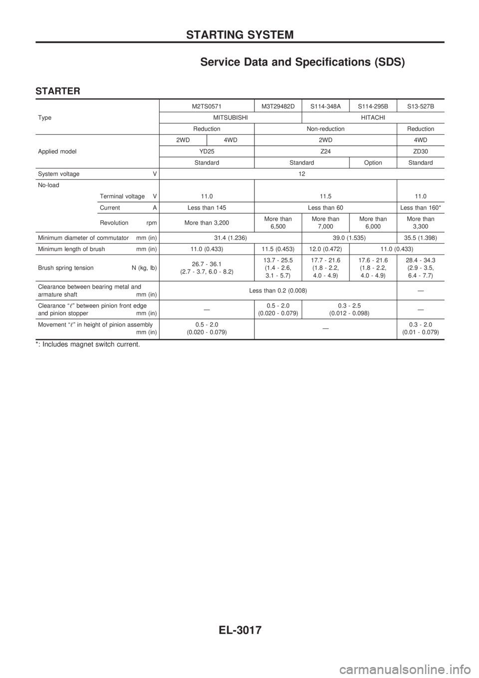
Service Data and Specifications (SDS)
STARTER
TypeM2TS0571 M3T29482D S114-348A S114-295B S13-527B
MITSUBISHI HITACHI
Reduction Non-reduction Reduction
Applied model2WD 4WD 2WD 4WD
YD25 Z24 ZD30
Standard Standard Option Standard
System voltage V 12
No-load
Terminal voltage V 11.0 11.5 11.0
Current A Less than 145 Less than 60 Less than 160*
Revolution rpm More than 3,200More than
6,500More than
7,000More than
6,000More than
3,300
Minimum diameter of commutator mm (in) 31.4 (1.236) 39.0 (1.535) 35.5 (1.398)
Minimum length of brush mm (in) 11.0 (0.433) 11.5 (0.453) 12.0 (0.472) 11.0 (0.433)
Brush spring tension N (kg, lb)26.7 - 36.1
(2.7 - 3.7, 6.0 - 8.2)13.7 - 25.5
(1.4 - 2.6,
3.1 - 5.7)17.7 - 21.6
(1.8 - 2.2,
4.0 - 4.9)17.6 - 21.6
(1.8 - 2.2,
4.0 - 4.9)28.4 - 34.3
(2.9 - 3.5,
6.4 - 7.7)
Clearance between bearing metal and
armature shaft mm (in)Less than 0.2 (0.008) Ð
Clearance ª!º between pinion front edge
and pinion stopper mm (in)Ð0.5 - 2.0
(0.020 - 0.079)0.3 - 2.5
(0.012 - 0.098)Ð
Movement ª!º in height of pinion assembly
mm (in)0.5 - 2.0
(0.020 - 0.079)Ð0.3 - 2.0
(0.01 - 0.079)
*: Includes magnet switch current.
STARTING SYSTEM
EL-3017
Page 1306 of 1306
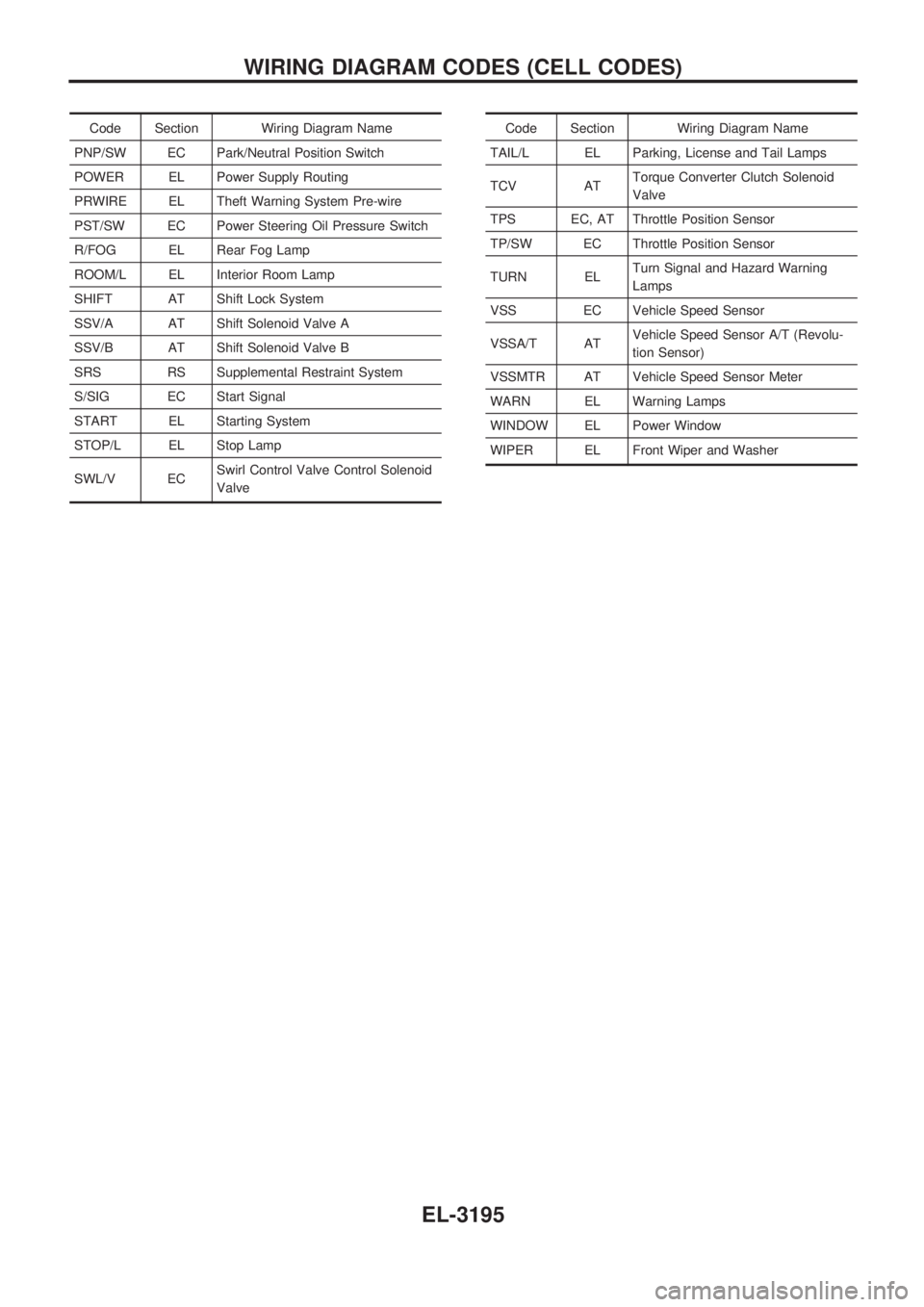
Code Section Wiring Diagram Name
PNP/SW EC Park/Neutral Position Switch
POWER EL Power Supply Routing
PRWIRE EL Theft Warning System Pre-wire
PST/SW EC Power Steering Oil Pressure Switch
R/FOG EL Rear Fog Lamp
ROOM/L EL Interior Room Lamp
SHIFT AT Shift Lock System
SSV/A AT Shift Solenoid Valve A
SSV/B AT Shift Solenoid Valve B
SRS RS Supplemental Restraint System
S/SIG EC Start Signal
START EL Starting System
STOP/L EL Stop Lamp
SWL/V ECSwirl Control Valve Control Solenoid
ValveCode Section Wiring Diagram Name
TAIL/L EL Parking, License and Tail Lamps
TCV ATTorque Converter Clutch Solenoid
Valve
TPS EC, AT Throttle Position Sensor
TP/SW EC Throttle Position Sensor
TURN ELTurn Signal and Hazard Warning
Lamps
VSS EC Vehicle Speed Sensor
VSSA/T ATVehicle Speed Sensor A/T (Revolu-
tion Sensor)
VSSMTR AT Vehicle Speed Sensor Meter
WARN EL Warning Lamps
WINDOW EL Power Window
WIPER EL Front Wiper and Washer
WIRING DIAGRAM CODES (CELL CODES)
EL-3195