2001 NISSAN PICK-UP sensor
[x] Cancel search: sensorPage 87 of 1306
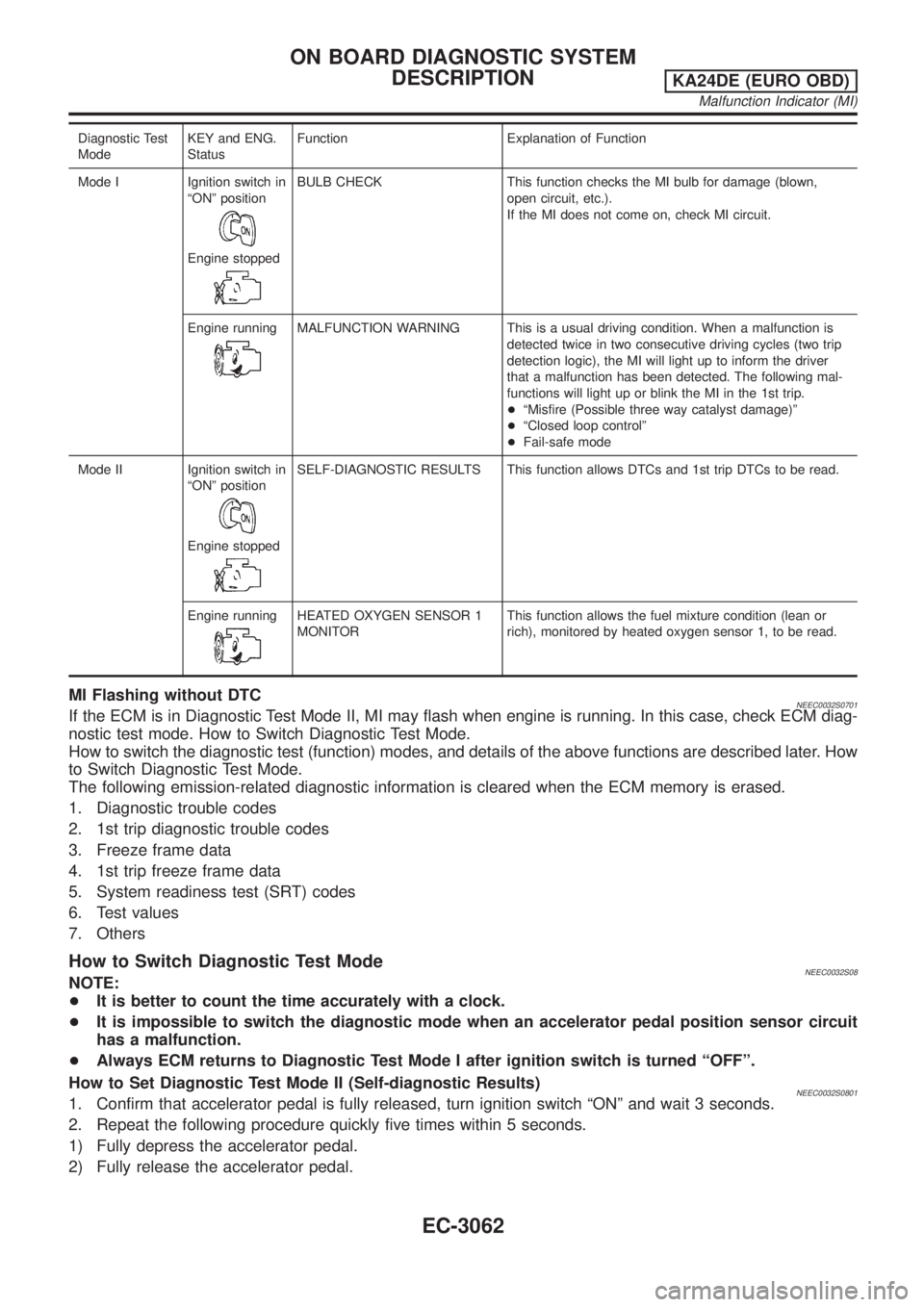
Diagnostic Test
ModeKEY and ENG.
StatusFunction Explanation of Function
Mode I Ignition switch in
ªONº position
Engine stopped
BULB CHECK This function checks the MI bulb for damage (blown,
open circuit, etc.).
If the MI does not come on, check MI circuit.
Engine running
MALFUNCTION WARNING This is a usual driving condition. When a malfunction is
detected twice in two consecutive driving cycles (two trip
detection logic), the MI will light up to inform the driver
that a malfunction has been detected. The following mal-
functions will light up or blink the MI in the 1st trip.
+ªMisfire (Possible three way catalyst damage)º
+ªClosed loop controlº
+Fail-safe mode
Mode II Ignition switch in
ªONº position
Engine stopped
SELF-DIAGNOSTIC RESULTS This function allows DTCs and 1st trip DTCs to be read.
Engine running
HEATED OXYGEN SENSOR 1
MONITORThis function allows the fuel mixture condition (lean or
rich), monitored by heated oxygen sensor 1, to be read.
MI Flashing without DTCNEEC0032S0701If the ECM is in Diagnostic Test Mode II, MI may flash when engine is running. In this case, check ECM diag-
nostic test mode. How to Switch Diagnostic Test Mode.
How to switch the diagnostic test (function) modes, and details of the above functions are described later. How
to Switch Diagnostic Test Mode.
The following emission-related diagnostic information is cleared when the ECM memory is erased.
1. Diagnostic trouble codes
2. 1st trip diagnostic trouble codes
3. Freeze frame data
4. 1st trip freeze frame data
5. System readiness test (SRT) codes
6. Test values
7. Others
How to Switch Diagnostic Test ModeNEEC0032S08NOTE:
+It is better to count the time accurately with a clock.
+It is impossible to switch the diagnostic mode when an accelerator pedal position sensor circuit
has a malfunction.
+Always ECM returns to Diagnostic Test Mode I after ignition switch is turned ªOFFº.
How to Set Diagnostic Test Mode II (Self-diagnostic Results)
NEEC0032S08011. Confirm that accelerator pedal is fully released, turn ignition switch ªONº and wait 3 seconds.
2. Repeat the following procedure quickly five times within 5 seconds.
1) Fully depress the accelerator pedal.
2) Fully release the accelerator pedal.
ON BOARD DIAGNOSTIC SYSTEM
DESCRIPTION
KA24DE (EURO OBD)
Malfunction Indicator (MI)
EC-3062
Page 88 of 1306
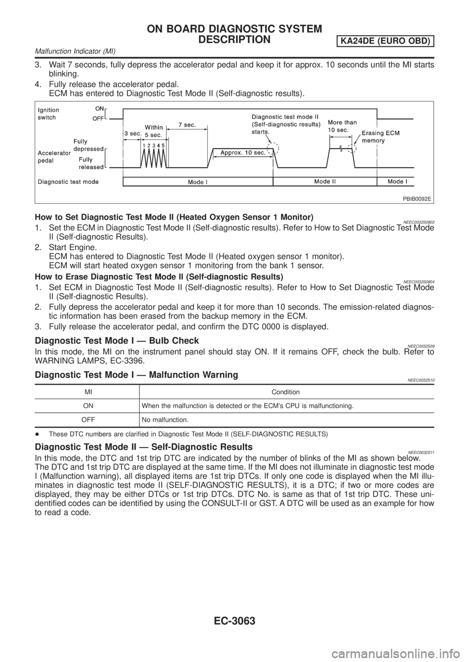
3. Wait 7 seconds, fully depress the accelerator pedal and keep it for approx. 10 seconds until the MI starts
blinking.
4. Fully release the accelerator pedal.
ECM has entered to Diagnostic Test Mode II (Self-diagnostic results).
PBIB0092E
How to Set Diagnostic Test Mode II (Heated Oxygen Sensor 1 Monitor)NEEC0032S08021. Set the ECM in Diagnostic Test Mode II (Self-diagnostic results). Refer to How to Set Diagnostic Test Mode
II (Self-diagnostic Results).
2. Start Engine.
ECM has entered to Diagnostic Test Mode II (Heated oxygen sensor 1 monitor).
ECM will start heated oxygen sensor 1 monitoring from the bank 1 sensor.
How to Erase Diagnostic Test Mode II (Self-diagnostic Results)
NEEC0032S08041. Set ECM in Diagnostic Test Mode II (Self-diagnostic results). Refer to How to Set Diagnostic Test Mode
II (Self-diagnostic Results).
2. Fully depress the accelerator pedal and keep it for more than 10 seconds. The emission-related diagnos-
tic information has been erased from the backup memory in the ECM.
3. Fully release the accelerator pedal, and confirm the DTC 0000 is displayed.
Diagnostic Test Mode I Ð Bulb CheckNEEC0032S09In this mode, the MI on the instrument panel should stay ON. If it remains OFF, check the bulb. Refer to
WARNING LAMPS, EC-3396.
Diagnostic Test Mode I Ð Malfunction WarningNEEC0032S10
MI Condition
ON When the malfunction is detected or the ECM's CPU is malfunctioning.
OFF No malfunction.
+These DTC numbers are clarified in Diagnostic Test Mode II (SELF-DIAGNOSTIC RESULTS)
Diagnostic Test Mode II Ð Self-Diagnostic ResultsNEEC0032S11In this mode, the DTC and 1st trip DTC are indicated by the number of blinks of the MI as shown below.
The DTC and 1st trip DTC are displayed at the same time. If the MI does not illuminate in diagnostic test mode
I (Malfunction warning), all displayed items are 1st trip DTCs. If only one code is displayed when the MI illu-
minates in diagnostic test mode II (SELF-DIAGNOSTIC RESULTS), it is a DTC; if two or more codes are
displayed, they may be either DTCs or 1st trip DTCs. DTC No. is same as that of 1st trip DTC. These uni-
dentified codes can be identified by using the CONSULT-II or GST. A DTC will be used as an example for how
to read a code.
ON BOARD DIAGNOSTIC SYSTEM
DESCRIPTION
KA24DE (EURO OBD)
Malfunction Indicator (MI)
EC-3063
Page 89 of 1306

SEC687C
A particular trouble code can be identified by the number of four-digit numeral flashes. The ªzeroº is indicated
by the number of ten flashes. The length of time the 1,000th-digit numeral flashes on and off is 1.2 seconds
consisting of an ON (0.6-second) - OFF (0.6-second) cycle.
The 100th-digit numeral and lower digit numerals consist of a 0.3-second ON and 0.3-second OFF cycle.
A change from one digit numeral to another occurs at an interval of 1.0-second OFF. In other words, the later
numeral appears on the display 1.3 seconds after the former numeral has disappeared.
A change from one trouble code to another occurs at an interval of 1.8-second OFF.
In this way, all the detected malfunctions are classified by their DTC numbers. The DTC ª0000º refers to no
malfunction. (See ªTROUBLE DIAGNOSIS Ð INDEXº, EC-3009.)
How to Erase Diagnostic Test Mode II (Self-diagnostic Results)
NEEC0032S1101The DTC can be erased from the back up memory in the ECM by depressing accelerator pedal. Refer to How
to Switch Diagnostic Test Mode.
+If the battery is disconnected, the DTC will be lost from the backup memory after approx 24 hours.
+Be careful not to erase the stored memory before starting trouble diagnoses.
Diagnostic Test Mode II Ð Heated Oxygen Sensor 1 MonitorNEEC0032S12In this mode, the MI displays the condition of the fuel mixture (lean or rich) which is monitored by the heated
oxygen sensor 1.
MI Fuel mixture condition in the exhaust gas Air fuel ratio feedback control condition
ON Lean
Closed loop system
OFF Rich
*Remains ON or OFF Any condition Open loop system
*: Maintains conditions just before switching to open loop.
To check the heated oxygen sensor 1 function, start engine in the Diagnostic Test Mode II and warm it up until
engine coolant temperature indicator points to the middle of the gauge.
Next run engine at about 2,000 rpm for about 2 minutes under no-load conditions. Then make sure that the
MI comes ON more than 5 times within 10 seconds with engine running at 2,000 rpm under no-load.
OBD System Operation ChartNEEC0033RELATIONSHIP BETWEEN MI, DTC, 1ST TRIP DTC AND DETECTABLE ITEMSNEEC0033S01+When a malfunction is detected for the first time, the 1st trip DTC and the 1st trip freeze frame data are
stored in the ECM memory.
+When the same malfunction is detected in two consecutive trips, the DTC and the freeze frame data are
stored in the ECM memory, and the MI will come on. For details, refer to ªTwo Trip Detection Logicº on
EC-3049.
ON BOARD DIAGNOSTIC SYSTEM
DESCRIPTION
KA24DE (EURO OBD)
Malfunction Indicator (MI)
EC-3064
Page 96 of 1306
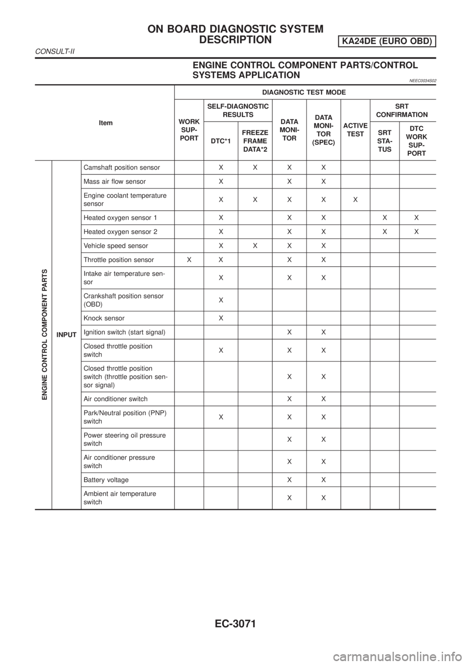
ENGINE CONTROL COMPONENT PARTS/CONTROL
SYSTEMS APPLICATION
NEEC0034S02
ItemDIAGNOSTIC TEST MODE
WORK
SUP-
PORTSELF-DIAGNOSTIC
RESULTS
DATA
MONI-
TORDATA
MONI-
TOR
(SPEC)ACTIVE
TESTSRT
CONFIRMATION
DTC*1FREEZE
FRAME
DATA*2SRT
STA-
TUSDTC
WORK
SUP-
PORT
ENGINE CONTROL COMPONENT PARTS
INPUTCamshaft position sensorXXXX
Mass air flow sensor X X X
Engine coolant temperature
sensorXXXXX
Heated oxygen sensor 1 X X X X X
Heated oxygen sensor 2 X X X X X
Vehicle speed sensorXXXX
Throttle position sensor X X X X
Intake air temperature sen-
sorXXX
Crankshaft position sensor
(OBD)X
Knock sensor X
Ignition switch (start signal) X X
Closed throttle position
switchXXX
Closed throttle position
switch (throttle position sen-
sor signal)XX
Air conditioner switch X X
Park/Neutral position (PNP)
switchXXX
Power steering oil pressure
switchXX
Air conditioner pressure
switchXX
Battery voltage X X
Ambient air temperature
switchXX
ON BOARD DIAGNOSTIC SYSTEM
DESCRIPTION
KA24DE (EURO OBD)
CONSULT-II
EC-3071
Page 97 of 1306
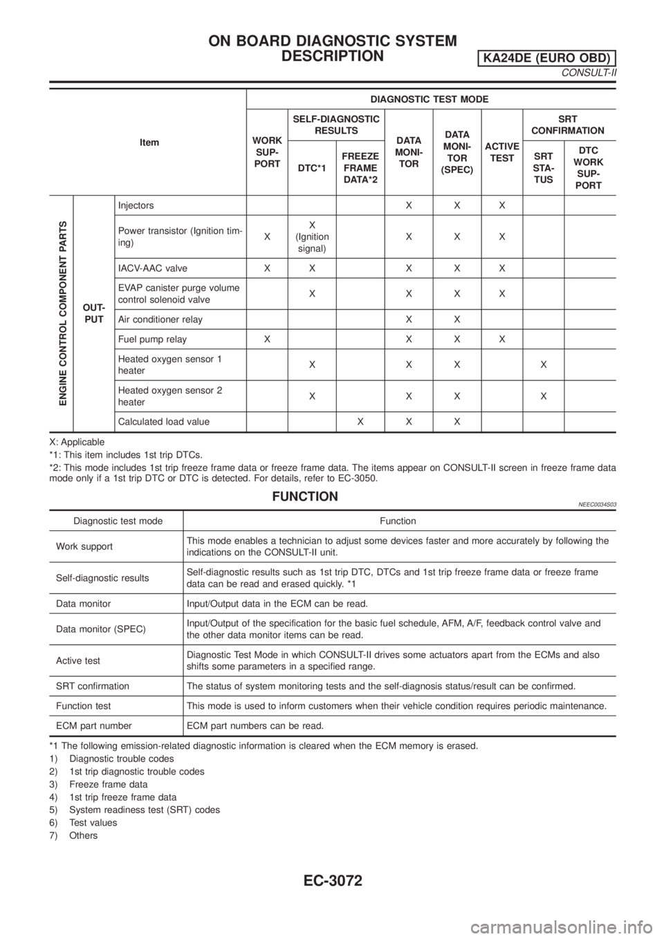
ItemDIAGNOSTIC TEST MODE
WORK
SUP-
PORTSELF-DIAGNOSTIC
RESULTS
DATA
MONI-
TORDATA
MONI-
TOR
(SPEC)ACTIVE
TESTSRT
CONFIRMATION
DTC*1FREEZE
FRAME
DATA*2SRT
STA-
TUSDTC
WORK
SUP-
PORT
ENGINE CONTROL COMPONENT PARTS
OUT-
PUTInjectors X X X
Power transistor (Ignition tim-
ing)XX
(Ignition
signal)XXX
IACV-AAC valve X X X X X
EVAP canister purge volume
control solenoid valveXXXX
Air conditioner relay X X
Fuel pump relay X X X X
Heated oxygen sensor 1
heaterXXXX
Heated oxygen sensor 2
heaterXXXX
Calculated load value X X X
X: Applicable
*1: This item includes 1st trip DTCs.
*2: This mode includes 1st trip freeze frame data or freeze frame data. The items appear on CONSULT-II screen in freeze frame data
mode only if a 1st trip DTC or DTC is detected. For details, refer to EC-3050.
FUNCTIONNEEC0034S03
Diagnostic test mode Function
Work supportThis mode enables a technician to adjust some devices faster and more accurately by following the
indications on the CONSULT-II unit.
Self-diagnostic resultsSelf-diagnostic results such as 1st trip DTC, DTCs and 1st trip freeze frame data or freeze frame
data can be read and erased quickly. *1
Data monitor Input/Output data in the ECM can be read.
Data monitor (SPEC)Input/Output of the specification for the basic fuel schedule, AFM, A/F, feedback control valve and
the other data monitor items can be read.
Active testDiagnostic Test Mode in which CONSULT-II drives some actuators apart from the ECMs and also
shifts some parameters in a specified range.
SRT confirmation The status of system monitoring tests and the self-diagnosis status/result can be confirmed.
Function test This mode is used to inform customers when their vehicle condition requires periodic maintenance.
ECM part number ECM part numbers can be read.
*1 The following emission-related diagnostic information is cleared when the ECM memory is erased.
1) Diagnostic trouble codes
2) 1st trip diagnostic trouble codes
3) Freeze frame data
4) 1st trip freeze frame data
5) System readiness test (SRT) codes
6) Test values
7) Others
ON BOARD DIAGNOSTIC SYSTEM
DESCRIPTION
KA24DE (EURO OBD)
CONSULT-II
EC-3072
Page 98 of 1306
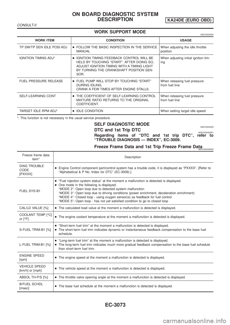
WORK SUPPORT MODENEEC0034S04
WORK ITEM CONDITION USAGE
TP SW/TP SEN IDLE POSI ADJ+FOLLOW THE BASIC INSPECTION IN THE SERVICE
MANUALWhen adjusting the idle throttle
position
IGNITION TIMING ADJ*+IGNITION TIMING FEEDBACK CONTROL WILL BE
HELD BY TOUCHING ªSTARTº. AFTER DOING SO,
ADJUST IGNITION TIMING WITH A TIMING LIGHT
BY TURNING THE CRANKSHAFT POSITION SEN-
SOR.When adjusting initial ignition tim-
ing
FUEL PRESSURE RELEASE+FUEL PUMP WILL STOP BY TOUCHING ªSTARTº
DURING IDLING.
CRANK A FEW TIMES AFTER ENGINE STALLS.When releasing fuel pressure
from fuel line
SELF-LEARNING CONT+THE COEFFICIENT OF SELF-LEARNING CONTROL
MIXTURE RATIO RETURNS TO THE ORIGINAL
COEFFICIENT.When releasing fuel pressure
from fuel line
TARGET IDLE RPM ADJ*+IDLE CONDITION When setting target idle speed
*: This function is not necessary in the usual service procedure.
SELF DIAGNOSTIC MODENEEC0034S05DTC and 1st Trip DTCNEEC0034S0501Regarding items of ªDTC and 1st trip DTCº, refer to
ªTROUBLE DIAGNOSIS Ð INDEXº, EC-3009.
Freeze Frame Data and 1st Trip Freeze Frame DataNEEC0034S0502
Freeze frame data
item*Description
DIAG TROUBLE
CODE
[PXXXX]+Engine Control component part/control system has a trouble code, it is displayed as ªPXXXXº. [Refer to
ªAlphabetical & P No. Index for DTCº (EC-3009).]
FUEL SYS-B1+ªFuel injection system statusº at the moment a malfunction is detected is displayed.
+One mode in the following is displayed.
ªMODE 2º: Open loop due to detected system malfunction
ªMODE 3º: Open loop due to driving conditions (power enrichment, deceleration enrichment)
ªMODE 4º: Closed loop - using oxygen sensor(s) as feedback for fuel control
ªMODE 5º: Open loop - has not yet satisfied condition to go to closed loop
CAL/LD VALUE [%]+The calculated load value at the moment a malfunction is detected is displayed.
COOLANT TEMP [ÉC]
or [ÉF]+The engine coolant temperature at the moment a malfunction is detected is displayed.
S-FUEL TRIM-B1 [%]+ªShort-term fuel trimº at the moment a malfunction is detected is displayed.
+The short-term fuel trim indicates dynamic or instantaneous feedback compensation to the base fuel
schedule.
L-FUEL TRIM-B1 [%]+ªLong-term fuel trimº at the moment a malfunction is detected is displayed.
+The long-term fuel trim indicates much more gradual feedback compensation to the base fuel schedule
than short-term fuel trim.
ENGINE SPEED
[rpm]+The engine speed at the moment a malfunction is detected is displayed.
VEHICLE SPEED
[km/h] or [mph]+The vehicle speed at the moment a malfunction is detected is displayed.
ABSOL TH-P/S [%]+The throttle valve opening angle at the moment a malfunction is detected is displayed.
B/FUEL SCHDL
[msec]+The base fuel schedule at the moment a malfunction is detected is displayed.
ON BOARD DIAGNOSTIC SYSTEM
DESCRIPTION
KA24DE (EURO OBD)
CONSULT-II
EC-3073
Page 99 of 1306
![NISSAN PICK-UP 2001 Repair Manual Freeze frame data
item*Description
INT/A TEMP SE [ÉC]
or [ÉF]+The intake air temperature at the moment a malfunction is detected is displayed.
*: The items are the same as those of 1st trip freeze f NISSAN PICK-UP 2001 Repair Manual Freeze frame data
item*Description
INT/A TEMP SE [ÉC]
or [ÉF]+The intake air temperature at the moment a malfunction is detected is displayed.
*: The items are the same as those of 1st trip freeze f](/manual-img/5/57372/w960_57372-98.png)
Freeze frame data
item*Description
INT/A TEMP SE [ÉC]
or [ÉF]+The intake air temperature at the moment a malfunction is detected is displayed.
*: The items are the same as those of 1st trip freeze frame data.
DATA MONITOR MODENEEC0034S06
Monitored item [Unit]ECM
input
signalsMain
signalsDescription Remarks
ENG SPEED [rpm]jj+Indicates the engine speed computed
from the REF signal (180É signal) of
the camshaft position sensor.+Accuracy becomes poor if engine
speed drops below the idle rpm.
+If the signal is interrupted while the
engine is running, an abnormal value
may be indicated.
MAS A/F SE-B1 [V]jj+The signal voltage of the mass air flow
sensor is displayed.+When the engine is stopped, a cer-
tain value is indicated.
B/FUEL SCHDL [msec]j+ªBase fuel scheduleº indicates the fuel
injection pulse width programmed into
ECM, prior to any learned on board
correction.
A/F ALPHA-B1 [%]j+Indicates the mean value of the air-fuel
ratio feedback correction factor per
cycle.+When the engine is stopped, a cer-
tain value is indicated.
+This data also includes the data for
the air-fuel ratio learning control.
COOLAN TEMP/S
[ÉC] or [ÉF]jj+The engine coolant temperature (deter-
mined by the signal voltage of the
engine coolant temperature sensor) is
displayed.+When the engine coolant temperature
sensor is open or short-circuited,
ECM enters fail-safe mode. The
engine coolant temperature deter-
mined by the ECM is displayed.
HO2S1 (B1) [V]jj+The signal voltage of the heated oxy-
gen sensor 1 is displayed.
HO2S2 (B1) [V]j+The signal voltage of the heated oxy-
gen sensor 2 is displayed.
HO2S1 MNTR (B1)
[RICH/LEAN]jj+Display of heated oxygen sensor 1 sig-
nal during air-fuel ratio feedback con-
trol:
RICH ... means the mixture became
ªrichº, and control is being affected
toward a leaner mixture.
LEAN ... means the mixture became
ªleanº, and control is being affected
toward a rich mixture.+After turning ON the ignition switch,
ªRICHº is displayed until air-fuel mix-
ture ratio feedback control begins.
+When the air-fuel ratio feedback is
clamped, the value just before the
clamping is displayed continuously.
HO2S2 MNTR (B1)
[RICH/LEAN]j+Display of heated oxygen sensor 2 sig-
nal:
RICH ... means the amount of oxygen
after three way catalyst is relatively
small.
LEAN ... means the amount of oxygen
after three way catalyst is relatively
large.+When the engine is stopped, a cer-
tain value is indicated.
VHCL SPEED SE
[km/h] or [mph]jj+The vehicle speed computed from the
vehicle speed sensor signal is dis-
played.
BATTERY VOLT [V]jj+The power supply voltage of ECM is
displayed.
ON BOARD DIAGNOSTIC SYSTEM
DESCRIPTION
KA24DE (EURO OBD)
CONSULT-II
EC-3074
Page 100 of 1306
![NISSAN PICK-UP 2001 Repair Manual Monitored item [Unit]ECM
input
signalsMain
signalsDescription Remarks
THRTL POS SEN [V]jj+The throttle position sensor signal volt-
age is displayed.
INT/A TEMP SE
[ÉC] or [ÉF]jj+The intake air temp NISSAN PICK-UP 2001 Repair Manual Monitored item [Unit]ECM
input
signalsMain
signalsDescription Remarks
THRTL POS SEN [V]jj+The throttle position sensor signal volt-
age is displayed.
INT/A TEMP SE
[ÉC] or [ÉF]jj+The intake air temp](/manual-img/5/57372/w960_57372-99.png)
Monitored item [Unit]ECM
input
signalsMain
signalsDescription Remarks
THRTL POS SEN [V]jj+The throttle position sensor signal volt-
age is displayed.
INT/A TEMP SE
[ÉC] or [ÉF]jj+The intake air temperature determined
by the signal voltage of the intake air
temperature sensor is indicated.
START SIGNAL
[ON/OFF]jj+Indicates [ON/OFF] condition from the
starter signal.+After starting the engine, [OFF] is dis-
played regardless of the starter sig-
nal.
CLSD THL POS
[ON/OFF]jj+Indicates idle position [ON/OFF] com-
puted by ECM according to the throttle
position sensor signal.
CLSD THL/P SW
[ON/OFF]j+Indicates mechanical contact [ON/OFF]
condition of the closed throttle position
switch.
AIR COND SIG
[ON/OFF]jj+Indicates [ON/OFF] condition of the air
conditioner switch as determined by
the air conditioning signal.
P/N POSI SW
[ON/OFF]jj+Indicates [ON/OFF] condition from the
PNP switch signal.
PW/ST SIGNAL
[ON/OFF]jj+Indicates [ON/OFF] condition of the
power steering oil pressure switch
determined by the power steering oil
pressure switch signal.
AMB TEMP SW
[ON/OFF]j+Indicates [ON/OFF] condition from the
ambient air temperature switch signal.
IGNITION SW
[ON/OFF]j+Indicates [ON/OFF] condition from igni-
tion switch.
INJ PULSE-B1 [msec]j+Indicates the actual fuel injection pulse
width compensated by ECM according
to the input signals.+When the engine is stopped, a cer-
tain computed value is indicated.
IGN TIMING [BTDC]j+Indicates the ignition timing computed
by ECM according to the input signals.
CAL/LD VALUE [%]+ªCalculated load valueº indicates the
value of the current airflow divided by
peak airflow.
ABSOL TH´P/S [%]+ªAbsolute throttle position sensorº indi-
cates the throttle opening computed by
ECM according to the signal voltage of
the throttle position sensor.
MASS AIRFLOW
[g´m/s]+Indicates the mass airflow computed by
ECM according to the signal voltage of
the mass air flow sensor.
IACV-AAC/V [%]j+Indicates the IACV-AAC valve control
value computed by ECM according to
the input signals.
PURG VOL C/V [%]+Indicates the EVAP canister purge vol-
ume control value computed by the
ECM according to the input signals.
+The opening becomes larger as the
value increases.
ON BOARD DIAGNOSTIC SYSTEM
DESCRIPTION
KA24DE (EURO OBD)
CONSULT-II
EC-3075