2001 NISSAN PICK-UP sensor
[x] Cancel search: sensorPage 144 of 1306
DescriptionNEEC1003The specification (SP) value indicates the tolerance of the value that is displayed in ªDATA MONITOR (SPEC)º
mode of CONSULT-II during normal operation of the Engine Control System. When the value in ªDATA MONI-
TOR (SPEC)º mode is within the SP value, the Engine Control System is confirmed OK. When the value in
ªDATA MONITOR (SPEC)º mode is NOT within the SP value, the Engine Control System may have one or
more malfunctions.
The SP value is used to detect malfunctions that may affect the Engine Control System, but will not light the
MI.
The SP value will be displayed for the following three items:
+B/FUEL SCHDL (The fuel injection pulse width programmed into ECM prior to any learned on board cor-
rection)
+A/F ALPHA-B1/B2 (The mean value of air-fuel ratio feedback correction factor per cycle)
+MAS A/F SE-B1 (The signal voltage of the mass air flow sensor)
Testing ConditionNEEC1004+Vehicle driven distance: More than 5,000 km (3,107 miles)
+Barometric pressure: 101.3 kPa (1,013 mbar, 760.0 mmHg, 29.92 inHg)±3 kPa (30 mbar, 22.5 mmHg, 0.89
inHg)
+Atmospheric temperature: 20 - 30ÉC (68 - 86ÉF)
+Engine coolant temperature: 75 - 95ÉC (167 - 203ÉF)
+Transmission: Warmed-up*1
+Electrical load: Not applied*2
+Engine speed: Idle
*1: For A/T models, after the engine is warmed up to normal operating temperature, drive vehicle until ªFLUID
TEMP SEº (A/T fluid temperature sensor signal) indicates less than 0.9V. For M/T models, drive vehicle for 5
minutes after the engine is warmed up to normal operating temperature.
*2: Rear window defogger switch, air conditioner switch, lighting switch are ªOFFº. Cooling fans are not oper-
ating. Steering wheel is straight ahead.
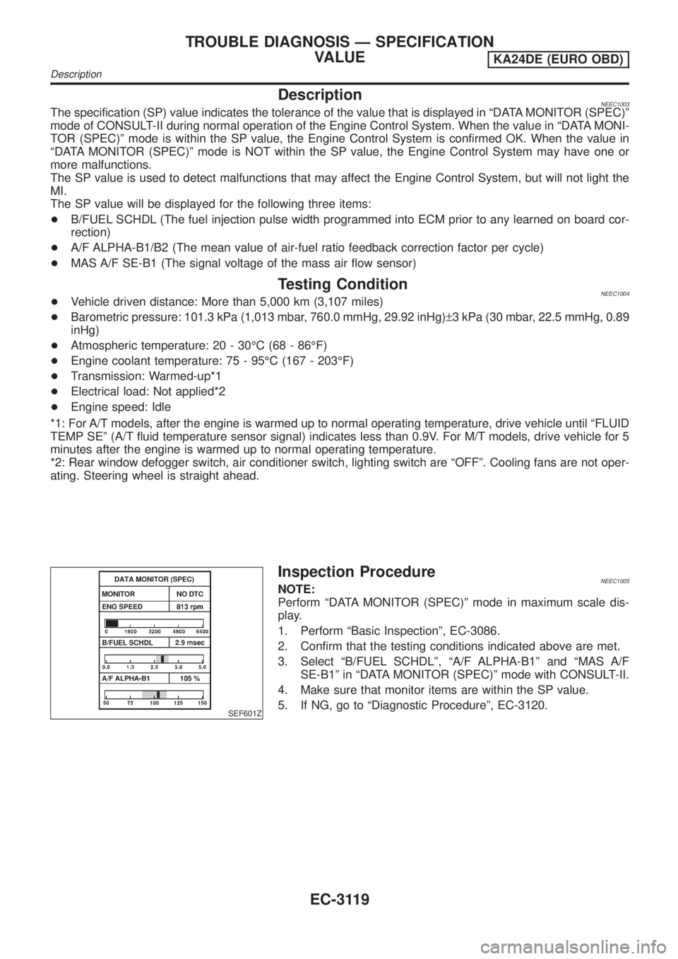
SEF601Z
Inspection ProcedureNEEC1005NOTE:
Perform ªDATA MONITOR (SPEC)º mode in maximum scale dis-
play.
1. Perform ªBasic Inspectionº, EC-3086.
2. Confirm that the testing conditions indicated above are met.
3. Select ªB/FUEL SCHDLº, ªA/F ALPHA-B1º and ªMAS A/F
SE-B1º in ªDATA MONITOR (SPEC)º mode with CONSULT-II.
4. Make sure that monitor items are within the SP value.
5. If NG, go to ªDiagnostic Procedureº, EC-3120.
TROUBLE DIAGNOSIS Ð SPECIFICATION
VALUE
KA24DE (EURO OBD)
Description
EC-3119
Page 158 of 1306
DescriptionNEEC0136SYSTEM DESCRIPTIONNEEC0136S01
Sensor Input Signal to ECMECM func-
tionActuator
Camshaft position sensor Engine speedHeated
oxygen
sensor 1
heater con-
trolHeated oxygen sensor 1 heater
The ECM performs ON/OFF control of the heated oxygen sensor 1 heater corresponding to the engine oper-
ating condition.
OPERATIONNEEC0136S02
Engine speed Heated oxygen sensor 1 heater
Above 3,600 rpm OFF
Below 3,600 rpm ON
CONSULT-II Reference Value in Data Monitor
Mode
NEEC0137Specification data are reference values.
MONITOR ITEM CONDITION SPECIFICATION
HO2S1 HTR (B1)+Engine speed: Below 3,600 rpm ON
+Engine speed: Above 3,600 rpm OFF
ECM Terminals and Reference ValueNEEC0138Specification data are reference values and are measured between each terminal and ground.
CAUTION:
Do not use ECM ground terminals when measuring input/output voltage. Doing so may result in dam-
age to the ECM's transistor. Use a ground other than ECM terminals, such as the ground.
TERMI-
NAL
NO.WIRE
COLORITEM CONDITION DATA (DC Voltage)
119 Y/RHeated oxygen sensor 1
heater[Engine is running]
+Engine speed is below 3,600 rpm.Approximately 0.4V
[Engine is running]
+Engine speed is above 3,600 rpm.BATTERY VOLTAGE
(11 - 14V)
On Board Diagnosis LogicNEEC0139
DTC No.Trouble diag-
nosis nameDTC detecting condition Possible cause
P0031
0031Heated oxy-
gen sensor 1
heater con-
trol circuit
low+The current amperage in the heated oxygen sen-
sor 1 heater circuit is out of the normal range.
(An excessively low voltage signal is sent to
ECM through the heated oxygen sensor 1
heater.)+Harness or connectors
(The heated oxygen sensor 1 heater circuit
is open or shorted.)
+Heated oxygen sensor 1 heater
P0032
0032Heated oxy-
gen sensor 1
heater con-
trol circuit
high+The current amperage in the heated oxygen sen-
sor 1 heater circuit is out of the normal range.
(An excessively high voltage signal is sent to
ECM through the heated oxygen sensor 1
heater.)+Harness or connectors
(The heated oxygen sensor 1 heater circuit
is shorted.)
+Heated oxygen sensor 1 heater
DTC P0031, P0032 HO2S1 HEATERKA24DE (EURO OBD)
Description
EC-3133
Page 161 of 1306

Diagnostic ProcedureNEEC0142
1 CHECK POWER SUPPLY
1. Turn ignition switch OFF.
2. Disconnect heated oxygen sensor 1 harness connector.
SEF331VC
3. Turn ignition switch ON.
4. Check voltage between terminal 3 and ground with CONSULT-II or tester.
SEF732Z
Voltage: Battery voltage
OK or NG
OK©GO TO 3.
NG©GO TO 2.
2 DETECT MALFUNCTIONING PART
Check the following.
+10A fuse
+Harness for open or short between heated oxygen sensor 1 and 10A fuse
©Repair harness or connectors.
3 CHECK OUTPUT SIGNAL CIRCUIT
1. Turn ignition switch OFF.
2. Disconnect ECM harness connector.
3. Check harness continuity between heated oxygen sensor 1 terminal 1 and ECM terminal 119. Refer to the Wiring Dia-
gram.
Continuity should exist.
4. Also check harness for short to ground or short to power.
OK or NG
OK©GO TO 4.
NG©Repair open circuit or short to ground or short to power in harness or connectors.
DTC P0031, P0032 HO2S1 HEATERKA24DE (EURO OBD)
Diagnostic Procedure
EC-3136
Page 162 of 1306

4 CHECK HEATED OXYGEN SENSOR 1 HEATER
Check resistance between terminals 1 and 3.
SEF731Z
Resistance: 2.3 - 4.3Wat 25ÉC (77ÉF)
Check continuity between terminals 1 and 2, 3 and 2.
Continuity should not exist.
CAUTION:
+Discard any heated oxygen sensor which has been dropped from a height of more than 0.5 m (19.7 in) onto a
hard surface such as a concrete floor; use a new one.
+Before installing new oxygen sensor, clean exhaust system threads using Oxygen Sensor Thread Cleaner tool
J-43897-18 or J-43897-12 and approved anti-seize lubricant.
OK or NG
OK©GO TO 5.
NG©Replace heated oxygen sensor 1.
5 CHECK INTERMITTENT INCIDENT
Perform ªTROUBLE DIAGNOSIS FOR INTERMITTENT INCIDENTº, EC-3123.
©INSPECTION END
DTC P0031, P0032 HO2S1 HEATERKA24DE (EURO OBD)
Diagnostic Procedure
EC-3137
Page 163 of 1306
DescriptionNEEC0180SYSTEM DESCRIPTIONNEEC0180S01
Sensor Input Signal to ECMECM func-
tionActuator
Camshaft position sensor Engine speedHeated
oxygen
sensor 2
heater con-
trolHeated oxygen sensor 2 heater
The ECM performs ON/OFF control of the heated oxygen sensor 2 heater corresponding to the engine speed.
OPERATIONNEEC0180S02
Engine speed rpm Heated oxygen sensor 2 heater
Above 4,000 OFF
Below 4,000 ON
CONSULT-II Reference Value in Data Monitor
Mode
NEEC0181Specification data are reference values.
MONITOR ITEM CONDITION SPECIFICATION
HO2S2 HTR (B1)+Engine speed: Below 4,000 rpm [After driving for 2 minutes at a
speed of 70 km/h (43 MPH) or more]ON
+Ignition switch ON (Engine stopped)
+Engine is running above 4,000 rpmOFF
ECM Terminals and Reference ValueNEEC0182Specification data are reference values and are measured between each terminal and ground.
CAUTION:
Do not use ECM ground terminals when measuring input/output voltage. Doing so may result in dam-
age to the ECM's transistor. Use a ground other than ECM terminals, such as the ground.
TERMI-
NAL
NO.WIRE
COLORITEM CONDITION DATA (DC Voltage)
122 G/BHeated oxygen sensor 2
heater[Engine is running]
+After driving for 2 minutes at a speed of 70 km/h
(43 MPH) or moreApproximately 0.4V
[Ignition switch ªONº]
+Engine stoppedBATTERY VOLTAGE
(11 - 14V)
On Board Diagnosis LogicNEEC0183
DTC No.Trouble diag-
nosis nameDTC detecting condition Possible cause
P0037
0037Heated oxy-
gen sensor 2
heater con-
trol circuit
low+The current amperage in the heated oxygen sen-
sor 2 heater circuit is out of the normal range.
(An excessively low voltage signal is sent to
ECM through the heated oxygen sensor 2
heater.)+Harness or connectors
(The heated oxygen sensor 2 heater circuit
is open or shorted.)
+Heated oxygen sensor 2 heater
DTC P0037, P0038 HO2S2 HEATERKA24DE (EURO OBD)
Description
EC-3138
Page 164 of 1306

DTC No.Trouble diag-
nosis nameDTC detecting condition Possible cause
P0038
0038Heated oxy-
gen sensor 2
heater con-
trol circuit
high+The current amperage in the heated oxygen sen-
sor 2 heater circuit is out of the normal range.
(An excessively high voltage signal is sent to
ECM through the heated oxygen sensor 2
heater.)+Harness or connectors
(The heated oxygen sensor 2 heater circuit
is shorted.)
+Heated oxygen sensor 2 heater
DTC Confirmation ProcedureNEEC0184NOTE:
If ªDTC Confirmation Procedureº has been previously conducted,
always turn ignition switch OFF and wait at least 5 seconds before
conducting the next test.
TESTING CONDITION:
Before performing the following procedure, confirm that bat-
tery voltage is in between 10.5V at idle.
SEF175Y
With CONSULT-II
1) Turn ignition switch ON and select ªDATA MONITORº mode
with CONSULT-II.
2) Start engine and drive vehicle at a speed of more than 70 km/h
(43 MPH) for 2 consecutive minutes.
3) If 1st trip DTC is detected, go to ªDiagnostic Procedureº,
EC-3141.
With GST
1) Start engine.
2) Drive vehicle at a speed of more than 70 km/h (43 MPH) for 2
consecutive minutes.
3) Stop vehicle and let engine idle for at least 6 seconds.
4) Turn ignition switch OFF and wait at least 10 seconds.
5) Start engine.
6) Drive vehicle at a speed of more than 70 km/h (43 MPH) for 2
consecutive minutes
7) Stop vehicle and let engine idle for at least 6 seconds.
8) Select ªMODE 3º with GST.
9) If DTC is detected, go to ªDiagnostic Procedureº, EC-3141.
When using GST, ªDTC Confirmation Procedureº should be
performed twice as much as when using CONSULT-II because
GST cannot display MODE 7 (1st trip DTC) concerning this
diagnosis. Therefore, using CONSULT-II is recommended.
DTC P0037, P0038 HO2S2 HEATERKA24DE (EURO OBD)
On Board Diagnosis Logic
EC-3139
Page 166 of 1306
Diagnostic ProcedureNEEC0186
1 CHECK POWER SUPPLY
1. Turn ignition switch OFF.
2. Disconnect heated oxygen sensor 2 harness connector.
3. Turn ignition switch ON.
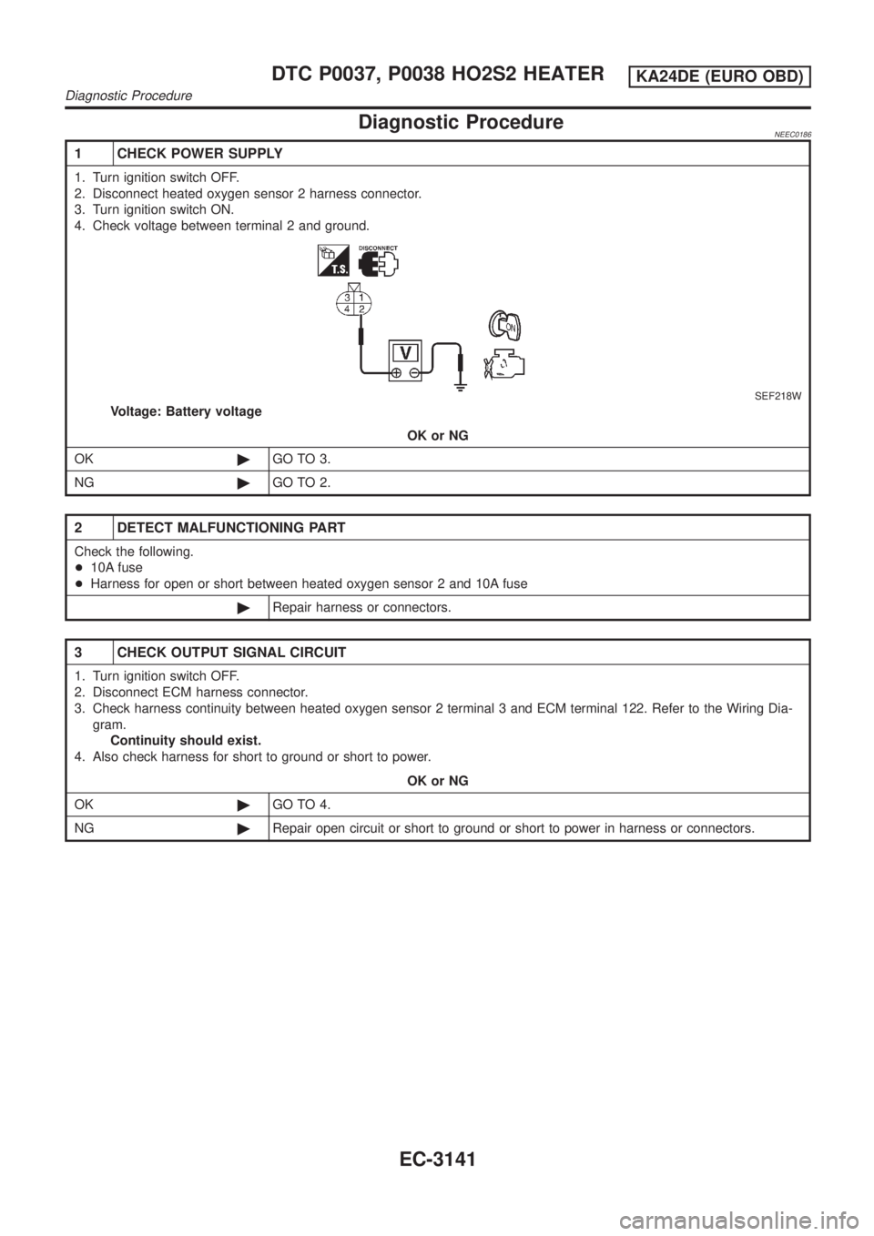
4. Check voltage between terminal 2 and ground.
SEF218W
Voltage: Battery voltage
OK or NG
OK©GO TO 3.
NG©GO TO 2.
2 DETECT MALFUNCTIONING PART
Check the following.
+10A fuse
+Harness for open or short between heated oxygen sensor 2 and 10A fuse
©Repair harness or connectors.
3 CHECK OUTPUT SIGNAL CIRCUIT
1. Turn ignition switch OFF.
2. Disconnect ECM harness connector.
3. Check harness continuity between heated oxygen sensor 2 terminal 3 and ECM terminal 122. Refer to the Wiring Dia-
gram.
Continuity should exist.
4. Also check harness for short to ground or short to power.
OK or NG
OK©GO TO 4.
NG©Repair open circuit or short to ground or short to power in harness or connectors.
DTC P0037, P0038 HO2S2 HEATERKA24DE (EURO OBD)
Diagnostic Procedure
EC-3141
Page 167 of 1306
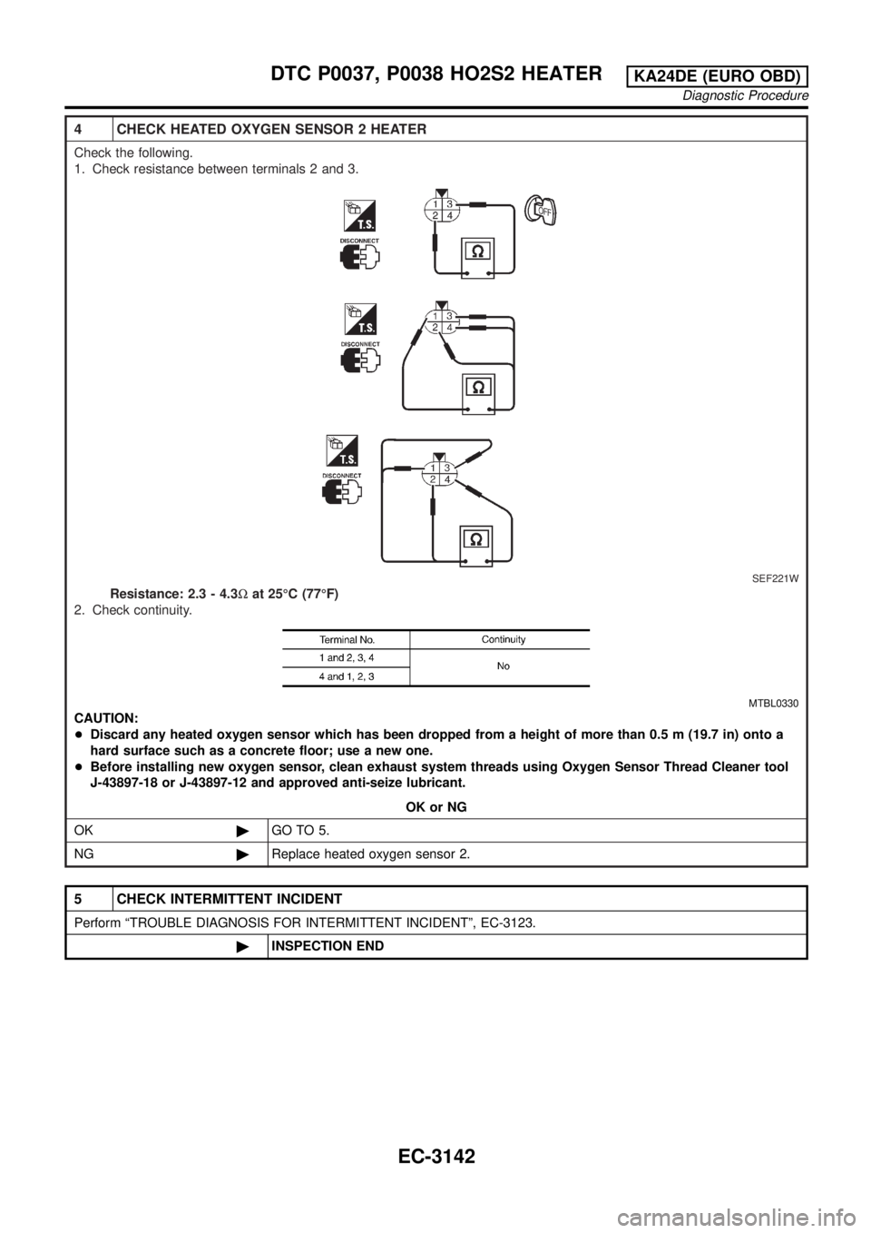
4 CHECK HEATED OXYGEN SENSOR 2 HEATER
Check the following.
1. Check resistance between terminals 2 and 3.
SEF221W
Resistance: 2.3 - 4.3Wat 25ÉC (77ÉF)
2. Check continuity.
MTBL0330
CAUTION:
+Discard any heated oxygen sensor which has been dropped from a height of more than 0.5 m (19.7 in) onto a
hard surface such as a concrete floor; use a new one.
+Before installing new oxygen sensor, clean exhaust system threads using Oxygen Sensor Thread Cleaner tool
J-43897-18 or J-43897-12 and approved anti-seize lubricant.
OK or NG
OK©GO TO 5.
NG©Replace heated oxygen sensor 2.
5 CHECK INTERMITTENT INCIDENT
Perform ªTROUBLE DIAGNOSIS FOR INTERMITTENT INCIDENTº, EC-3123.
©INSPECTION END
DTC P0037, P0038 HO2S2 HEATERKA24DE (EURO OBD)
Diagnostic Procedure
EC-3142