2001 NISSAN PICK-UP sensor
[x] Cancel search: sensorPage 70 of 1306
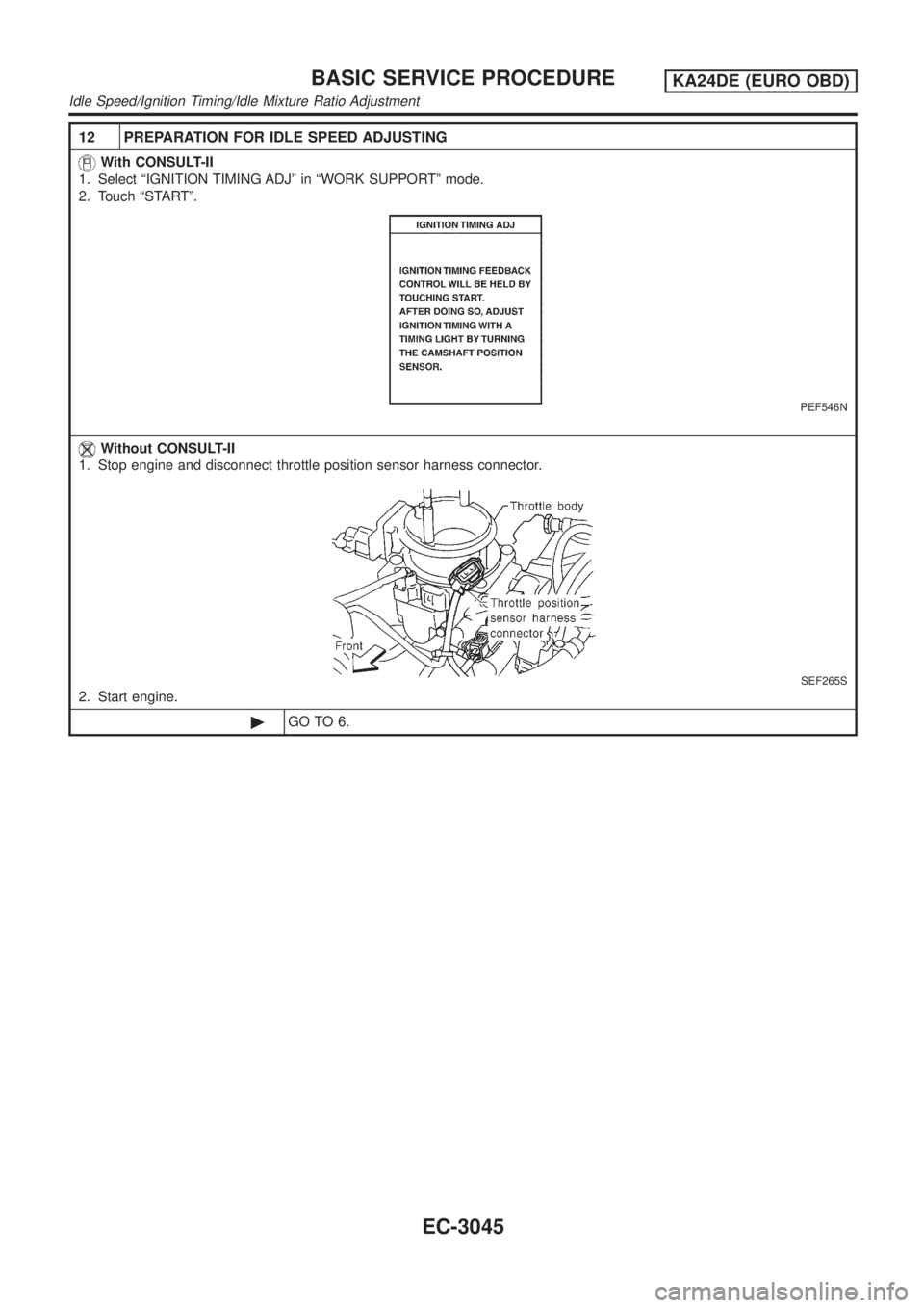
12 PREPARATION FOR IDLE SPEED ADJUSTING
With CONSULT-II
1. Select ªIGNITION TIMING ADJº in ªWORK SUPPORTº mode.
2. Touch ªSTARTº.
PEF546N
Without CONSULT-II
1. Stop engine and disconnect throttle position sensor harness connector.
SEF265S
2. Start engine.
©GO TO 6.
BASIC SERVICE PROCEDUREKA24DE (EURO OBD)
Idle Speed/Ignition Timing/Idle Mixture Ratio Adjustment
EC-3045
Page 71 of 1306
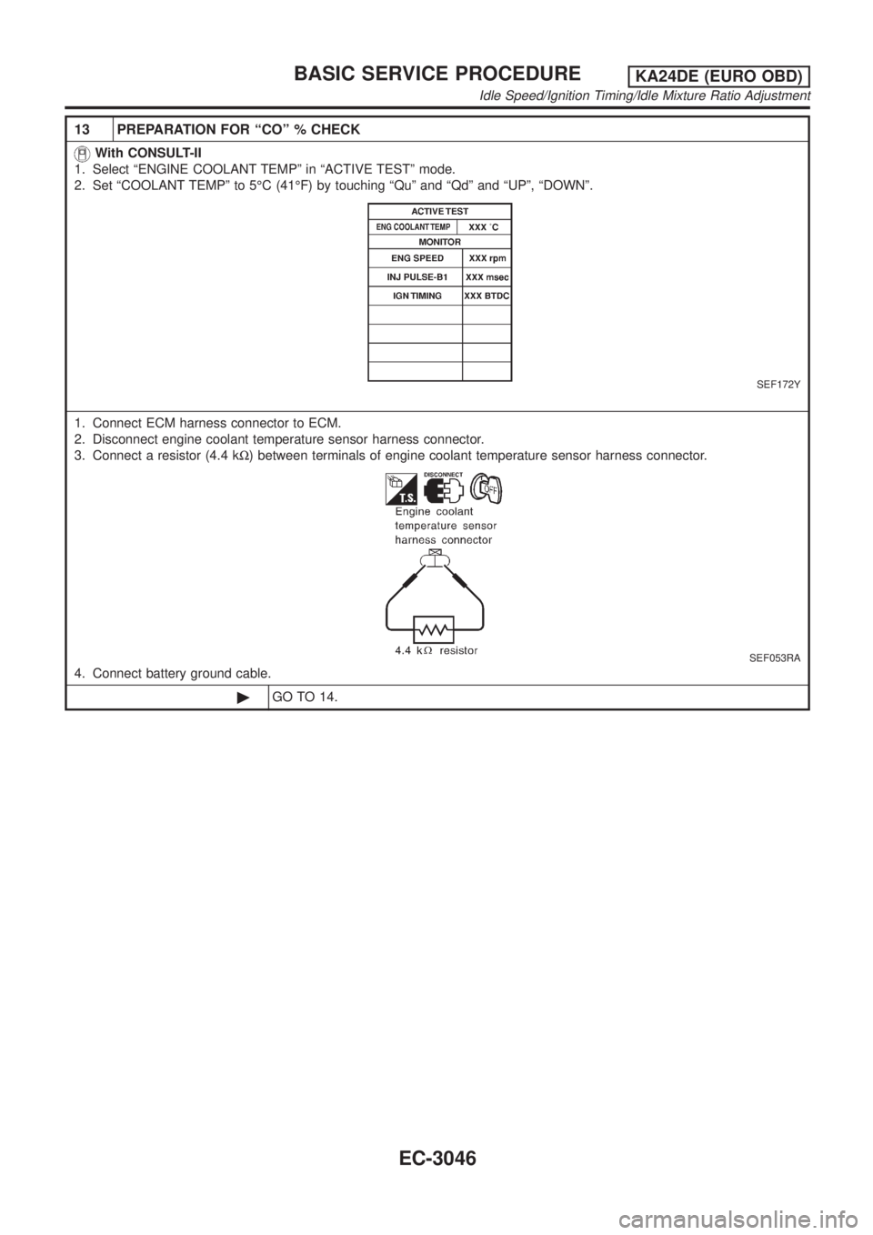
13 PREPARATION FOR ªCOº % CHECK
With CONSULT-II
1. Select ªENGINE COOLANT TEMPº in ªACTIVE TESTº mode.
2. Set ªCOOLANT TEMPº to 5ÉC (41ÉF) by touching ªQuº and ªQdº and ªUPº, ªDOWNº.
SEF172Y
1. Connect ECM harness connector to ECM.
2. Disconnect engine coolant temperature sensor harness connector.
3. Connect a resistor (4.4 kW) between terminals of engine coolant temperature sensor harness connector.
SEF053RA
4. Connect battery ground cable.
©GO TO 14.
BASIC SERVICE PROCEDUREKA24DE (EURO OBD)
Idle Speed/Ignition Timing/Idle Mixture Ratio Adjustment
EC-3046
Page 72 of 1306
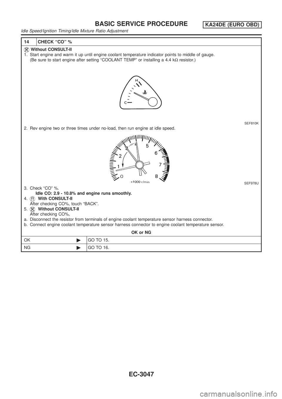
14 CHECK ªCOº %
Without CONSULT-II
1. Start engine and warm it up until engine coolant temperature indicator points to middle of gauge.
(Be sure to start engine after setting ªCOOLANT TEMPº or installing a 4.4 kWresistor.)
SEF810K
2. Rev engine two or three times under no-load, then run engine at idle speed.
SEF978U
3. Check ªCOº %.
Idle CO: 2.9 - 10.8% and engine runs smoothly.
4.
With CONSULT-II
After checking CO%, touch ªBACKº.
5.
Without CONSULT-II
After checking CO%,
a. Disconnect the resistor from terminals of engine coolant temperature sensor harness connector.
b. Connect engine coolant temperature sensor harness connector to engine coolant temperature sensor.
OK or NG
OK©GO TO 15.
NG©GO TO 16.
BASIC SERVICE PROCEDUREKA24DE (EURO OBD)
Idle Speed/Ignition Timing/Idle Mixture Ratio Adjustment
EC-3047
Page 73 of 1306
15 CHECK HEATED OXYGEN SENSOR 1 SIGNAL
With CONSULT-II
1. Replace heated oxygen sensor 1.
2. See ªHO2S1 MNTR (B1)º in ªDATA MONITORº mode.
3. Maintain engine at 2,000 rpm under no-load (engine is warmed up to normal operating temperature.). Check that the
monitor fluctuates between ªLEANº and ªRICHº more than five times during 10 seconds.
1 cycle: RICH®LEAN®RICH
2 cycles: RICH®LEAN®RICH®LEAN®RICH
Without CONSULT-II
1. Stop engine.
2. Replace heated oxygen sensor 1.
3. Start engine and warm it up to normal operating temperature.
4. Run engine at approx. 2,000 rpm for approx. 2 minutes under no-load.
5. Set voltmeter probe between ECM terminal 50 and ground.
6. Make sure that voltage fluctuates between 0 - 0.3V and 0.6 - 1.0V more than 5 times during 10 seconds at 2,000 rpm.
1 time: 0 - 0.3V®0.6 - 1.0V®0 - 0.3V
2 times: 0 - 0.3V®0.6 - 1.0V®0 - 0.3V®0.6 - 1.0V®0 - 0.3V
OK or NG
OK©GO TO 12.
NG©GO TO 16.
16 DETECT MALFUNCTIONING PART
1. Connect heated oxygen sensor 1 harness connector to heated oxygen sensor 1.
2. Check fuel pressure regulator. Refer to EC-3034.
3. Check mass air flow sensor and its circuit.
Refer to EC-3143, EC-3151.
4. Check injector and its circuit.
Refer to EC-3369.
Clean or replace if necessary.
5. Check engine coolant temperature sensor and its circuit. Refer to EC-3165.
6. Check ECM function by substituting another known-good ECM.
(ECM may be the cause of a problem, but this is rarely the case.)
©GO TO 12.
+If a vehicle contains a part which is operating outside of design specifications with no MI
illumination, the part shall not be replaced prior to emission testing unless it is determined that
the part has been tampered with or abused in such a way that the diagnostic system cannot rea-
sonably be expected to detect the resulting malfunction.
BASIC SERVICE PROCEDUREKA24DE (EURO OBD)
Idle Speed/Ignition Timing/Idle Mixture Ratio Adjustment
EC-3048
Page 74 of 1306
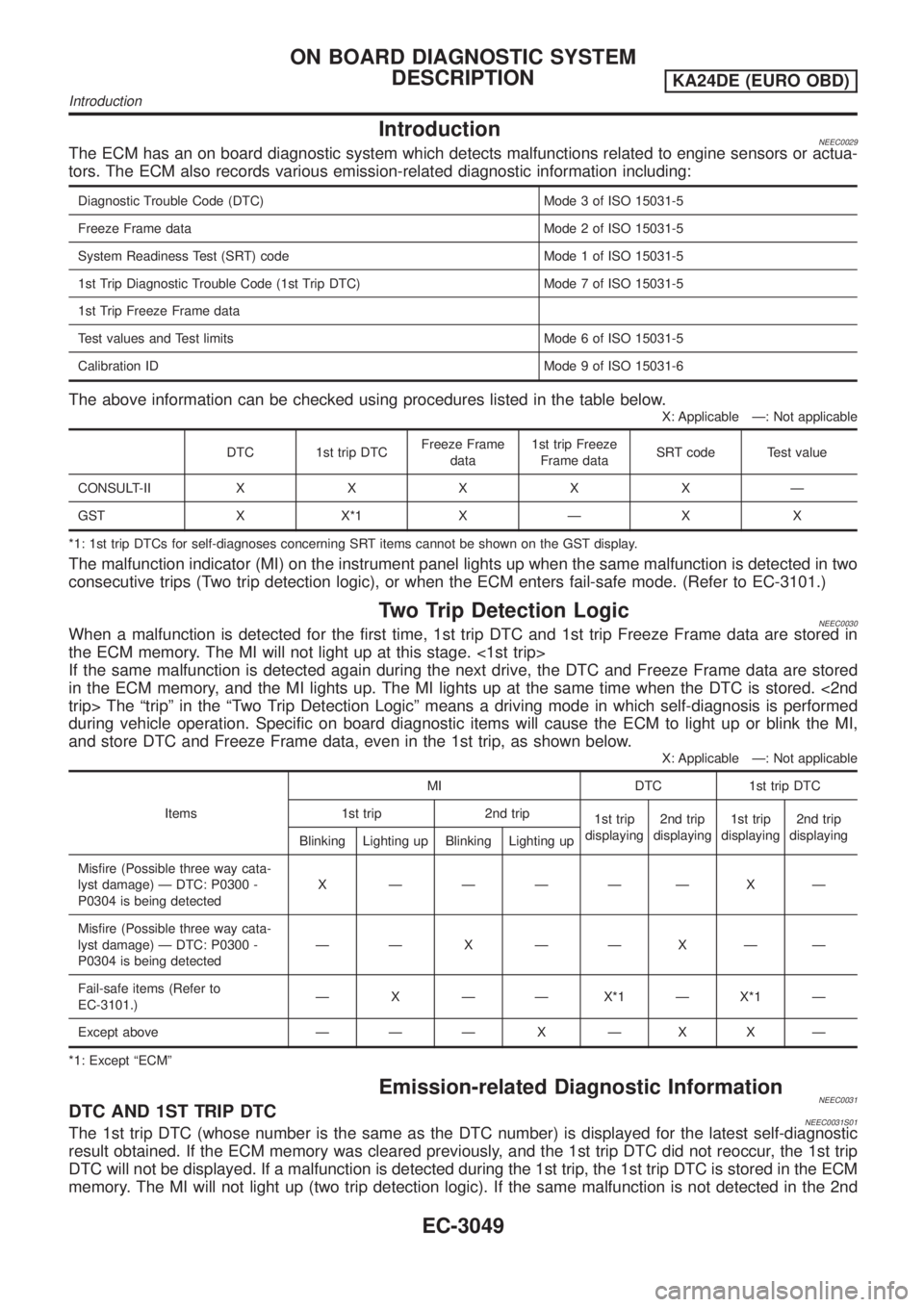
IntroductionNEEC0029The ECM has an on board diagnostic system which detects malfunctions related to engine sensors or actua-
tors. The ECM also records various emission-related diagnostic information including:
Diagnostic Trouble Code (DTC) Mode 3 of ISO 15031-5
Freeze Frame data Mode 2 of ISO 15031-5
System Readiness Test (SRT) code Mode 1 of ISO 15031-5
1st Trip Diagnostic Trouble Code (1st Trip DTC) Mode 7 of ISO 15031-5
1st Trip Freeze Frame data
Test values and Test limits Mode 6 of ISO 15031-5
Calibration ID Mode 9 of ISO 15031-6
The above information can be checked using procedures listed in the table below.
X: Applicable Ð: Not applicable
DTC 1st trip DTCFreeze Frame
data1st trip Freeze
Frame dataSRT code Test value
CONSULT-IIXXXXXÐ
GST X X*1 X Ð X X
*1: 1st trip DTCs for self-diagnoses concerning SRT items cannot be shown on the GST display.
The malfunction indicator (MI) on the instrument panel lights up when the same malfunction is detected in two
consecutive trips (Two trip detection logic), or when the ECM enters fail-safe mode. (Refer to EC-3101.)
Two Trip Detection LogicNEEC0030When a malfunction is detected for the first time, 1st trip DTC and 1st trip Freeze Frame data are stored in
the ECM memory. The MI will not light up at this stage. <1st trip>
If the same malfunction is detected again during the next drive, the DTC and Freeze Frame data are stored
in the ECM memory, and the MI lights up. The MI lights up at the same time when the DTC is stored. <2nd
trip> The ªtripº in the ªTwo Trip Detection Logicº means a driving mode in which self-diagnosis is performed
during vehicle operation. Specific on board diagnostic items will cause the ECM to light up or blink the MI,
and store DTC and Freeze Frame data, even in the 1st trip, as shown below.
X: Applicable Ð: Not applicable
ItemsMI DTC 1st trip DTC
1st trip 2nd trip
1st trip
displaying2nd trip
displaying1st trip
displaying2nd trip
displaying
Blinking Lighting up Blinking Lighting up
Misfire (Possible three way cata-
lyst damage) Ð DTC: P0300 -
P0304 is being detectedX ÐÐÐÐÐXÐ
Misfire (Possible three way cata-
lyst damage) Ð DTC: P0300 -
P0304 is being detectedÐÐ X ÐÐXÐÐ
Fail-safe items (Refer to
EC-3101.)Ð X Ð Ð X*1 Ð X*1 Ð
Except above Ð Ð Ð X Ð X X Ð
*1: Except ªECMº
Emission-related Diagnostic InformationNEEC0031DTC AND 1ST TRIP DTCNEEC0031S01The 1st trip DTC (whose number is the same as the DTC number) is displayed for the latest self-diagnostic
result obtained. If the ECM memory was cleared previously, and the 1st trip DTC did not reoccur, the 1st trip
DTC will not be displayed. If a malfunction is detected during the 1st trip, the 1st trip DTC is stored in the ECM
memory. The MI will not light up (two trip detection logic). If the same malfunction is not detected in the 2nd
ON BOARD DIAGNOSTIC SYSTEM
DESCRIPTION
KA24DE (EURO OBD)
Introduction
EC-3049
Page 77 of 1306
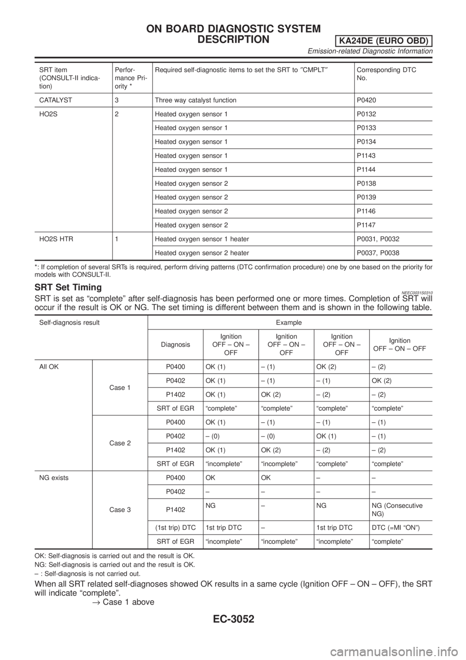
SRT item
(CONSULT-II indica-
tion)Perfor-
mance Pri-
ority *Required self-diagnostic items to set the SRT to²CMPLT²Corresponding DTC
No.
CATALYST 3 Three way catalyst function P0420
HO2S 2 Heated oxygen sensor 1 P0132
Heated oxygen sensor 1 P0133
Heated oxygen sensor 1 P0134
Heated oxygen sensor 1 P1143
Heated oxygen sensor 1 P1144
Heated oxygen sensor 2 P0138
Heated oxygen sensor 2 P0139
Heated oxygen sensor 2 P1146
Heated oxygen sensor 2 P1147
HO2S HTR 1 Heated oxygen sensor 1 heater P0031, P0032
Heated oxygen sensor 2 heater P0037, P0038
*: If completion of several SRTs is required, perform driving patterns (DTC confirmation procedure) one by one based on the priority for
models with CONSULT-II.
SRT Set TimingNEEC0031S0310SRT is set as ªcompleteº after self-diagnosis has been performed one or more times. Completion of SRT will
occur if the result is OK or NG. The set timing is different between them and is shown in the following table.
Self-diagnosis result Example
DiagnosisIgnition
OFF±ON±
OFFIgnition
OFF±ON±
OFFIgnition
OFF±ON±
OFFIgnition
OFF±ON±OFF
All OK
Case 1P0400 OK (1) ± (1) OK (2) ± (2)
P0402 OK (1) ± (1) ± (1) OK (2)
P1402 OK (1) OK (2) ± (2) ± (2)
SRT of EGR ªcompleteº ªcompleteº ªcompleteº ªcompleteº
Case 2P0400 OK (1) ± (1) ± (1) ± (1)
P0402 ± (0) ± (0) OK (1) ± (1)
P1402 OK (1) OK (2) ± (2) ± (2)
SRT of EGR ªincompleteº ªincompleteº ªcompleteº ªcompleteº
NG exists
Case 3P0400 OK OK ± ±
P0402±±±±
P1402NG ± NG NG (Consecutive
NG)
(1st trip) DTC 1st trip DTC ± 1st trip DTC DTC (=MI ªONº)
SRT of EGR ªincompleteº ªincompleteº ªincompleteº ªcompleteº
OK: Self-diagnosis is carried out and the result is OK.
NG: Self-diagnosis is carried out and the result is OK.
± : Self-diagnosis is not carried out.
When all SRT related self-diagnoses showed OK results in a same cycle (Ignition OFF ± ON ± OFF), the SRT
will indicate ªcompleteº.
®Case 1 above
ON BOARD DIAGNOSTIC SYSTEM
DESCRIPTION
KA24DE (EURO OBD)
Emission-related Diagnostic Information
EC-3052
Page 83 of 1306
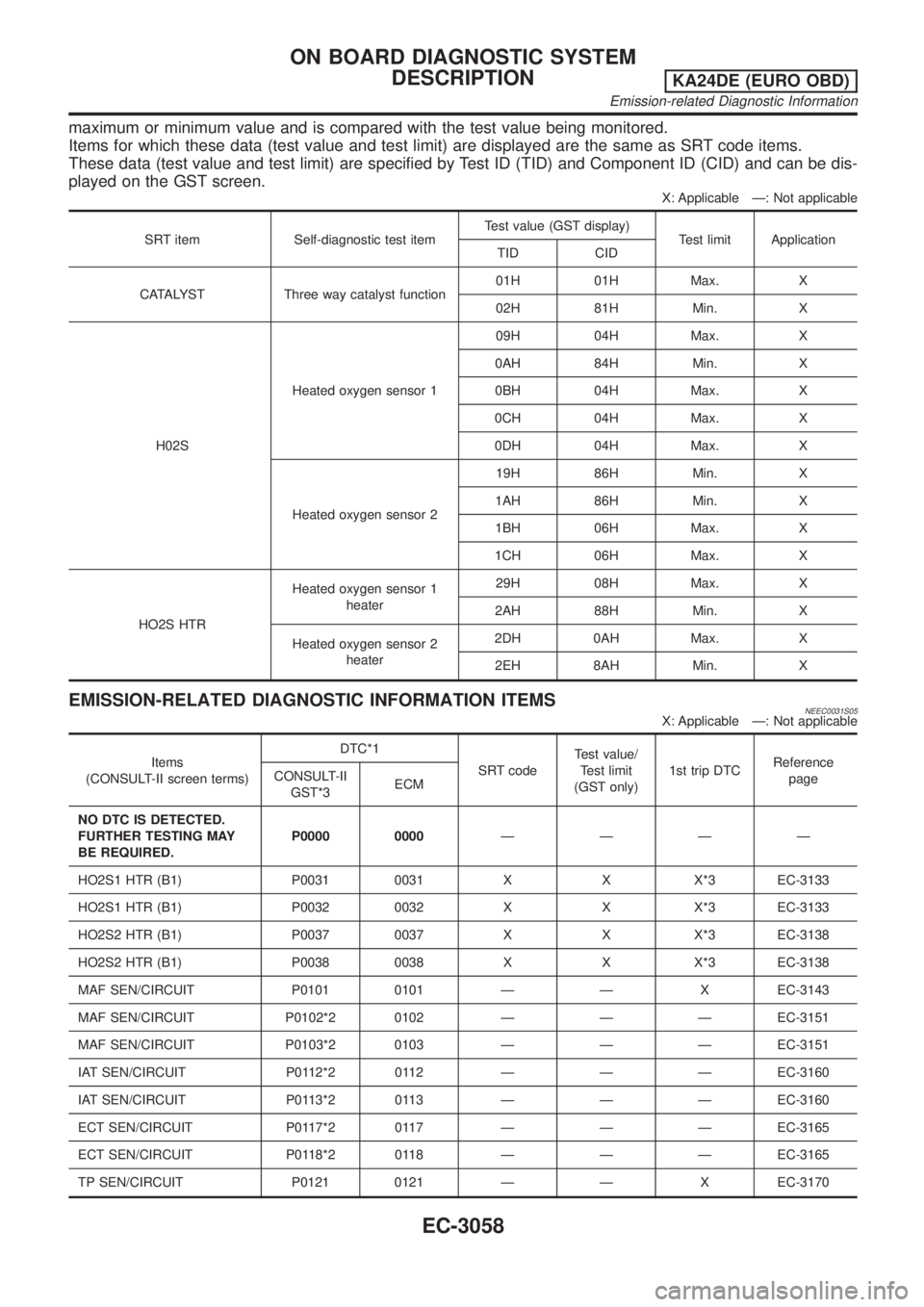
maximum or minimum value and is compared with the test value being monitored.
Items for which these data (test value and test limit) are displayed are the same as SRT code items.
These data (test value and test limit) are specified by Test ID (TID) and Component ID (CID) and can be dis-
played on the GST screen.
X: Applicable Ð: Not applicable
SRT item Self-diagnostic test itemTest value (GST display)
Test limit Application
TID CID
CATALYST Three way catalyst function01H 01H Max. X
02H 81H Min. X
H02SHeated oxygen sensor 109H 04H Max. X
0AH 84H Min. X
0BH 04H Max. X
0CH 04H Max. X
0DH 04H Max. X
Heated oxygen sensor 219H 86H Min. X
1AH 86H Min. X
1BH 06H Max. X
1CH 06H Max. X
HO2S HTRHeated oxygen sensor 1
heater29H 08H Max. X
2AH 88H Min. X
Heated oxygen sensor 2
heater2DH 0AH Max. X
2EH 8AH Min. X
EMISSION-RELATED DIAGNOSTIC INFORMATION ITEMSNEEC0031S05X: Applicable Ð: Not applicable
Items
(CONSULT-II screen terms)DTC*1
SRT codeTest value/
Test limit
(GST only)1st trip DTCReference
page CONSULT-II
GST*3ECM
NO DTC IS DETECTED.
FURTHER TESTING MAY
BE REQUIRED.P0000 0000ÐÐÐÐ
HO2S1 HTR (B1) P0031 0031 X X X*3 EC-3133
HO2S1 HTR (B1) P0032 0032 X X X*3 EC-3133
HO2S2 HTR (B1) P0037 0037 X X X*3 EC-3138
HO2S2 HTR (B1) P0038 0038 X X X*3 EC-3138
MAF SEN/CIRCUIT P0101 0101 Ð Ð X EC-3143
MAF SEN/CIRCUIT P0102*2 0102 Ð Ð Ð EC-3151
MAF SEN/CIRCUIT P0103*2 0103 Ð Ð Ð EC-3151
IAT SEN/CIRCUIT P0112*2 0112 Ð Ð Ð EC-3160
IAT SEN/CIRCUIT P0113*2 0113 Ð Ð Ð EC-3160
ECT SEN/CIRCUIT P0117*2 0117 Ð Ð Ð EC-3165
ECT SEN/CIRCUIT P0118*2 0118 Ð Ð Ð EC-3165
TP SEN/CIRCUIT P0121 0121 Ð Ð X EC-3170
ON BOARD DIAGNOSTIC SYSTEM
DESCRIPTION
KA24DE (EURO OBD)
Emission-related Diagnostic Information
EC-3058
Page 84 of 1306
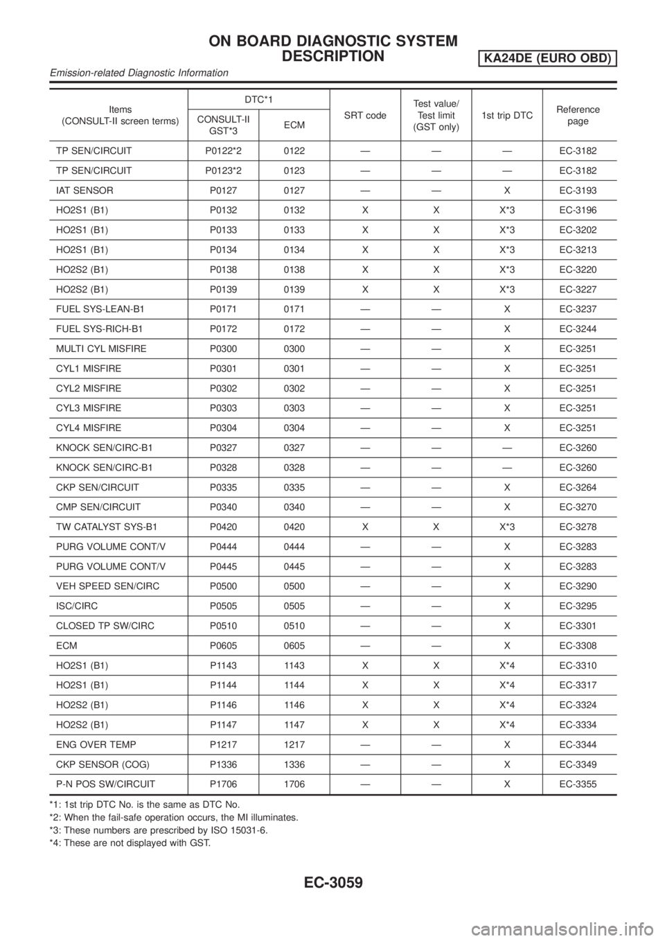
Items
(CONSULT-II screen terms)DTC*1
SRT codeTest value/
Test limit
(GST only)1st trip DTCReference
page CONSULT-II
GST*3ECM
TP SEN/CIRCUIT P0122*2 0122 Ð Ð Ð EC-3182
TP SEN/CIRCUIT P0123*2 0123 Ð Ð Ð EC-3182
IAT SENSOR P0127 0127 Ð Ð X EC-3193
HO2S1 (B1) P0132 0132 X X X*3 EC-3196
HO2S1 (B1) P0133 0133 X X X*3 EC-3202
HO2S1 (B1) P0134 0134 X X X*3 EC-3213
HO2S2 (B1) P0138 0138 X X X*3 EC-3220
HO2S2 (B1) P0139 0139 X X X*3 EC-3227
FUEL SYS-LEAN-B1 P0171 0171 Ð Ð X EC-3237
FUEL SYS-RICH-B1 P0172 0172 Ð Ð X EC-3244
MULTI CYL MISFIRE P0300 0300 Ð Ð X EC-3251
CYL1 MISFIRE P0301 0301 Ð Ð X EC-3251
CYL2 MISFIRE P0302 0302 Ð Ð X EC-3251
CYL3 MISFIRE P0303 0303 Ð Ð X EC-3251
CYL4 MISFIRE P0304 0304 Ð Ð X EC-3251
KNOCK SEN/CIRC-B1 P0327 0327 Ð Ð Ð EC-3260
KNOCK SEN/CIRC-B1 P0328 0328 Ð Ð Ð EC-3260
CKP SEN/CIRCUIT P0335 0335 Ð Ð X EC-3264
CMP SEN/CIRCUIT P0340 0340 Ð Ð X EC-3270
TW CATALYST SYS-B1 P0420 0420 X X X*3 EC-3278
PURG VOLUME CONT/V P0444 0444 Ð Ð X EC-3283
PURG VOLUME CONT/V P0445 0445 Ð Ð X EC-3283
VEH SPEED SEN/CIRC P0500 0500 Ð Ð X EC-3290
ISC/CIRC P0505 0505 Ð Ð X EC-3295
CLOSED TP SW/CIRC P0510 0510 Ð Ð X EC-3301
ECM P0605 0605 Ð Ð X EC-3308
HO2S1 (B1) P1143 1143 X X X*4 EC-3310
HO2S1 (B1) P1144 1144 X X X*4 EC-3317
HO2S2 (B1) P1146 1146 X X X*4 EC-3324
HO2S2 (B1) P1147 1147 X X X*4 EC-3334
ENG OVER TEMP P1217 1217 Ð Ð X EC-3344
CKP SENSOR (COG) P1336 1336 Ð Ð X EC-3349
P-N POS SW/CIRCUIT P1706 1706 Ð Ð X EC-3355
*1: 1st trip DTC No. is the same as DTC No.
*2: When the fail-safe operation occurs, the MI illuminates.
*3: These numbers are prescribed by ISO 15031-6.
*4: These are not displayed with GST.
ON BOARD DIAGNOSTIC SYSTEM
DESCRIPTION
KA24DE (EURO OBD)
Emission-related Diagnostic Information
EC-3059