Page 365 of 1306
4 DETECT MALFUNCTIONING PART
Check the following.
+Harness for open or short between ECM and heated oxygen sensor 2
©Repair open circuit or short to ground or short to power in harness or connectors.
5 CHECK GROUND CIRCUIT
1. Check harness continuity between heated oxygen sensor 2 terminal 4 and engine ground. Refer to Wiring Diagram.
Continuity should exist.
2. Also check harness for short to power.
OK or NG
OK (With CONSULT-II)©GO TO 7.
OK (Without CONSULT-
II)©GO TO 8.
NG©GO TO 6.
6 DETECT MALFUNCTIONING PART
Check the following.
+Joint connector-3
+Harness for open or short between heated oxygen sensor 2 and engine ground
©Repair open circuit or short to power in harness or connectors.
DTC P1147 HO2S2KA24DE (EURO OBD)
Diagnostic Procedure
EC-3340
Page 366 of 1306

7 CHECK HEATED OXYGEN SENSOR 2
With CONSULT-II
1. Reconnect all harness connectors disconnected.
2. Start engine and drive vehicle at a speed of more than 70 km/h (43 MPH) for 2 consecutive minutes.
3. Stop vehicle with engine running.
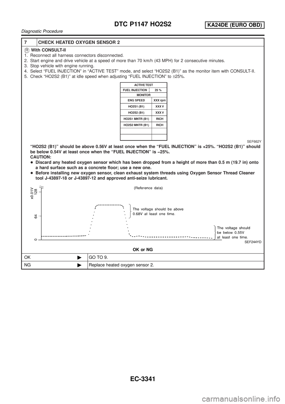
4. Select ªFUEL INJECTIONº in ªACTIVE TESTº mode, and select ªHO2S2 (B1)º as the monitor item with CONSULT-II.
5. Check ªHO2S2 (B1)º at idle speed when adjusting ªFUEL INJECTIONº to±25%.
SEF662Y
ªHO2S2 (B1)º should be above 0.56V at least once when the ªFUEL INJECTIONº is +25%. ªHO2S2 (B1)º should
be below 0.54V at least once when the ªFUEL INJECTIONº is þ25%.
CAUTION:
+Discard any heated oxygen sensor which has been dropped from a height of more than 0.5 m (19.7 in) onto
a hard surface such as a concrete floor; use a new one.
+Before installing new oxygen sensor, clean exhaust system threads using Oxygen Sensor Thread Cleaner
tool J-43897-18 or J-43897-12 and approved anti-seize lubricant.
SEF244YD
OK or NG
OK©GO TO 9.
NG©Replace heated oxygen sensor 2.
DTC P1147 HO2S2KA24DE (EURO OBD)
Diagnostic Procedure
EC-3341
Page 367 of 1306

8 CHECK HEATED OXYGEN SENSOR 2
Without CONSULT-II
1. Reconnect all harness connectors disconnected.
2. Start engine and drive vehicle at a speed of more than 70 km/h (43 MPH) for 2 consecutive minutes.
3. Stop vehicle with engine running.
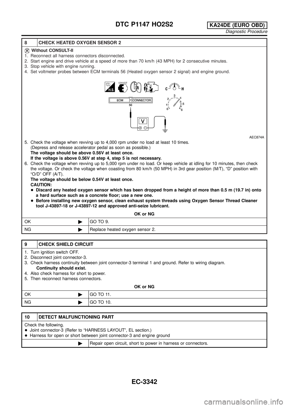
4. Set voltmeter probes between ECM terminals 56 (Heated oxygen sensor 2 signal) and engine ground.
AEC874A
5. Check the voltage when revving up to 4,000 rpm under no load at least 10 times.
(Depress and release accelerator pedal as soon as possible.)
The voltage should be above 0.56V at least once.
If the voltage is above 0.56V at step 4, step 5 is not necessary.
6. Check the voltage when revving up to 5,000 rpm under no load. Or keep vehicle at idling for 10 minutes, then check
the voltage. Or check the voltage when coasting from 80 km/h (50 MPH) in 3rd gear position (M/T), ªDº position with
ªO/Dº OFF (A/T).
The voltage should be below 0.54V at least once.
CAUTION:
+Discard any heated oxygen sensor which has been dropped from a height of more than 0.5 m (19.7 in) onto
a hard surface such as a concrete floor; use a new one.
+Before installing new oxygen sensor, clean exhaust system threads using Oxygen Sensor Thread Cleaner
tool J-43897-18 or J-43897-12 and approved anti-seize lubricant.
OK or NG
OK©GO TO 9.
NG©Replace heated oxygen sensor 2.
9 CHECK SHIELD CIRCUIT
1. Turn ignition switch OFF.
2. Disconnect joint connector-3.
3. Check harness continuity between joint connector-3 terminal 1 and ground. Refer to wiring diagram.
Continuity should exist.
4. Also check harness for short to power.
5. Then reconnect harness connectors.
OK or NG
OK©GO TO 11.
NG©GO TO 10.
10 DETECT MALFUNCTIONING PART
Check the following.
+Joint connector-3 (Refer to ªHARNESS LAYOUTº, EL section.)
+Harness for open or short between joint connector-3 and engine ground
©Repair open circuit, short to power in harness or connectors.
DTC P1147 HO2S2KA24DE (EURO OBD)
Diagnostic Procedure
EC-3342
Page 369 of 1306

On Board Diagnosis LogicNEEC1534If the cooling fan or another component in the cooling system malfunctions, engine coolant temperature will
rise.
When the engine coolant temperature reaches an abnormally high temperature condition, a malfunction is
indicated.
DTC No. Malfunction is detected when ...Check Items
(Possible Cause)
P1217
1217+Engine coolant temperature reaches an abnormally high
temperature.+Cooling fan (crankshaft driven)
Radiator hose
+Radiator
+Radiator cap
+Water pump
+Thermostat
+Engine coolant temperature sensor
For more information, refer to ªMAIN 11 CAUSES
OF OVERHEATINGº, EC-3348.
CAUTION:
When a malfunction is indicated, be sure to replace the coolant. Refer to MA section, ªChanging Engine
Coolantº. Also, replace the engine oil.
1) Fill radiator with coolant up to specified level with a filling speed of 2 liters per minute. Be sure
to use coolant with the proper mixture ratio. Refer to MA section, ªAnti-freeze Coolant Mixture
Ratioº.
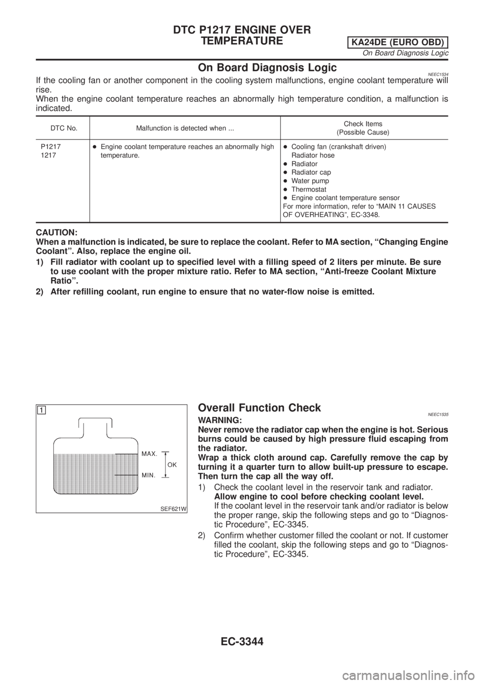
2) After refilling coolant, run engine to ensure that no water-flow noise is emitted.
SEF621W
Overall Function CheckNEEC1535WARNING:
Never remove the radiator cap when the engine is hot. Serious
burns could be caused by high pressure fluid escaping from
the radiator.
Wrap a thick cloth around cap. Carefully remove the cap by
turning it a quarter turn to allow built-up pressure to escape.
Then turn the cap all the way off.
1) Check the coolant level in the reservoir tank and radiator.
Allow engine to cool before checking coolant level.
If the coolant level in the reservoir tank and/or radiator is below
the proper range, skip the following steps and go to ªDiagnos-
tic Procedureº, EC-3345.
2) Confirm whether customer filled the coolant or not. If customer
filled the coolant, skip the following steps and go to ªDiagnos-
tic Procedureº, EC-3345.
DTC P1217 ENGINE OVER
TEMPERATURE
KA24DE (EURO OBD)
On Board Diagnosis Logic
EC-3344
Page 370 of 1306
Diagnostic ProcedureNEEC1536
1 CHECK COOLING SYSTEM FOR LEAK
Apply pressure to the cooling system with a tester, and check if the pressure drops.
Testing pressure: 157 kPa (1.57 bar, 1.6 kg/cm2, 23 psi)
CAUTION:
Higher than the specified pressure may cause radiator damage.
SLC754A
Pressure should not drop.
OK or NG
OK©GO TO 2.
NG©Check the following for leak.
+Hose
+Radiator
+Water pump
Refer to LC section, ªWater Pumpº.
2 CHECK RADIATOR CAP
Apply pressure to cap with a tester.
SLC755A
Radiator cap relief pressure:
78 - 98 kPa (0.78 - 0.98 bar, 0.8 - 1.0 kg/cm2, 11 - 14 psi)
OK or NG
OK©GO TO 3.
NG©Replace radiator cap.
DTC P1217 ENGINE OVER
TEMPERATURE
KA24DE (EURO OBD)
Diagnostic Procedure
EC-3345
Page 371 of 1306
3 CHECK THERMOSTAT
1. Check valve seating condition at normal room temperatures.
It should seat tightly.
2. Check valve opening temperature and valve lift.
SLC343
Valve opening temperature:
76.5ÉC (170ÉF) [standard]
Valve lift:
More than 8 mm/90ÉC (0.31 in/194ÉF)
3. Check if valve is closed at 5ÉC (9ÉF) below valve opening temperature.
For details, refer to LC section, ªThermostatº.
OK or NG
OK©GO TO 4.
NG©Replace thermostat.
DTC P1217 ENGINE OVER
TEMPERATURE
KA24DE (EURO OBD)
Diagnostic Procedure
EC-3346
Page 372 of 1306
4 CHECK ENGINE COOLANT TEMPERATURE SENSOR
Check resistance as shown in the figure.
SEF152P
MTBL0285
SEF012P
OK or NG
OK©GO TO 5.
NG©Replace engine coolant temperature sensor.
5 CHECK MAIN 11 CAUSES
If the cause cannot be isolated, go to ªMAIN 11 CAUSES OF OVERHEATINGº, EC-3348.
©INSPECTION END
Perform FINAL CHECK by the following procedure after repair
is completed.
1. Warm up engine. Run the vehicle for at least 20 minutes. Pay
attention to engine coolant temperature gauge on the instru-
ment panel. If the reading shows an abnormally high
temperature, another part may be malfunctioning.
2. Stop vehicle and let engine idle. Check the intake and exhaust
systems for leaks by listening for noise or visually inspecting
the components.
3. Allow engine to cool and visually check for oil and coolant
leaks. Then, perform ªOVERALL FUNCTION CHECKº.
DTC P1217 ENGINE OVER
TEMPERATURE
KA24DE (EURO OBD)
Diagnostic Procedure
EC-3347
Page 373 of 1306

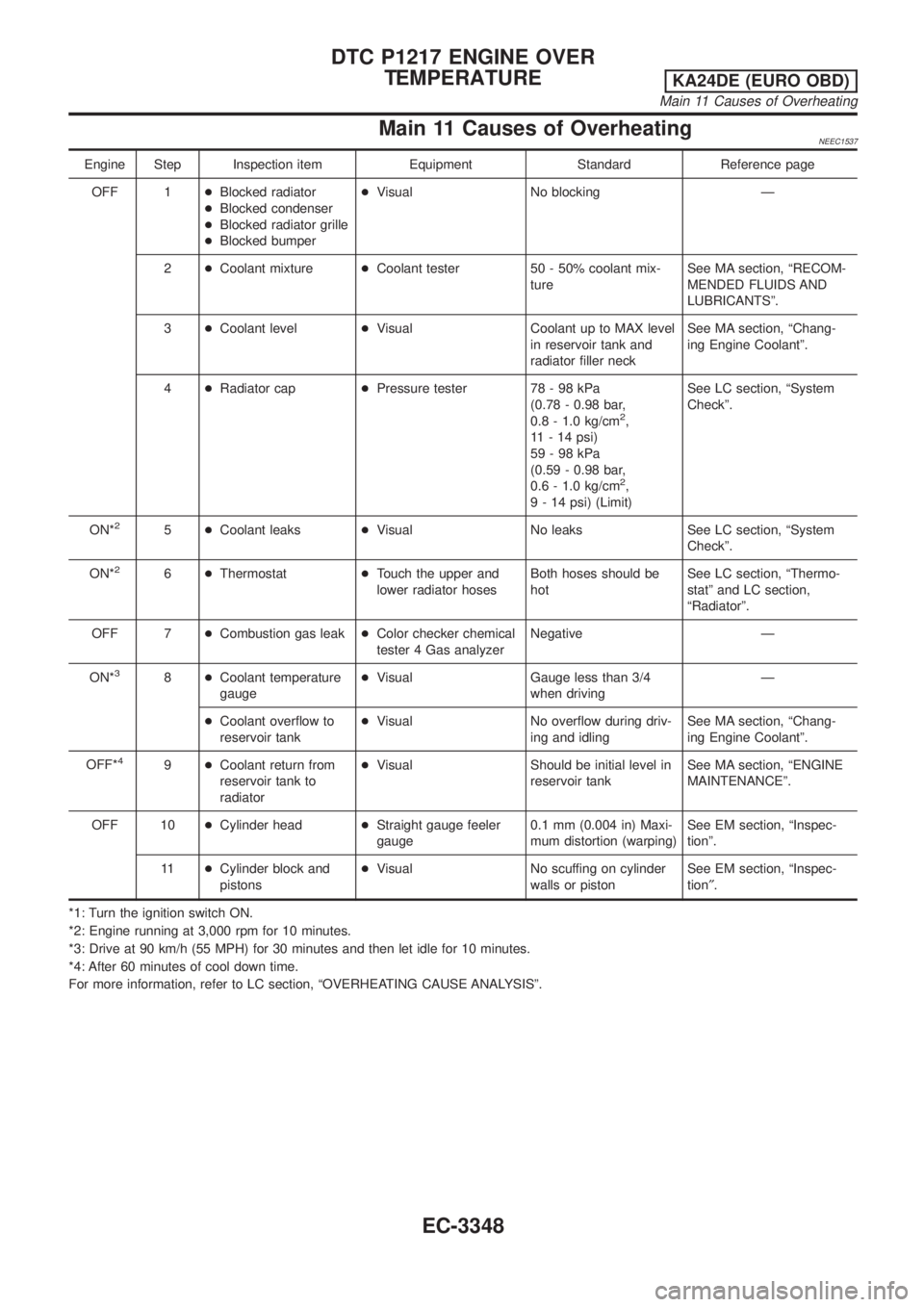
Main 11 Causes of OverheatingNEEC1537
Engine Step Inspection item Equipment Standard Reference page
OFF 1+Blocked radiator
+Blocked condenser
+Blocked radiator grille
+Blocked bumper+Visual No blocking Ð
2+Coolant mixture+Coolant tester 50 - 50% coolant mix-
tureSee MA section, ªRECOM-
MENDED FLUIDS AND
LUBRICANTSº.
3+Coolant level+Visual Coolant up to MAX level
in reservoir tank and
radiator filler neckSee MA section, ªChang-
ing Engine Coolantº.
4+Radiator cap+Pressure tester 78 - 98 kPa
(0.78 - 0.98 bar,
0.8 - 1.0 kg/cm
2,
11 - 14 psi)
59-98kPa
(0.59 - 0.98 bar,
0.6 - 1.0 kg/cm
2,
9 - 14 psi) (Limit)See LC section, ªSystem
Checkº.
ON*
25+Coolant leaks+Visual No leaks See LC section, ªSystem
Checkº.
ON*
26+Thermostat+Touch the upper and
lower radiator hosesBoth hoses should be
hotSee LC section, ªThermo-
statº and LC section,
ªRadiatorº.
OFF 7+Combustion gas leak+Color checker chemical
tester 4 Gas analyzerNegative Ð
ON*
38+Coolant temperature
gauge+Visual Gauge less than 3/4
when drivingÐ
+Coolant overflow to
reservoir tank+Visual No overflow during driv-
ing and idlingSee MA section, ªChang-
ing Engine Coolantº.
OFF*
49+Coolant return from
reservoir tank to
radiator+Visual Should be initial level in
reservoir tankSee MA section, ªENGINE
MAINTENANCEº.
OFF 10+Cylinder head+Straight gauge feeler
gauge0.1 mm (0.004 in) Maxi-
mum distortion (warping)See EM section, ªInspec-
tionº.
11+Cylinder block and
pistons+Visual No scuffing on cylinder
walls or pistonSee EM section, ªInspec-
tion².
*1: Turn the ignition switch ON.
*2: Engine running at 3,000 rpm for 10 minutes.
*3: Drive at 90 km/h (55 MPH) for 30 minutes and then let idle for 10 minutes.
*4: After 60 minutes of cool down time.
For more information, refer to LC section, ªOVERHEATING CAUSE ANALYSISº.
DTC P1217 ENGINE OVER
TEMPERATURE
KA24DE (EURO OBD)
Main 11 Causes of Overheating
EC-3348