Page 397 of 1306
2 CHECK POWER SUPPLY
1. Stop engine.
2. Disconnect injector harness connector.
3. Turn ignition switch ON.
4. Check voltage between injector terminal 2 and ground with CONSULT-II or tester.
SEC277D
Voltage: Battery voltage
OK or NG
OK©GO TO 4.
NG©GO TO 3.
3 DETECT MALFUNCTIONING PART
Check the following.
+10A fuse
+Harness for open or short between injector and fuse
©Repair harness or connectors.
4 CHECK OUTPUT SIGNAL CIRCUIT
1. Turn ignition switch OFF.
2. Disconnect ECM harness connector.
3. Check harness continuity between injector terminal 1 and ECM terminals 102, 104, 109, 111. Refer to Wiring Diagram.
Continuity should exist.
4. Also check harness for short to ground and short to power.
OK or NG
OK©GO TO 6.
NG©GO TO 5.
5 DETECT MALFUNCTIONING PART
Check the harness for open or short between ECM and injector.
©Repair open circuit or short to ground or short to power in harness or connectors.
INJECTORKA24DE (EURO OBD)
Diagnostic Procedure
EC-3372
Page 412 of 1306
Diagnostic Procedure=NEEC0454
1 INSPECTION START
Do you have CONSULT-II?
YesorNo
Ye s©GO TO 2.
No©GO TO 3.
2 CHECK OVERALL FUNCTION
With CONSULT-II
1. Start engine.
2. Check ªPW/ST SIGNALº in ªDATA MONITORº mode with CONSULT-II under the following conditions.
LEC065A
OK or NG
OK©INSPECTION END
NG©GO TO 4.
3 CHECK OVERALL FUNCTION
Without CONSULT-II
1. Start engine.
2. Check voltage between ECM terminal 39 and ground under the following conditions.
SEF662P
MTBL0142
OK or NG
OK©INSPECTION END
NG©GO TO 4.
POWER STEERING OIL PRESSURE
SWITCH
KA24DE (EURO OBD)
Diagnostic Procedure
EC-3387
Page 413 of 1306

4 CHECK INPUT SIGNAL CIRCUIT
1. Turn ignition switch ªOFFº.
2. Disconnect ECM harness connector.
3. Check harness continuity between ECM terminal 39 and terminal 1. Refer to wiring diagram.
Continuity should exist.
4. Also check harness for short to ground and short to power.
OK or NG
OK©GO TO 6.
NG©GO TO 5.
5 DETECT MALFUNCTIONING PART
Check the following.
+Harness connectors M5, E101
Check the harness for open or short between ECM and power steering oil pressure switch.
©Repair open circuit or short to ground or short to power in harness or connectors.
6 CHECK GROUND CIRCUIT
1. Disconnect power steering oil pressure switch harness connector.
2. Check continuity between power steering oil pressure switch harness connector terminal 2 and ground.
Continuity should exist.
OK or NG
OK©
NG©Repair open circuit or short to power in harness or connectors.
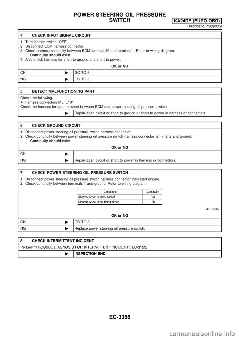
7 CHECK POWER STEERING OIL PRESSURE SWITCH
1. Disconnect power steering oil pressure switch harness connector then start engine.
2. Check continuity between terminals 1 and ground. Refer to wiring diagram.
MTBL0307
OK or NG
OK©GO TO 8.
NG©Replace power steering oil pressure switch.
8 CHECK INTERMITTENT INCIDENT
Perform ªTROUBLE DIAGNOSIS FOR INTERMITTENT INCIDENTº, EC-3123.
©INSPECTION END
POWER STEERING OIL PRESSURE
SWITCH
KA24DE (EURO OBD)
Diagnostic Procedure
EC-3388
Page 417 of 1306
Diagnostic Procedure=NEEC0464
1 CHECK OVERALL FUNCTION
1. Start engine and warm it up to normal operating temperature.
2. Check idle speed.
700±50 rpm
If NG, adjust idle speed.
3. Push air conditioner switch ON and turn fan switch to 4-speed.
4. Recheck idle speed.
MEF634E
850 rpm or more
OK or NG
OK©INSPECTION END
NG©GO TO 2.
2 CHECK AIR CONDITIONER FUNCTION
Check if air conditioner compressor functions normally.
OK or NG
OK©GO TO 3.
NG©Refer to ªSymptom Tableº in ªTROUBLE DIAGNOSISº, HA section.
IACV-FICD SOLENOID VALVEKA24DE (EURO OBD)
Diagnostic Procedure
EC-3392
Page 418 of 1306
3 CHECK POWER SUPPLY
1. Stop engine.
2. Disconnect IACV-FICD solenoid valve harness connector.
SEF342V
3. Start engine, then push A/C switch ON and turn fan switch to 4-speed.
4. Check voltage between terminal 1 and ground with CONSULT-II or tester.
SEC281D
Voltage: Battery voltage
OK or NG
OK©GO TO 5.
NG©GO TO 4.
4 DETECT MALFUNCTIONING PART
Check the following.
+Harness connectors E101, M5
+Harness for open or short between IACV-FICD solenoid valve and air conditioner relay
©Repair open circuit, short to ground or short to power in harness or connectors.
IACV-FICD SOLENOID VALVEKA24DE (EURO OBD)
Diagnostic Procedure
EC-3393
Page 428 of 1306
tion due to receiving external noise, degraded operation
of ICs, etc.
+Keep engine control system parts and harnesses dry.
+Before replacing ECM, perform Terminals and Reference
Value inspection and make sure ECM functions properly.
Refer to EC-3464.
+Fuel filter switch is equipped except for Europe.
If MIL illuminates or blinks irregularly when engine is
running, water may have accumulated in fuel filter. Drain
water from fuel filter. Refer to EC-3427. If this does not
correct the problem, perform specified trouble diagnos-
tic procedures.
+After performing each TROUBLE DIAGNOSIS, perform
ªDTC Confirmation Procedureº or ªOverall Function
Checkº.
The DTC should not be displayed in the ª DTC Confirma-
tion Procedureº if the repair is completed. The ªOverall
Function Checkº should be a good result if the repair is
completed.
MEF040D
SAT652J
PRECAUTIONSYD25DDTi
Precautions (Cont'd)
EC-3403
Page 439 of 1306
Crankcase Ventilation System
DESCRIPTION
In this system, blow-by gas is sucked into the air inlet pipe after
oil separation by oil separator in the rocker cover.
INSPECTION
Ventilation hose
1. Check hoses and hose connections for leaks.
2. Disconnect all hoses and clean with compressed air. If any
hose cannot be freed of obstructions, replace.
SEC240D
SEC692
ENGINE AND EMISSION BASIC CONTROL SYSTEM
DESCRIPTIONYD25DDTi
EC-3414
Page 444 of 1306
Spray Pattern Test
1. Check spray pattern by pumping tester handle one full stroke
per second.
NG spray pattern:
Does not inject straight and strong (B in the fig-
ure).
Fuel drips (C in the figure).
Does not inject evenly (D in the figure).
2. If the spray pattern is not correct, replace injection nozzle
assembly.
Electronic Control Fuel Injection Pump
REMOVAL AND INSTALLATION
Removal
1. Remove the parts shown below.
+Engine hood
+Engine coolant (drain)
+Engine cover
+Heater pipe under intake manifold
+Injection tubes
+Right splash cover (with undercover)
+Right front wheel
SEF434Z
JEC336D
BASIC SERVICE PROCEDUREYD25DDTi
Injection Tube and Injection Nozzle (Cont'd)
EC-3419