2001 NISSAN PICK-UP air condition
[x] Cancel search: air conditionPage 1057 of 1306
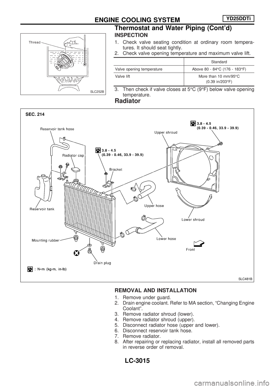
INSPECTION
1. Check valve seating condition at ordinary room tempera-
tures. It should seat tightly.
2. Check valve opening temperature and maximum valve lift.
Standard
Valve opening temperature Above 80 - 84ÉC (176 - 183ÉF)
Valve lift More than 10 mm/95ÉC
(0.39 in/203ÉF)
3. Then check if valve closes at 5ÉC (9ÉF) below valve opening
temperature.
Radiator
REMOVAL AND INSTALLATION
1. Remove under guard.
2. Drain engine coolant. Refer to MA section, ªChanging Engine
Coolantº.
3. Remove radiator shroud (lower).
4. Remove radiator shroud (upper).
5. Disconnect radiator hose (upper and lower).
6. Disconnect reservoir tank hose.
7. Remove radiator.
8. After repairing or replacing radiator, install all removed parts
in reverse order of removal.
SLC252B
SLC481B
ENGINE COOLING SYSTEMYD25DDTi
Thermostat and Water Piping (Cont'd)
LC-3015
Page 1062 of 1306
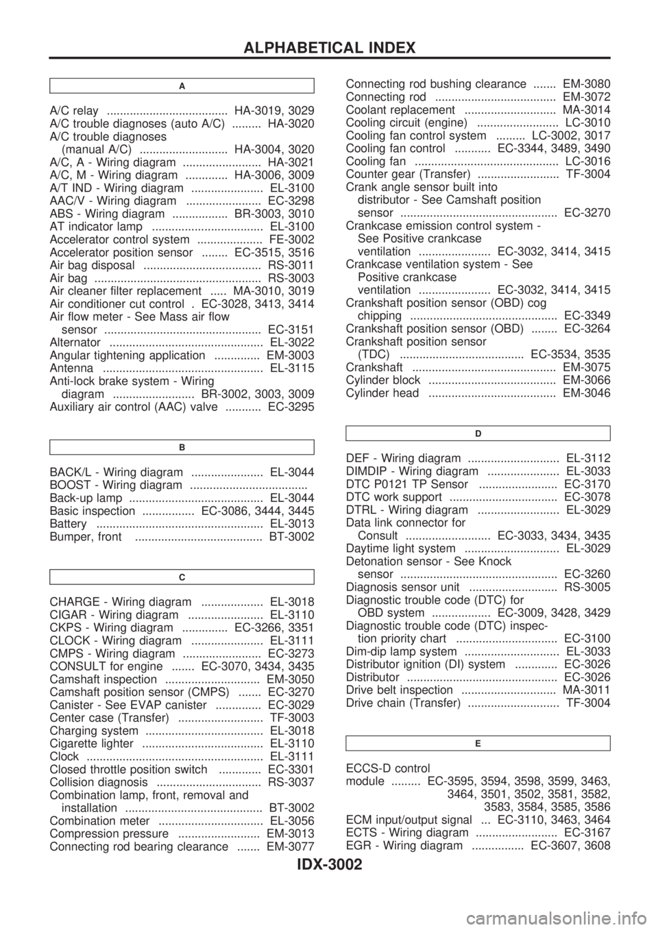
A
A/C relay ..................................... HA-3019, 3029
A/C trouble diagnoses (auto A/C) ......... HA-3020
A/C trouble diagnoses
(manual A/C) ........................... HA-3004, 3020
A/C, A - Wiring diagram ........................ HA-3021
A/C, M - Wiring diagram ............. HA-3006, 3009
A/T IND - Wiring diagram ...................... EL-3100
AAC/V - Wiring diagram ....................... EC-3298
ABS - Wiring diagram ................. BR-3003, 3010
AT indicator lamp .................................. EL-3100
Accelerator control system .................... FE-3002
Accelerator position sensor ........ EC-3515, 3516
Air bag disposal .................................... RS-3011
Air bag ................................................... RS-3003
Air cleaner filter replacement ..... MA-3010, 3019
Air conditioner cut control . EC-3028, 3413, 3414
Air flow meter - See Mass air flow
sensor ................................................ EC-3151
Alternator ............................................... EL-3022
Angular tightening application .............. EM-3003
Antenna ................................................. EL-3115
Anti-lock brake system - Wiring
diagram ......................... BR-3002, 3003, 3009
Auxiliary air control (AAC) valve ........... EC-3295
B
BACK/L - Wiring diagram ...................... EL-3044
BOOST - Wiring diagram ....................................
Back-up lamp ......................................... EL-3044
Basic inspection ................ EC-3086, 3444, 3445
Battery ................................................... EL-3013
Bumper, front ....................................... BT-3002
C
CHARGE - Wiring diagram ................... EL-3018
CIGAR - Wiring diagram ....................... EL-3110
CKPS - Wiring diagram .............. EC-3266, 3351
CLOCK - Wiring diagram ...................... EL-3111
CMPS - Wiring diagram ........................ EC-3273
CONSULT for engine ....... EC-3070, 3434, 3435
Camshaft inspection ............................. EM-3050
Camshaft position sensor (CMPS) ....... EC-3270
Canister - See EVAP canister .............. EC-3029
Center case (Transfer) .......................... TF-3003
Charging system .................................... EL-3018
Cigarette lighter ..................................... EL-3110
Clock ...................................................... EL-3111
Closed throttle position switch ............. EC-3301
Collision diagnosis ................................ RS-3037
Combination lamp, front, removal and
installation .......................................... BT-3002
Combination meter ................................ EL-3056
Compression pressure ......................... EM-3013
Connecting rod bearing clearance ....... EM-3077Connecting rod bushing clearance ....... EM-3080
Connecting rod ..................................... EM-3072
Coolant replacement ............................ MA-3014
Cooling circuit (engine) ......................... LC-3010
Cooling fan control system ......... LC-3002, 3017
Cooling fan control ........... EC-3344, 3489, 3490
Cooling fan ............................................ LC-3016
Counter gear (Transfer) ......................... TF-3004
Crank angle sensor built into
distributor - See Camshaft position
sensor ................................................ EC-3270
Crankcase emission control system -
See Positive crankcase
ventilation ...................... EC-3032, 3414, 3415
Crankcase ventilation system - See
Positive crankcase
ventilation ...................... EC-3032, 3414, 3415
Crankshaft position sensor (OBD) cog
chipping ............................................. EC-3349
Crankshaft position sensor (OBD) ........ EC-3264
Crankshaft position sensor
(TDC) ...................................... EC-3534, 3535
Crankshaft ............................................ EM-3075
Cylinder block ....................................... EM-3066
Cylinder head ....................................... EM-3046
D
DEF - Wiring diagram ............................ EL-3112
DIMDIP - Wiring diagram ...................... EL-3033
DTC P0121 TP Sensor ........................ EC-3170
DTC work support ................................. EC-3078
DTRL - Wiring diagram ......................... EL-3029
Data link connector for
Consult .......................... EC-3033, 3434, 3435
Daytime light system ............................. EL-3029
Detonation sensor - See Knock
sensor ................................................ EC-3260
Diagnosis sensor unit ........................... RS-3005
Diagnostic trouble code (DTC) for
OBD system .................. EC-3009, 3428, 3429
Diagnostic trouble code (DTC) inspec-
tion priority chart ............................... EC-3100
Dim-dip lamp system ............................. EL-3033
Distributor ignition (DI) system ............. EC-3026
Distributor .............................................. EC-3026
Drive belt inspection ............................. MA-3011
Drive chain (Transfer) ............................ TF-3004
E
ECCS-D control
module ......... EC-3595, 3594, 3598, 3599, 3463,
3464, 3501, 3502, 3581, 3582,
3583, 3584, 3585, 3586
ECM input/output signal ... EC-3110, 3463, 3464
ECTS - Wiring diagram ......................... EC-3167
EGR - Wiring diagram ................ EC-3607, 3608
ALPHABETICAL INDEX
IDX-3002
Page 1087 of 1306
![NISSAN PICK-UP 2001 Repair Manual HOW TO ERASE SELF-DIAGNOSIS RESULTS
With CONSULT-II
+ªSELF-DIAG [CURRENT]º
A current Self-diagnosis result is displayed on the CONSULT-II screen in real time. After the malfunc-
tion is repaired com NISSAN PICK-UP 2001 Repair Manual HOW TO ERASE SELF-DIAGNOSIS RESULTS
With CONSULT-II
+ªSELF-DIAG [CURRENT]º
A current Self-diagnosis result is displayed on the CONSULT-II screen in real time. After the malfunc-
tion is repaired com](/manual-img/5/57372/w960_57372-1086.png)
HOW TO ERASE SELF-DIAGNOSIS RESULTS
With CONSULT-II
+ªSELF-DIAG [CURRENT]º
A current Self-diagnosis result is displayed on the CONSULT-II screen in real time. After the malfunc-
tion is repaired completely, no malfunction is detected on ªSELF-DIAG [CURRENT]º.
+ªSELF-DIAG [PAST]º
Return to the ªSELF-DIAG [CURRENT]º CONSULT-II screen
by pushing ªBACKº key of CONSULT-II and select ªSELF-
DIAG [CURRENT]º in ªSELECT DIAG MODEº. Touch
ªERASEº in ªSELF-DIAG [CURRENT]º mode.
NOTE:
If the memory of the malfunction in ªSELF-DIAG [PAST]º is
not erased, the User mode shows the system malfunction by
the operation of the warning lamp even if the malfunction is
repaired completely.
+ªTROUBLE DIAG RECORDº
The memory of ªTROUBLE DIAG RECORDº cannot be erased.
Without CONSULT-II
After a malfunction is repaired, return Diagnosis mode to User mode by switching the ignition ªOFFº for at
least 1 second, then back ªONº. At that time, the self-diagnostic result is cleared.
How to Perform Trouble Diagnoses for Quick
and Accurate Repair
A good understanding of the malfunction conditions can make troubleshooting faster and more accurate.
In general, each customer feels differently about a malfunction. It is important to fully understand the symp-
toms or conditions for a customer complaint.
INFORMATION FROM CUSTOMER
WHAT ........ Vehicle model
WHEN ....... Date, Frequencies
WHERE ..... Road conditions
HOW .......... Operating conditions, Symptoms
PRELIMINARY CHECK
Check that the following parts are in good order.
+Battery [Refer to EL section (ªBATTERYº) of Service Manual.]
+Fuse [Refer to EL section (ªFuseº, ªPOWER SUPPLY ROUTINGº) of Service Manual.]
+System component-to-harness connections
SRS701
TROUBLE DIAGNOSES Ð Supplemental Restraint System (SRS)
Trouble Diagnoses Introduction (Cont'd)
RS-3016
Page 1091 of 1306
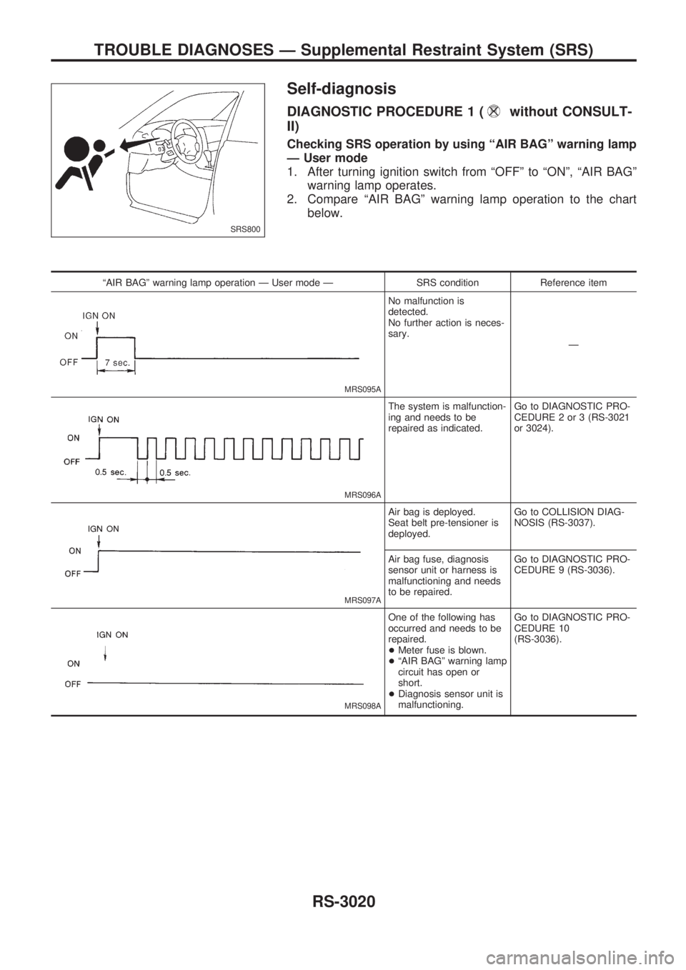
Self-diagnosis
DIAGNOSTIC PROCEDURE 1 (without CONSULT-
II)
Checking SRS operation by using ªAIR BAGº warning lamp
Ð User mode
1. After turning ignition switch from ªOFFº to ªONº, ªAIR BAGº
warning lamp operates.
2. Compare ªAIR BAGº warning lamp operation to the chart
below.
ªAIR BAGº warning lamp operation Ð User mode Ð SRS condition Reference item
MRS095A
No malfunction is
detected.
No further action is neces-
sary.
Ð
MRS096A
The system is malfunction-
ing and needs to be
repaired as indicated.Go to DIAGNOSTIC PRO-
CEDURE 2 or 3 (RS-3021
or 3024).
MRS097A
Air bag is deployed.
Seat belt pre-tensioner is
deployed.Go to COLLISION DIAG-
NOSIS (RS-3037).
Air bag fuse, diagnosis
sensor unit or harness is
malfunctioning and needs
to be repaired.Go to DIAGNOSTIC PRO-
CEDURE 9 (RS-3036).
MRS098A
One of the following has
occurred and needs to be
repaired.
+Meter fuse is blown.
+ªAIR BAGº warning lamp
circuit has open or
short.
+Diagnosis sensor unit is
malfunctioning.Go to DIAGNOSTIC PRO-
CEDURE 10
(RS-3036).
SRS800
TROUBLE DIAGNOSES Ð Supplemental Restraint System (SRS)
RS-3020
Page 1095 of 1306
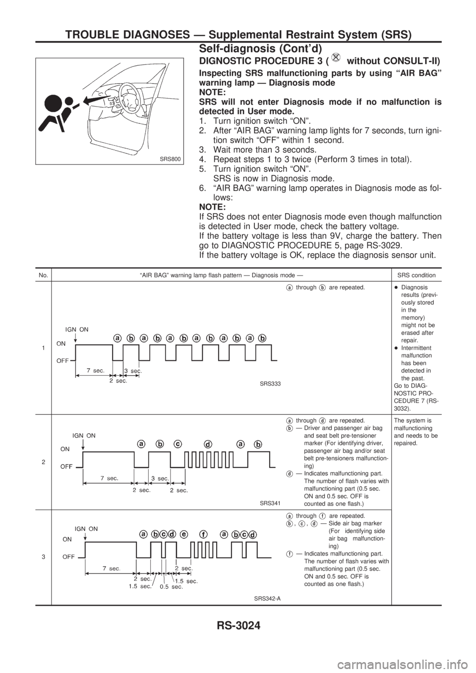
DIGNOSTIC PROCEDURE 3 (without CONSULT-II)
Inspecting SRS malfunctioning parts by using ªAIR BAGº
warning lamp Ð Diagnosis mode
NOTE:
SRS will not enter Diagnosis mode if no malfunction is
detected in User mode.
1. Turn ignition switch ªONº.
2. After ªAIR BAGº warning lamp lights for 7 seconds, turn igni-
tion switch ªOFFº within 1 second.
3. Wait more than 3 seconds.
4. Repeat steps 1 to 3 twice (Perform 3 times in total).
5. Turn ignition switch ªONº.
SRS is now in Diagnosis mode.
6. ªAIR BAGº warning lamp operates in Diagnosis mode as fol-
lows:
NOTE:
If SRS does not enter Diagnosis mode even though malfunction
is detected in User mode, check the battery voltage.
If the battery voltage is less than 9V, charge the battery. Then
go to DIAGNOSTIC PROCEDURE 5, page RS-3029.
If the battery voltage is OK, replace the diagnosis sensor unit.
No. ªAIR BAGº warning lamp flash pattern Ð Diagnosis mode Ð SRS condition
1
SRS333
VathroughVbare repeated.+Diagnosis
results (previ-
ously stored
in the
memory)
might not be
erased after
repair.
+Intermittent
malfunction
has been
detected in
the past.
Go to DIAG-
NOSTIC PRO-
CEDURE 7 (RS-
3032).
2
SRS341
VathroughVdare repeated.
VbÐ Driver and passenger air bag
and seat belt pre-tensioner
marker (For identifying driver,
passenger air bag and/or seat
belt pre-tensioners malfunction-
ing)
VdÐ Indicates malfunctioning part.
The number of flash varies with
malfunctioning part (0.5 sec.
ON and 0.5 sec. OFF is
counted as one flash.)The system is
malfunctioning
and needs to be
repaired.
3
SRS342-A
VathroughVfare repeated.
Vb,Vc,VdÐ Side air bag marker
(For identifying side
air bag malfunction-
ing)
VfÐ Indicates malfunctioning part.
The number of flash varies with
malfunctioning part (0.5 sec.
ON and 0.5 sec. OFF is
counted as one flash.)
SRS800
TROUBLE DIAGNOSES Ð Supplemental Restraint System (SRS)
Self-diagnosis (Cont'd)
RS-3024
Page 1101 of 1306
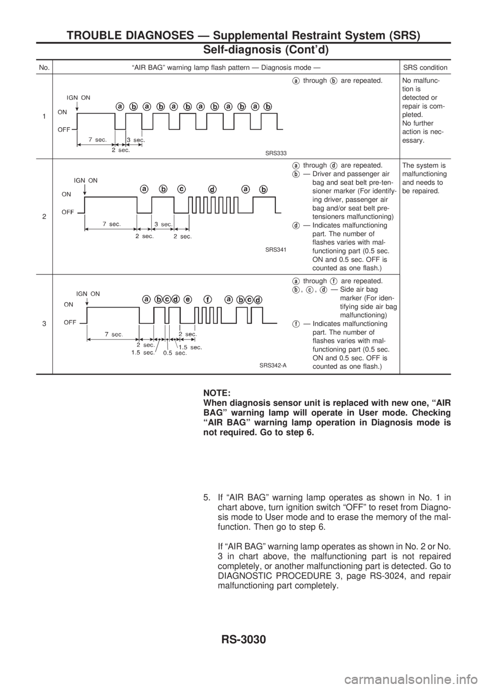
No. ªAIR BAGº warning lamp flash pattern Ð Diagnosis mode Ð SRS condition
1
SRS333
VathroughVbare repeated. No malfunc-
tion is
detected or
repair is com-
pleted.
No further
action is nec-
essary.
2
SRS341
VathroughVdare repeated.
VbÐ Driver and passenger air
bag and seat belt pre-ten-
sioner marker (For identify-
ing driver, passenger air
bag and/or seat belt pre-
tensioners malfunctioning)
VdÐ Indicates malfunctioning
part. The number of
flashes varies with mal-
functioning part (0.5 sec.
ON and 0.5 sec. OFF is
counted as one flash.)The system is
malfunctioning
and needs to
be repaired.
3
SRS342-A
VathroughVfare repeated.
Vb,Vc,VdÐ Side air bag
marker (For iden-
tifying side air bag
malfunctioning)
VfÐ Indicates malfunctioning
part. The number of
flashes varies with mal-
functioning part (0.5 sec.
ON and 0.5 sec. OFF is
counted as one flash.)
NOTE:
When diagnosis sensor unit is replaced with new one, ªAIR
BAGº warning lamp will operate in User mode. Checking
ªAIR BAGº warning lamp operation in Diagnosis mode is
not required. Go to step 6.
5. If ªAIR BAGº warning lamp operates as shown in No. 1 in
chart above, turn ignition switch ªOFFº to reset from Diagno-
sis mode to User mode and to erase the memory of the mal-
function. Then go to step 6.
If ªAIR BAGº warning lamp operates as shown in No. 2 or No.
3 in chart above, the malfunctioning part is not repaired
completely, or another malfunctioning part is detected. Go to
DIAGNOSTIC PROCEDURE 3, page RS-3024, and repair
malfunctioning part completely.
TROUBLE DIAGNOSES Ð Supplemental Restraint System (SRS)
Self-diagnosis (Cont'd)
RS-3030
Page 1102 of 1306
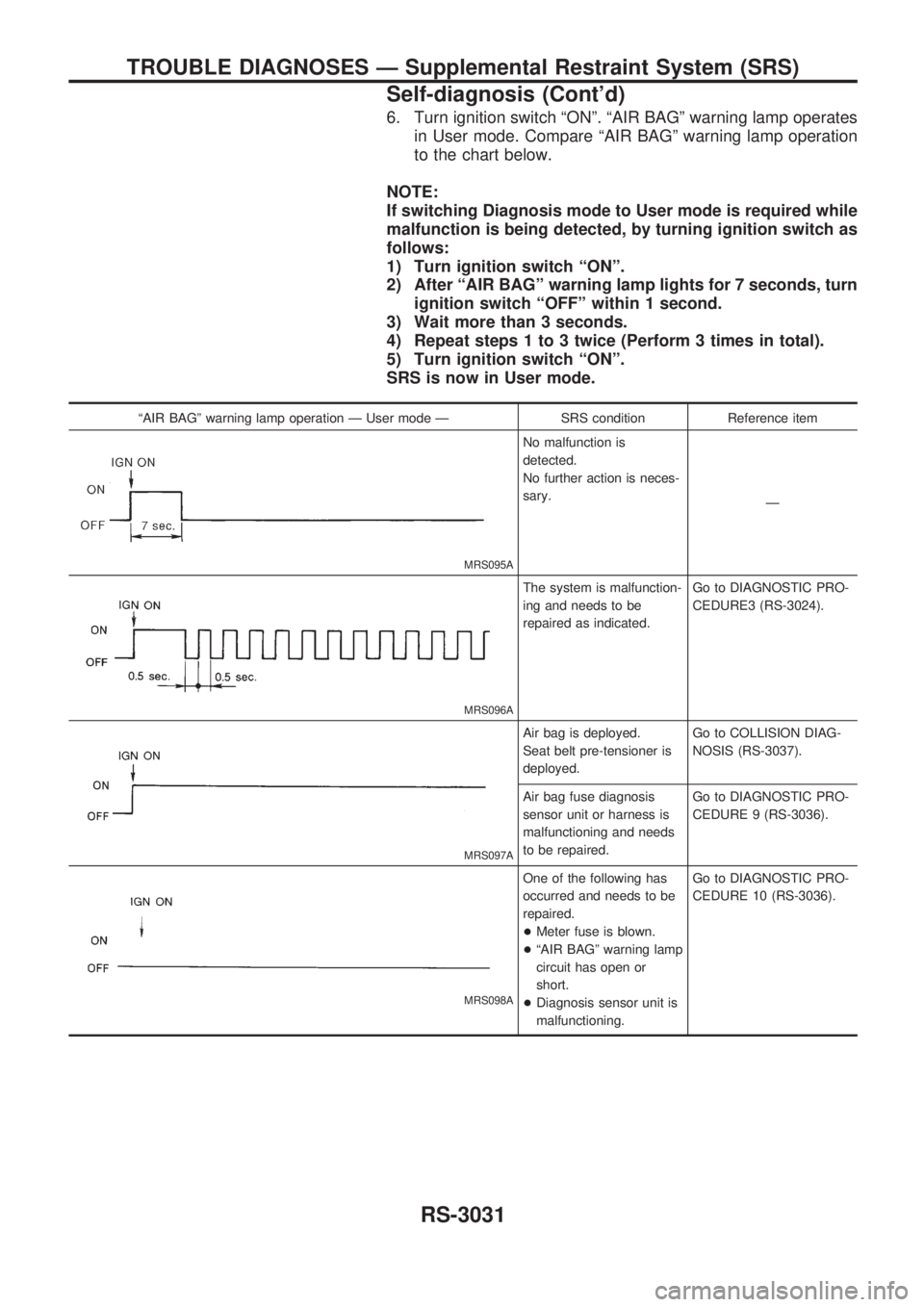
6. Turn ignition switch ªONº. ªAIR BAGº warning lamp operates
in User mode. Compare ªAIR BAGº warning lamp operation
to the chart below.
NOTE:
If switching Diagnosis mode to User mode is required while
malfunction is being detected, by turning ignition switch as
follows:
1) Turn ignition switch ªONº.
2) After ªAIR BAGº warning lamp lights for 7 seconds, turn
ignition switch ªOFFº within 1 second.
3) Wait more than 3 seconds.
4) Repeat steps 1 to 3 twice (Perform 3 times in total).
5) Turn ignition switch ªONº.
SRS is now in User mode.
ªAIR BAGº warning lamp operation Ð User mode Ð SRS condition Reference item
MRS095A
No malfunction is
detected.
No further action is neces-
sary.
Ð
MRS096A
The system is malfunction-
ing and needs to be
repaired as indicated.Go to DIAGNOSTIC PRO-
CEDURE3 (RS-3024).
MRS097A
Air bag is deployed.
Seat belt pre-tensioner is
deployed.Go to COLLISION DIAG-
NOSIS (RS-3037).
Air bag fuse diagnosis
sensor unit or harness is
malfunctioning and needs
to be repaired.Go to DIAGNOSTIC PRO-
CEDURE 9 (RS-3036).
MRS098A
One of the following has
occurred and needs to be
repaired.
+Meter fuse is blown.
+ªAIR BAGº warning lamp
circuit has open or
short.
+Diagnosis sensor unit is
malfunctioning.Go to DIAGNOSTIC PRO-
CEDURE 10 (RS-3036).
TROUBLE DIAGNOSES Ð Supplemental Restraint System (SRS)
Self-diagnosis (Cont'd)
RS-3031
Page 1133 of 1306
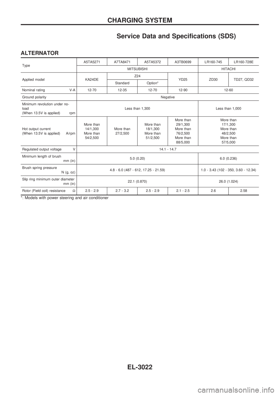
Service Data and Specifications (SDS)
ALTERNATOR
TypeA5TA5271 A7TA8471 A5TA5372 A3TB0699 LR160-745 LR160-728E
MITSUBISHI HITACHI
Applied model KA24DEZ24
YD25 ZD30 TD27, QD32
Standard Option*
Nominal rating V-A 12-70 12-35 12-70 12-90 12-60
Ground polarityNegative
Minimum revolution under no-
load
(When 13.5V is applied) rpmLess than 1,300 Less than 1,000
Hot output current
(When 13.5V is applied) A/rpmMore than
14/1,300
More than
54/2,500More than
27/2,500More than
18/1,300
More than
51/2,500More than
29/1,300
More than
76/2,500
More than
88/5,000More than
17/1,300
More than
48/2,500
More than
57/5,000
Regulated output voltage V 14.1 - 14.7
Minimum length of brush
mm (in)5.0 (0.20) 6.0 (0.236)
Brush spring pressure
N (g, oz)4.8 - 6.0 (487 - 612, 17.25 - 21.59) 1.0 - 3.43 (102 - 350, 3.60 - 12.34)
Slip ring minimum outer diameter
mm (in)22.1 (0.870) 26.0 (1.024)
Rotor (Field coil) resistanceW2.5 - 2.9 2.7 - 3.2 2.5 - 2.9 2.1 - 2.5 2.6 2.58
*: Models with power steering and air conditioner
CHARGING SYSTEM
EL-3022