2001 NISSAN PICK-UP air condition
[x] Cancel search: air conditionPage 675 of 1306
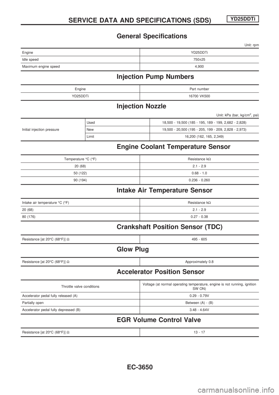
General Specifications
Unit: rpm
EngineYD25DDTi
Idle speed750 25
Maximum engine speed4,900
Injection Pump Numbers
Engine Part number
YD25DDTi 16700 VK500
Injection Nozzle
Unit: kPa (bar, kg/cm2, psi)
Initial injection pressureUsed 18,500 - 19,500 (185 - 195, 189 - 199, 2,682 - 2,828)
New 19,500 - 20,500 (195 - 205, 199 - 209, 2,828 - 2,973)
Limit 16,200 (162, 165, 2,349)
Engine Coolant Temperature Sensor
Temperature ÉC (ÉF) Resistance kW
20 (68) 2.1 - 2.9
50 (122) 0.68 - 1.0
90 (194) 0.236 - 0.260
Intake Air Temperature Sensor
Intake air temperature ÉC (ÉF)Resistance kW
20 (68)2.1 - 2.9
80 (176)0.27 - 0.38
Crankshaft Position Sensor (TDC)
Resistance [at 20ÉC (68ÉF)]W495 - 605
Glow Plug
Resistance [at 20ÉC (68ÉF)]WApproximately 0.8
Accelerator Position Sensor
Throttle valve conditionsVoltage (at normal operating temperature, engine is not running, ignition
SW ON)
Accelerator pedal fully released (A) 0.29 - 0.79V
Partially openBetween (A) - (B)
Accelerator pedal fully depressed (B) 3.48 - 4.64V
EGR Volume Control Valve
Resistance [at 20ÉC (68ÉF)]W13-17
SERVICE DATA AND SPECIFICATIONS (SDS)YD25DDTi
EC-3650
Page 697 of 1306
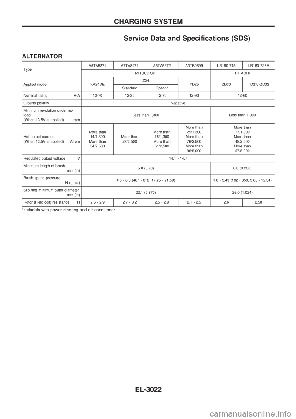
Service Data and Specifications (SDS)
ALTERNATOR
TypeA5TA5271 A7TA8471 A5TA5372 A3TB0699 LR160-745 LR160-728E
MITSUBISHI HITACHI
Applied model KA24DEZ24
YD25 ZD30 TD27, QD32
Standard Option*
Nominal rating V-A 12-70 12-35 12-70 12-90 12-60
Ground polarityNegative
Minimum revolution under no-
load
(When 13.5V is applied) rpmLess than 1,300 Less than 1,000
Hot output current
(When 13.5V is applied) A/rpmMore than
14/1,300
More than
54/2,500More than
27/2,500More than
18/1,300
More than
51/2,500More than
29/1,300
More than
76/2,500
More than
88/5,000More than
17/1,300
More than
48/2,500
More than
57/5,000
Regulated output voltage V 14.1 - 14.7
Minimum length of brush
mm (in)5.0 (0.20) 6.0 (0.236)
Brush spring pressure
N (g, oz)4.8 - 6.0 (487 - 612, 17.25 - 21.59) 1.0 - 3.43 (102 - 350, 3.60 - 12.34)
Slip ring minimum outer diameter
mm (in)22.1 (0.870) 26.0 (1.024)
Rotor (Field coil) resistanceW2.5 - 2.9 2.7 - 3.2 2.5 - 2.9 2.1 - 2.5 2.6 2.58
*: Models with power steering and air conditioner
CHARGING SYSTEM
EL-3022
Page 807 of 1306
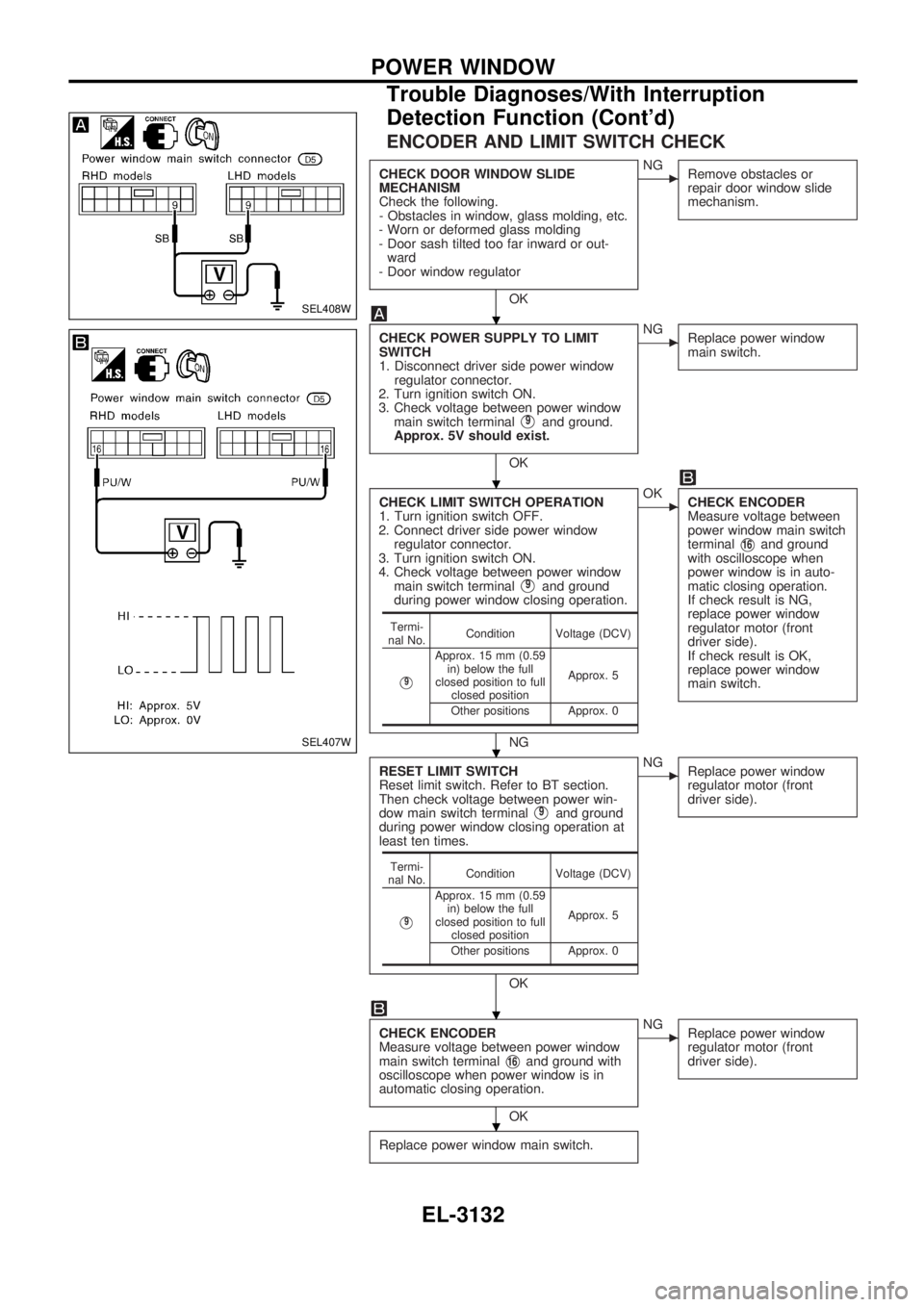
ENCODER AND LIMIT SWITCH CHECK
CHECK DOOR WINDOW SLIDE
MECHANISM
Check the following.
- Obstacles in window, glass molding, etc.
- Worn or deformed glass molding
- Door sash tilted too far inward or out-
ward
- Door window regulator
OK
cNG
Remove obstacles or
repair door window slide
mechanism.
CHECK POWER SUPPLY TO LIMIT
SWITCH
1. Disconnect driver side power window
regulator connector.
2. Turn ignition switch ON.
3. Check voltage between power window
main switch terminal
V9and ground.
Approx. 5V should exist.
OK
cNG
Replace power window
main switch.
CHECK LIMIT SWITCH OPERATION
1. Turn ignition switch OFF.
2. Connect driver side power window
regulator connector.
3. Turn ignition switch ON.
4. Check voltage between power window
main switch terminal
V9and ground
during power window closing operation.
NG
cOK
CHECK ENCODER
Measure voltage between
power window main switch
terminal
V16and ground
with oscilloscope when
power window is in auto-
matic closing operation.
If check result is NG,
replace power window
regulator motor (front
driver side).
If check result is OK,
replace power window
main switch.
RESET LIMIT SWITCH
Reset limit switch. Refer to BT section.
Then check voltage between power win-
dow main switch terminal
V9and ground
during power window closing operation at
least ten times.
OK
cNG
Replace power window
regulator motor (front
driver side).
CHECK ENCODER
Measure voltage between power window
main switch terminal
V16and ground with
oscilloscope when power window is in
automatic closing operation.
OK
cNG
Replace power window
regulator motor (front
driver side).
Replace power window main switch.
Termi-
nal No.Condition Voltage (DCV)
V9
Approx. 15 mm (0.59
in) below the full
closed position to full
closed positionApprox. 5
Other positions Approx. 0
Termi-
nal No.Condition Voltage (DCV)
V9
Approx. 15 mm (0.59
in) below the full
closed position to full
closed positionApprox. 5
Other positions Approx. 0
SEL408W
SEL407W
.
.
.
.
.
POWER WINDOW
Trouble Diagnoses/With Interruption
Detection Function (Cont'd)
EL-3132
Page 824 of 1306
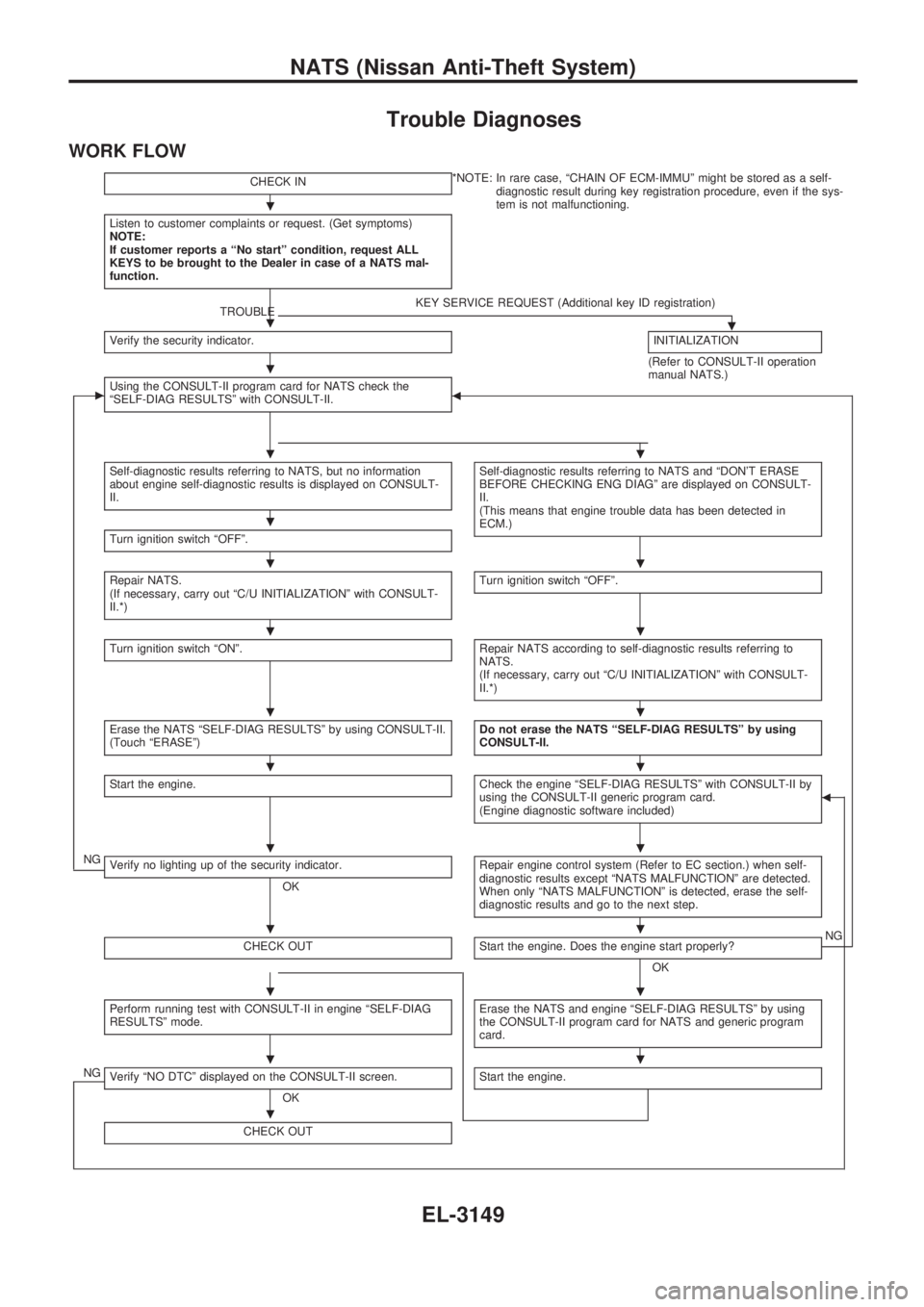
Trouble Diagnoses
WORK FLOW
CHECK IN*NOTE: In rare case, ªCHAIN OF ECM-IMMUº might be stored as a self-
diagnostic result during key registration procedure, even if the sys-
tem is not malfunctioning.
Listen to customer complaints or request. (Get symptoms)
NOTE:
If customer reports a ªNo startº condition, request ALL
KEYS to be brought to the Dealer in case of a NATS mal-
function.
TROUBLEKEY SERVICE REQUEST (Additional key ID registration).Verify the security indicator.INITIALIZATION
(Refer to CONSULT-II operation
manual NATS.)
cUsing the CONSULT-II program card for NATS check the
ªSELF-DIAG RESULTSº with CONSULT-II.b
Self-diagnostic results referring to NATS, but no information
about engine self-diagnostic results is displayed on CONSULT-
II.Self-diagnostic results referring to NATS and ªDON'T ERASE
BEFORE CHECKING ENG DIAGº are displayed on CONSULT-
II.
(This means that engine trouble data has been detected in
ECM.)
Turn ignition switch ªOFFº.
Repair NATS.
(If necessary, carry out ªC/U INITIALIZATIONº with CONSULT-
II.*)Turn ignition switch ªOFFº.
Turn ignition switch ªONº.Repair NATS according to self-diagnostic results referring to
NATS.
(If necessary, carry out ªC/U INITIALIZATIONº with CONSULT-
II.*)
Erase the NATS ªSELF-DIAG RESULTSº by using CONSULT-II.
(Touch ªERASEº)Do not erase the NATS ªSELF-DIAG RESULTSº by using
CONSULT-II.
Start the engine.Check the engine ªSELF-DIAG RESULTSº with CONSULT-II by
using the CONSULT-II generic program card.
(Engine diagnostic software included)b
NGVerify no lighting up of the security indicator.
OKRepair engine control system (Refer to EC section.) when self-
diagnostic results except ªNATS MALFUNCTIONº are detected.
When only ªNATS MALFUNCTIONº is detected, erase the self-
diagnostic results and go to the next step.
CHECK OUTStart the engine. Does the engine start properly?
OKNG
Perform running test with CONSULT-II in engine ªSELF-DIAG
RESULTSº mode.Erase the NATS and engine ªSELF-DIAG RESULTSº by using
the CONSULT-II program card for NATS and generic program
card.
NGVerify ªNO DTCº displayed on the CONSULT-II screen.
OKStart the engine.
CHECK OUT
.
.
.
..
.
..
..
..
..
..
..
..
..
.
NATS (Nissan Anti-Theft System)
EL-3149
Page 869 of 1306
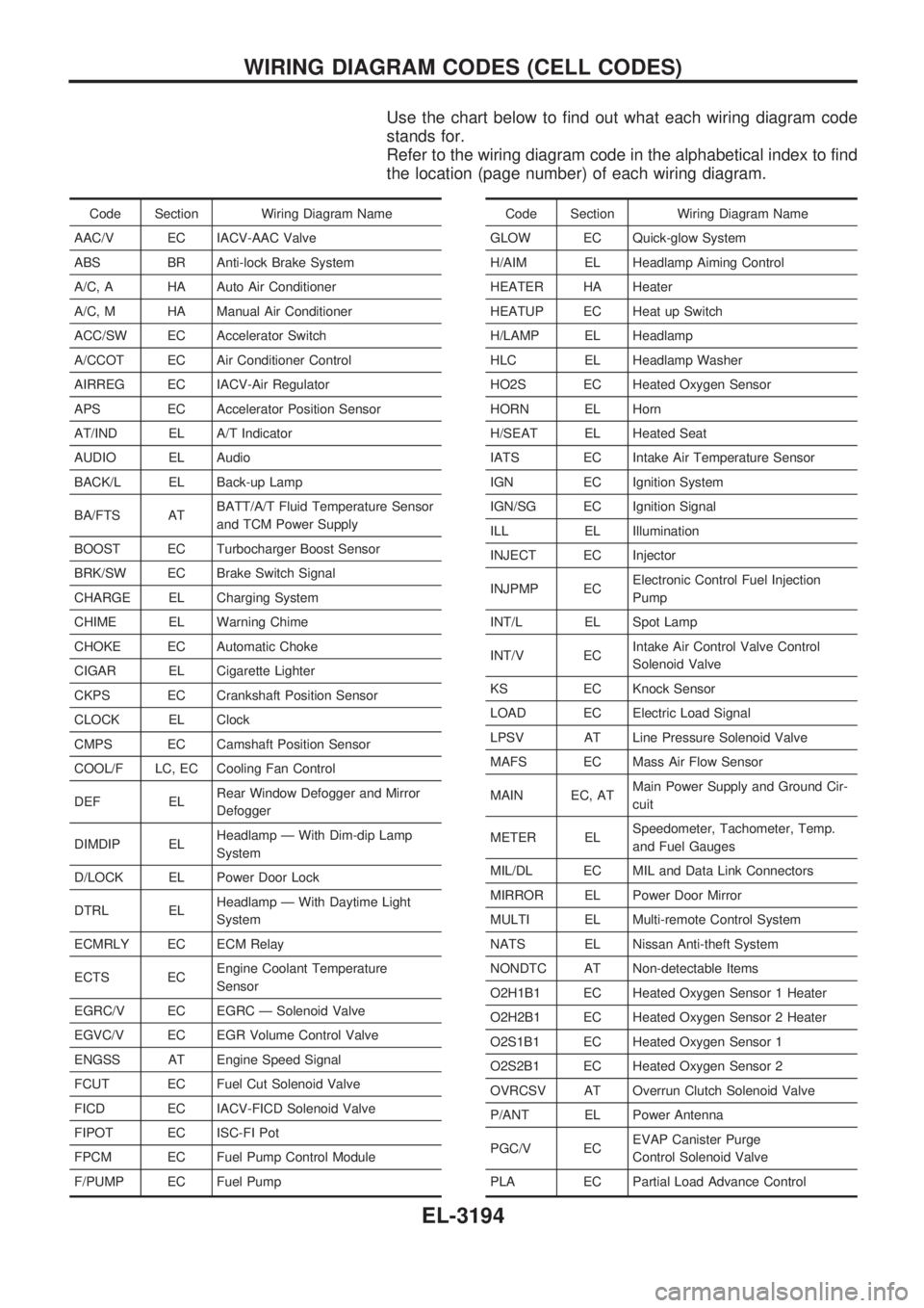
Use the chart below to find out what each wiring diagram code
stands for.
Refer to the wiring diagram code in the alphabetical index to find
the location (page number) of each wiring diagram.
Code Section Wiring Diagram Name
AAC/V EC IACV-AAC Valve
ABS BR Anti-lock Brake System
A/C, A HA Auto Air Conditioner
A/C, M HA Manual Air Conditioner
ACC/SW EC Accelerator Switch
A/CCOT EC Air Conditioner Control
AIRREG EC IACV-Air Regulator
APS EC Accelerator Position Sensor
AT/IND EL A/T Indicator
AUDIO EL Audio
BACK/L EL Back-up Lamp
BA/FTS ATBATT/A/T Fluid Temperature Sensor
and TCM Power Supply
BOOST EC Turbocharger Boost Sensor
BRK/SW EC Brake Switch Signal
CHARGE EL Charging System
CHIME EL Warning Chime
CHOKE EC Automatic Choke
CIGAR EL Cigarette Lighter
CKPS EC Crankshaft Position Sensor
CLOCK EL Clock
CMPS EC Camshaft Position Sensor
COOL/F LC, EC Cooling Fan Control
DEF ELRear Window Defogger and Mirror
Defogger
DIMDIP ELHeadlamp Ð With Dim-dip Lamp
System
D/LOCK EL Power Door Lock
DTRL ELHeadlamp Ð With Daytime Light
System
ECMRLY EC ECM Relay
ECTS ECEngine Coolant Temperature
Sensor
EGRC/V EC EGRC Ð Solenoid Valve
EGVC/V EC EGR Volume Control Valve
ENGSS AT Engine Speed Signal
FCUT EC Fuel Cut Solenoid Valve
FICD EC IACV-FICD Solenoid Valve
FIPOT EC ISC-FI Pot
FPCM EC Fuel Pump Control Module
F/PUMP EC Fuel PumpCode Section Wiring Diagram Name
GLOW EC Quick-glow System
H/AIM EL Headlamp Aiming Control
HEATER HA Heater
HEATUP EC Heat up Switch
H/LAMP EL Headlamp
HLC EL Headlamp Washer
HO2S EC Heated Oxygen Sensor
HORN EL Horn
H/SEAT EL Heated Seat
IATS EC Intake Air Temperature Sensor
IGN EC Ignition System
IGN/SG EC Ignition Signal
ILL EL Illumination
INJECT EC Injector
INJPMP ECElectronic Control Fuel Injection
Pump
INT/L EL Spot Lamp
INT/V ECIntake Air Control Valve Control
Solenoid Valve
KS EC Knock Sensor
LOAD EC Electric Load Signal
LPSV AT Line Pressure Solenoid Valve
MAFS EC Mass Air Flow Sensor
MAIN EC, ATMain Power Supply and Ground Cir-
cuit
METER ELSpeedometer, Tachometer, Temp.
and Fuel Gauges
MIL/DL EC MIL and Data Link Connectors
MIRROR EL Power Door Mirror
MULTI EL Multi-remote Control System
NATS EL Nissan Anti-theft System
NONDTC AT Non-detectable Items
O2H1B1 EC Heated Oxygen Sensor 1 Heater
O2H2B1 EC Heated Oxygen Sensor 2 Heater
O2S1B1 EC Heated Oxygen Sensor 1
O2S2B1 EC Heated Oxygen Sensor 2
OVRCSV AT Overrun Clutch Solenoid Valve
P/ANT EL Power Antenna
PGC/V ECEVAP Canister Purge
Control Solenoid Valve
PLA EC Partial Load Advance Control
WIRING DIAGRAM CODES (CELL CODES)
EL-3194
Page 889 of 1306
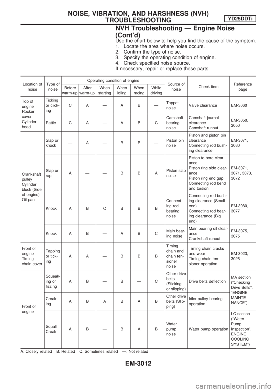
Use the chart below to help you find the cause of the symptom.
1. Locate the area where noise occurs.
2. Confirm the type of noise.
3. Specify the operating condition of engine.
4. Check specified noise source.
If necessary, repair or replace these parts.
Location of
noiseType of
noiseOperating condition of engine
Source of
noiseCheck itemReference
page Before
warm-upAfter
warm-upWhen
startingWhen
idlingWhen
racingWhile
driving
Top of
engine
Rocker
cover
Cylinder
headTicking
or click-
ingCAÐABÐTappet
noiseValve clearance EM-3060
Rattle C A Ð A B CCamshaft
bearing
noiseCamshaft journal
clearance
Camshaft runoutEM-3050,
3050
Crankshaft
pulley
Cylinder
block (Side
of engine)
Oil panSlap or
knockÐAÐB BÐPiston pin
noisePiston and piston pin
clearance
Connecting rod bush-
ing clearanceEM-3071,
3080
Slap or
rapAÐÐBBAPiston slap
noisePiston-to-bore clear-
ance
Piston ring side clear-
ance
Piston ring end gap
Connecting rod bend
and torsionEM-3071,
3071, 3073,
3072
Knock A B C B B BConnect-
ing rod
bearing
noiseConnecting rod bush-
ing clearance (Small
end)
Connecting rod bear-
ing clearance (Big
end)EM-3080,
3077
Knock A B Ð A B CMain bear-
ing noiseMain bearing oil clear-
ance
Crankshaft runoutEM-3075,
3075
Front of
engine
Timing
chain coverTapping
or tick-
ingAAÐBBBTiming
chain and
chain ten-
sioner
noiseTiming chain cracks
and wear
Timing chain ten-
sioner operationEM-3023,
3026
Front of
engineSqueak-
ing or
fizzingABÐBÐCOther drive
belts
(Sticking
or slipping)Drive belts deflectionMA section
(ªChecking
Drive Beltsº,
ªENGINE
MAINTE-
NANCEº) Creak-
ingABABABOther drive
belts (Slip-
ping)Idler pulley bearing
operation
Squall
CreakABÐBABWater
pump
noiseWater pump operationLC section
(ªWater
Pump
Inspectionº,
ENGINE
COOLING
SYSTEMº)
A: Closely related B: Related C: Sometimes related Ð: Not related
NOISE, VIBRATION, AND HARSHNESS (NVH)
TROUBLESHOOTINGYD25DDTi
NVH Troubleshooting Ð Engine Noise
(Cont'd)
EM-3012
Page 894 of 1306

5. Remove lower oil pan.
a. Insert Tool between upper oil pan and lower oil pan.
+Be careful not to damage aluminum mating surface.
+ Do not insert screwdriver, or oil pan flange will be
deformed.
b. Slide Tool by tapping on the side of the Tool with a hammer.
c. Remove lower oil pan.
6. Remove oil strainer.
7. Remove air conditioner compressor and bracket.
8. Remove left side of the tie rod end Ð 2WD models only.
9. Remove front final drive together with differential mounting member and front suspension member. Refer to PD, MT and
FAsectionsinNISSANServiceManual(First Edition of
SM3E00-1D22E0E) Ð 4WD models only.
10.Removecrankshaftpositionsensor.RefertoEM sectionin NISSANServiceManual(Supplement III of SM3E00-
1D22E0E).
11. Remove transmission. Refer to MT section in NISSAN Ser- viceManual(Supplement III of SM3E00-1D22E0E)Ð2WD
models only.
12. Remove transmission with transfer assembly. Refer to MT sectioninNISSANServiceManual(Supplement III of
SM3E00-1D22E0E) Ð 4WD models only.
13. Remove clutch cover and clutch disc. Refer to CL section in NISSANServiceManual(Supplement I of SM3E00-
1D22E0E).
14. Remove flywheel and engine rear plate. Refer to EM section (``Disassembly'', ``CYLINDER BLOCK'') in NISSAN Service
Manual(Supplement III of SM3E00-1D22E0E).
SEM852G
SEM865G
SEM600F
OILPAN YD25DDTi
Removal (Cont'd)
EM-3017
Page 896 of 1306
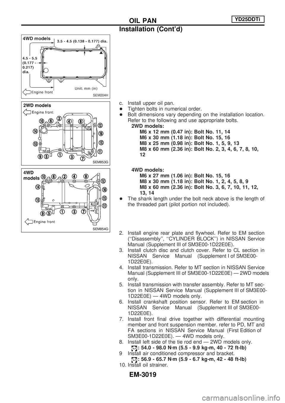
c. Install upper oil pan.
+Tighten bolts in numerical order.
+ Bolt dimensions vary depending on the installation location.
Refer to the following and use appropriate bolts.
2WD models: M6 x 12 mm (0.47 in): Bolt No. 11, 14
M6 x 30 mm (1.18 in): Bolt No. 15, 16
M8 x 25 mm (0.98 in): Bolt No. 1, 5, 9, 13
M8 x 60 mm (2.36 in): Bolt No. 2, 3, 4, 6, 7, 8, 10,
12
4WD models: M6 x 27 mm (1.06 in): Bolt No. 15, 16
M8 x 30 mm (1.18 in): Bolt No. 1, 2, 4, 5, 8, 9
M8 x 60 mm (2.36 in): Bolt No. 3, 6, 7, 10, 11, 12,
13, 14
+ The shank length under the bolt neck above is the length of
the threaded part (pilot portion not included).
2. Install engine rear plate and flywheel. Refer to EM section (``Disassembly'', ``CYLINDER BLOCK'') in NISSAN Service
Manual(Supplement III of SM3E00-1D22E0E).
3. Install clutch disc and clutch cover. Refer to CL section in NISSANServiceManual(Supplement I of SM3E00-
1D22E0E).
4. Install transmission. Refer to MT section in NISSAN Service Manual(Supplement III of SM3E00-1D22E0E)Ð2WDmodels
only.
5. Install transmission with transfer assembly. Refer to MT sec- tioninNISSANServiceManual(Supplement III of SM3E00-
1D22E0E) Ð 4WD models only.
6.Installcrankshaftpositionsensor.RefertoEM sectionin NISSANServiceManual(Supplement III of SM3E00-
1D22E0E).
7. Install front final drive together with differential mounting member and front suspension member. refer to PD, MT and
FAsectionsinNISSANServiceManual(First Edition of
SM3E00-1D22E0E). Ð 4WD models only.
8. Install left side of the tie rod end Ð 2WD models only.
: 54.0 - 98.0 N zm (5.5 - 9.9 kg-m, 40 - 72 ft-lb)
9 Install air conditioned compressor and bracket.
: 56.9 - 65.7 N zm (5.9 - 6.7 kg-m, 42 - 48 ft-lb)
10. Install oil strainer.
SEM204H
SEM853G
SEM854G
OILPAN YD25DDTi
Installation (Cont'd)
EM-3019