Page 615 of 1306
6 CHECK STOP LAMP SWITCH INPUT SIGNAL CIRCUIT FOR OPEN AND SHORT
1. Turn ignition switch ªOFFº.
2. Disconnect ECM harness connector.
3. Disconnect stop lamp switch harness connector.
SEC233D
4. Check harness continuity between ECM terminal 17 and stop lamp switch terminal 2. Refer to Wiring Diagram.
Continuity should exist.
5. Also check harness for short to ground and short to power.
OK or NG
OKcGO TO 8.
NGcGO TO 7.
7 DETECT MALFUNCTIONING PART
Check the following.
+Harness connectors M48, F54 (RHD models)
+Harness for open or short between stop lamp switch and ECM
cRepair open circuit or short to ground or short to power in harness or connectors.
8 CHECK STOP LAMP SWITCH
Check continuity between stop lamp switch terminal 1 and 2 under the following conditions.
SEC260D
OK or NG
OKcGO TO 14.
NGcReplace stop lamp switch.
DTC 0807 ECM 14YD25DDTi
Diagnostic Procedure (Cont'd)
EC-3590
Page 625 of 1306

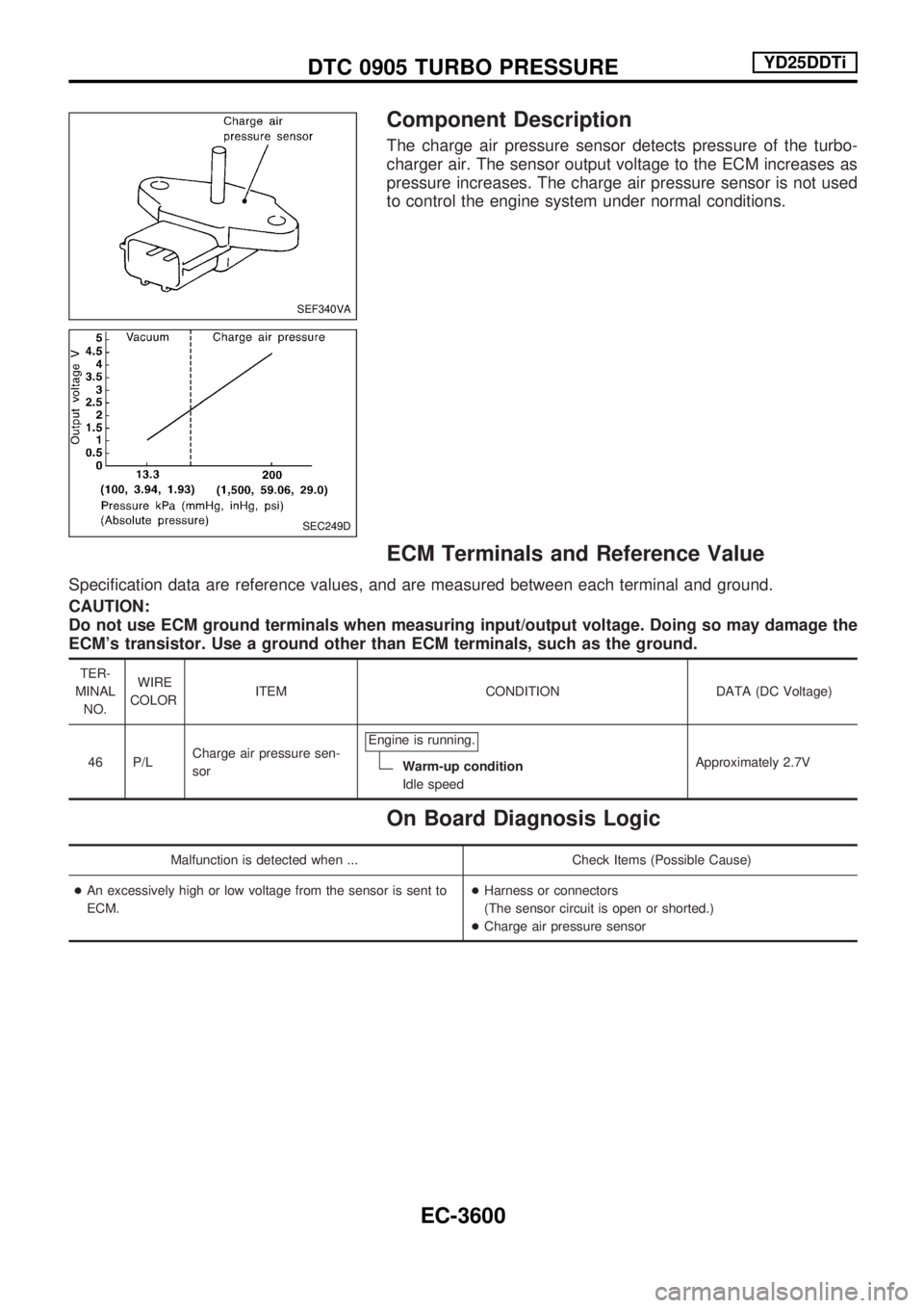
Component Description
The charge air pressure sensor detects pressure of the turbo-
charger air. The sensor output voltage to the ECM increases as
pressure increases. The charge air pressure sensor is not used
to control the engine system under normal conditions.
ECM Terminals and Reference Value
Specification data are reference values, and are measured between each terminal and ground.
CAUTION:
Do not use ECM ground terminals when measuring input/output voltage. Doing so may damage the
ECM's transistor. Use a ground other than ECM terminals, such as the ground.
TER-
MINAL
NO.WIRE
COLORITEM CONDITION DATA (DC Voltage)
46 P/LCharge air pressure sen-
sorEngine is running.
Warm-up condition
Idle speedApproximately 2.7V
On Board Diagnosis Logic
Malfunction is detected when ... Check Items (Possible Cause)
+An excessively high or low voltage from the sensor is sent to
ECM.+Harness or connectors
(The sensor circuit is open or shorted.)
+Charge air pressure sensor
SEF340VA
SEC249D
DTC 0905 TURBO PRESSUREYD25DDTi
EC-3600
Page 630 of 1306

Description
SYSTEM DESCRIPTION
Sensor Input Signal to ECM ECM Function Actuator
Electronic controlled fuel injection pump Fuel injection signal
EGR volume
controlEGR volume control valve Crankshaft position sensor (TDC) Engine speed
Vehicle speed sensor Vehicle speed
Engine coolant temperature sensor Engine coolant temperature
Ignition switch Start signal
Accelerator position sensor Accelerator position
Battery Battery voltage
Air conditioner switch Air conditioner operation
PNP switch Park/Neutral position signal
Barometric pressure sensor (Built into
ECM)Barometric pressure
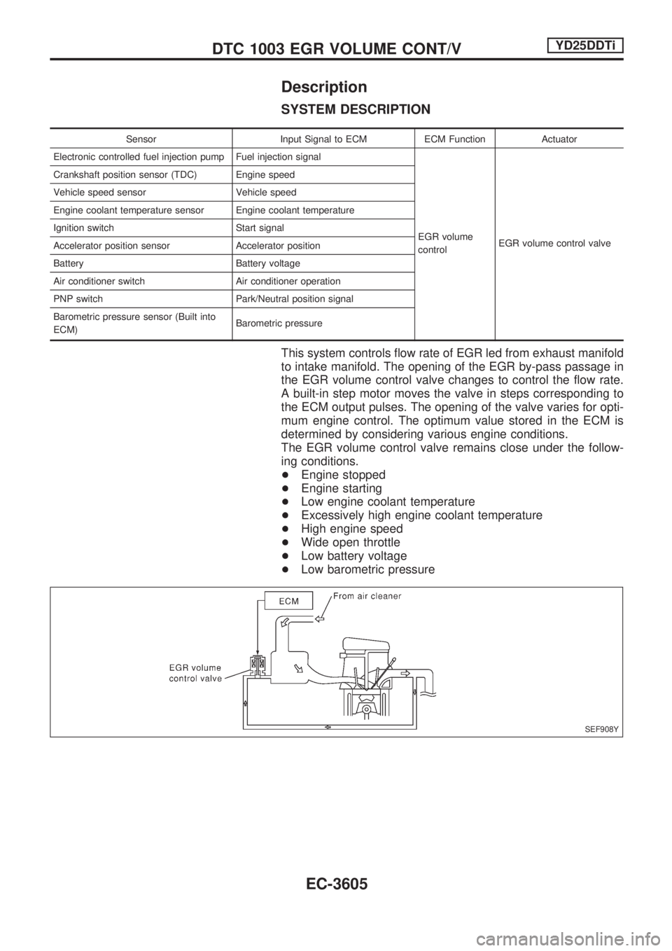
This system controls flow rate of EGR led from exhaust manifold
to intake manifold. The opening of the EGR by-pass passage in
the EGR volume control valve changes to control the flow rate.
A built-in step motor moves the valve in steps corresponding to
the ECM output pulses. The opening of the valve varies for opti-
mum engine control. The optimum value stored in the ECM is
determined by considering various engine conditions.
The EGR volume control valve remains close under the follow-
ing conditions.
+Engine stopped
+Engine starting
+Low engine coolant temperature
+Excessively high engine coolant temperature
+High engine speed
+Wide open throttle
+Low battery voltage
+Low barometric pressure
SEF908Y
DTC 1003 EGR VOLUME CONT/VYD25DDTi
EC-3605
Page 631 of 1306

COMPONENT DESCRIPTION
EGR volume control valve
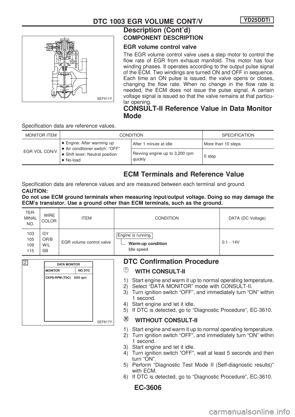
The EGR volume control valve uses a step motor to control the
flow rate of EGR from exhaust manifold. This motor has four
winding phases. It operates according to the output pulse signal
of the ECM. Two windings are turned ON and OFF in sequence.
Each time an ON pulse is issued, the valve opens or closes,
changing the flow rate. When no change in the flow rate is
needed, the ECM does not issue the pulse signal. A certain
voltage signal is issued so that the valve remains at that particu-
lar opening.
CONSULT-II Reference Value in Data Monitor
Mode
Specification data are reference values.
MONITOR ITEM CONDITION SPECIFICATION
EGR VOL CON/V+Engine: After warming up
+Air conditioner switch: ªOFFº
+Shift lever: Neutral position
+No-loadAfter 1 minute at idle More than 10 steps
Revving engine up to 3,200 rpm
quickly0 step
ECM Terminals and Reference Value
Specification data are reference values and are measured between each terminal and ground.
CAUTION:
Do not use ECM ground terminals when measuring input/output voltage. Doing so may damage the
ECM's transistor. Use a ground other than ECM terminals, such as the ground.
TER-
MINAL
NO.WIRE
COLORITEM CONDITION DATA (DC Voltage)
103
105
109
115GY
OR/B
W/L
SBEGR volume control valveEngine is running.
Warm-up condition
Idle speed0.1 - 14V
DTC Confirmation Procedure
WITH CONSULT-II
1) Start engine and warm it up to normal operating temperature.
2) Select ªDATA MONITORº mode with CONSULT-II.
3) Turn ignition switch ªOFFº, and immediately turn ªONº within
1 second.
4) Start engine and let it idle.
5) If DTC is detected, go to ªDiagnostic Procedureº, EC-3610.
WITHOUT CONSULT-II
1) Start engine and warm it up to normal operating temperature.
2) Turn ignition switch ªOFFº, and immediately turn ªONº within
1 second.
3) Start engine and let it idle.
4) Turn ignition switch ªOFFº, wait at least 5 seconds and then
turn ªONº.
5) Perform ªDiagnostic Test Mode II (Self-diagnostic results)º
with ECM.
6) If DTC is detected, go to ªDiagnostic Procedureº, EC-3610.
SEF411Y
SEF817Y
DTC 1003 EGR VOLUME CONT/VYD25DDTi
Description (Cont'd)
EC-3606
Page 653 of 1306

13 CHECK GLOW RELAY OUTPUT SIGNAL CIRCUIT FOR OPEN AND SHORT
1. Disconnect ECM harness connector.
2. Check harness continuity between ECM terminal 111 and glow relay terminal 2. Refer to Wiring Diagram.
Continuity should exist.
3. Also check harness for short to ground and short to power.
OK or NG
OKcGO TO 15.
NGcGO TO 14.
14 DETECT MALFUNCTIONING PART
Check the following.
+Harness connectors E101, M5
+Harness connectors M48, F54 (RHD models)
+Harness for open or short between glow relay and ECM
cRepair open circuit or short to ground or short to power in harness or connectors.
15 CHECK HARNESS CONTINUITY BETWEEN GLOW RELAY AND GLOW PLUG FOR OPEN AND SHORT
1. Disconnect glow plug harness connector.
2. Check harness continuity between glow relay terminal 5 and glow plug harness connector. Refer to Wiring Diagram.
Continuity should exist.
3. Also check harness for short to ground and short to power.
OK or NG
OKcGO TO 16.
NGcRepair open circuit or short to ground or short to power in harness or connectors.
16 DETECT MALFUNCTIONING PART
Check the following.
+Harness connectors E72, E232
+Harness for open or short between glow relay and glow plug
cRepair open circuit or short to ground or short to power in harness or connectors.
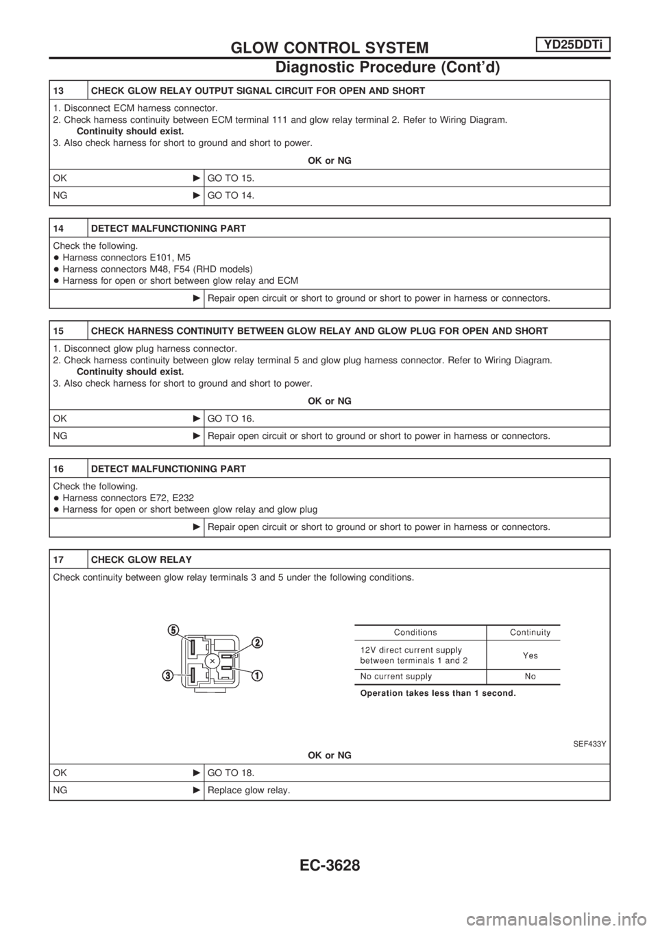
17 CHECK GLOW RELAY
Check continuity between glow relay terminals 3 and 5 under the following conditions.
SEF433Y
OK or NG
OKcGO TO 18.
NGcReplace glow relay.
GLOW CONTROL SYSTEMYD25DDTi
Diagnostic Procedure (Cont'd)
EC-3628
Page 667 of 1306

8 DETECT MALFUNCTIONING PART
Check the following.
+Harness connectors N1, M6
+Harness connectors M48, F54 (RHD models)
+Harness for open or short between heat up switch and ECM
cRepair open circuit or short to ground or short to power in harness or connectors.
9 CHECK HEAT UP SWITCH
Check continuity between heat up switch terminals 5 and 6 under the following conditions.
SEF305Z
OK or NG
OKcGO TO 13.
NGcReplace heat up switch.
10 CHECK HEAT UP SWITCH INDICATOR GROUND CIRCUIT FOR OPEN AND SHORT
1. Turn heat up switch ªOFFº.
2. Turn ignition switch ªOFFº.
3. Disconnect heat up switch harness connector.
4. Check harness continuity between heat up switch terminal 4 and ground.
Refer to Wiring Diagram.
Continuity should exist.
5. Also check harness for short to power.
OK or NG
OKcGO TO 12.
NGcGO TO 11.
11 DETECT MALFUNCTIONING PART
Check the following.
+Harness connectors N2, M7
+Harness for open or short between heat up switch and ground
cRepair open circuit or short to power in harness or connectors.
12 CHECK HEAT UP SWITCH INDICATOR
Apply 12V current supply between heat up switch terminal 4 and 6.
Indicator should illuminates.
OK or NG
OKcGO TO 13.
NGcReplace heat up switch.
HEAT UP SWITCHYD25DDTi
Diagnostic Procedure (Cont'd)
EC-3642
Page 669 of 1306
Wiring Diagram
LHD MODELS
GEC288A
AIR CONDITIONER CONTROLYD25DDTi
EC-3644
Page 670 of 1306
RHD MODELS
GEC289A
AIR CONDITIONER CONTROLYD25DDTi
Wiring Diagram (Cont'd)
EC-3645