Page 1718 of 3051
Wiring DiagramNLEC0769MODELS WITH ECM IN ENGINE COMPARTMENTNLEC0769S01
YEC738
START SIGNALYD22DDTI
Wiring Diagram
EC-1293
Page 1719 of 3051
MODELS WITH ECM IN CABINNLEC0769S02
YEC868
START SIGNALYD22DDTI
Wiring Diagram (Cont'd)
EC-1294
Page 1720 of 3051

Diagnostic ProcedureNLEC0770
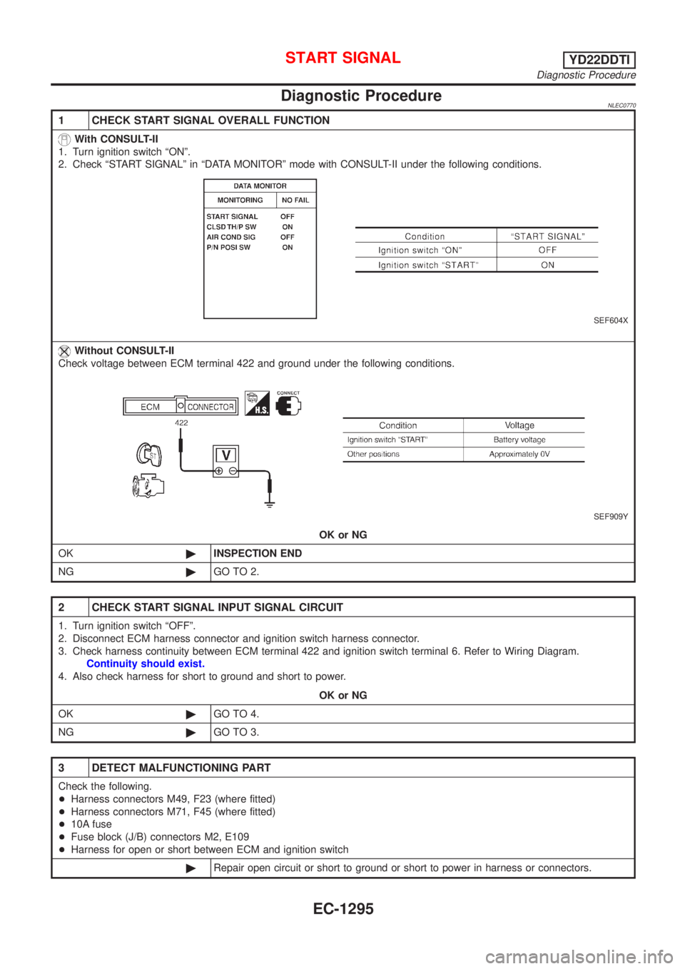
1 CHECK START SIGNAL OVERALL FUNCTION
With CONSULT-II
1. Turn ignition switch ªONº.
2. Check ªSTART SIGNALº in ªDATA MONITORº mode with CONSULT-II under the following conditions.
SEF604X
Without CONSULT-II
Check voltage between ECM terminal 422 and ground under the following conditions.
SEF909Y
OK or NG
OK©INSPECTION END
NG©GO TO 2.
2 CHECK START SIGNAL INPUT SIGNAL CIRCUIT
1. Turn ignition switch ªOFFº.
2. Disconnect ECM harness connector and ignition switch harness connector.
3. Check harness continuity between ECM terminal 422 and ignition switch terminal 6. Refer to Wiring Diagram.
Continuity should exist.
4. Also check harness for short to ground and short to power.
OK or NG
OK©GO TO 4.
NG©GO TO 3.
3 DETECT MALFUNCTIONING PART
Check the following.
+Harness connectors M49, F23 (where fitted)
+Harness connectors M71, F45 (where fitted)
+10A fuse
+Fuse block (J/B) connectors M2, E109
+Harness for open or short between ECM and ignition switch
©Repair open circuit or short to ground or short to power in harness or connectors.
START SIGNALYD22DDTI
Diagnostic Procedure
EC-1295
Page 1723 of 3051
Wiring DiagramNLEC0784
YEC734
PARK/NEUTRAL POSITION (PNP) SWITCH
(WHERE FITTED)
YD22DDTI
Wiring Diagram
EC-1298
Page 1725 of 3051

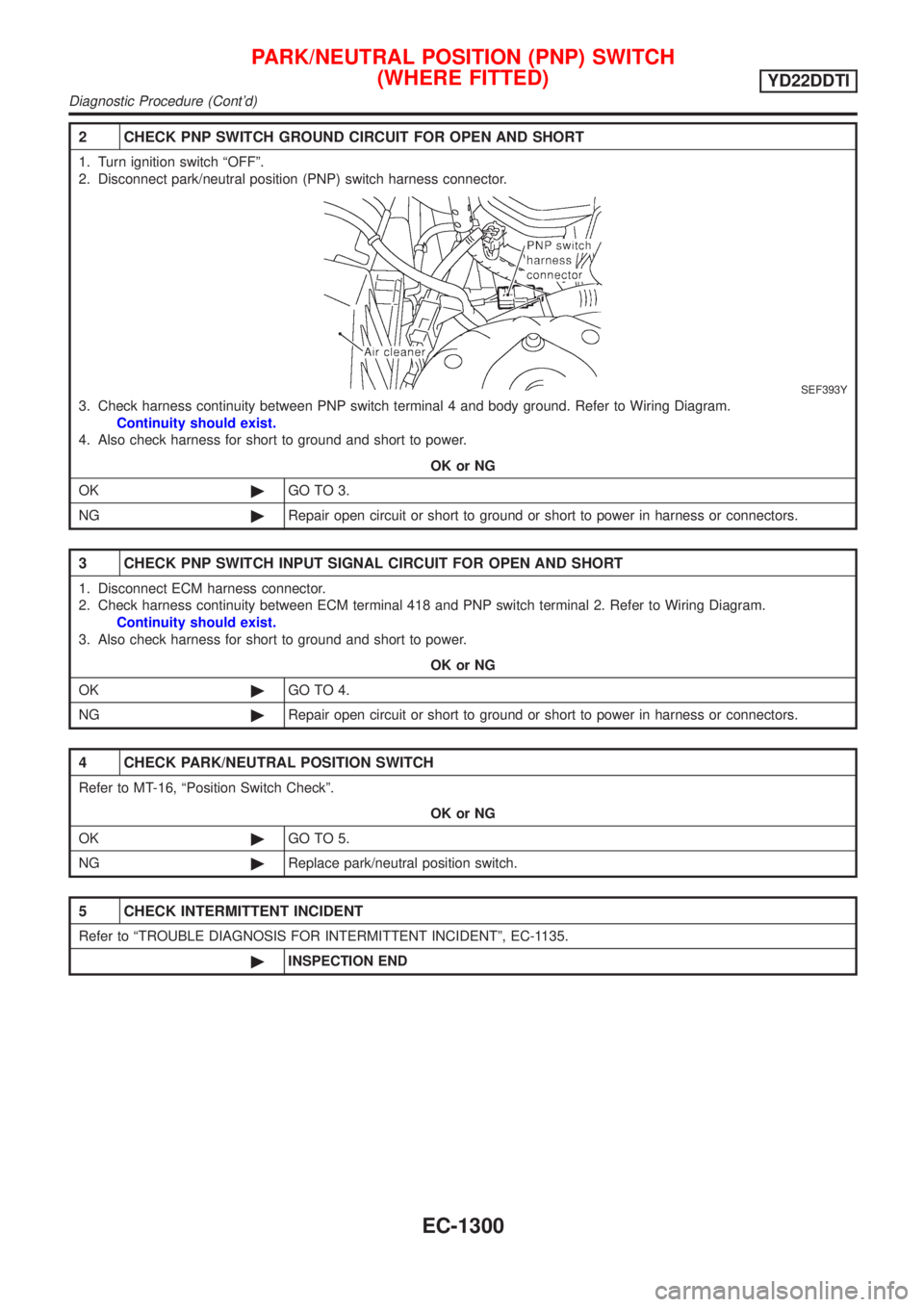
2 CHECK PNP SWITCH GROUND CIRCUIT FOR OPEN AND SHORT
1. Turn ignition switch ªOFFº.
2. Disconnect park/neutral position (PNP) switch harness connector.
SEF393Y
3. Check harness continuity between PNP switch terminal 4 and body ground. Refer to Wiring Diagram.
Continuity should exist.
4. Also check harness for short to ground and short to power.
OK or NG
OK©GO TO 3.
NG©Repair open circuit or short to ground or short to power in harness or connectors.
3 CHECK PNP SWITCH INPUT SIGNAL CIRCUIT FOR OPEN AND SHORT
1. Disconnect ECM harness connector.
2. Check harness continuity between ECM terminal 418 and PNP switch terminal 2. Refer to Wiring Diagram.
Continuity should exist.
3. Also check harness for short to ground and short to power.
OK or NG
OK©GO TO 4.
NG©Repair open circuit or short to ground or short to power in harness or connectors.
4 CHECK PARK/NEUTRAL POSITION SWITCH
Refer to MT-16, ªPosition Switch Checkº.
OK or NG
OK©GO TO 5.
NG©Replace park/neutral position switch.
5 CHECK INTERMITTENT INCIDENT
Refer to ªTROUBLE DIAGNOSIS FOR INTERMITTENT INCIDENTº, EC-1135.
©INSPECTION END
PARK/NEUTRAL POSITION (PNP) SWITCH
(WHERE FITTED)
YD22DDTI
Diagnostic Procedure (Cont'd)
EC-1300
Page 1726 of 3051
Wiring DiagramNLEC0786MODELS WITH ECM IN ENGINE COMPARTMENTNLEC0786S01
YEC735
AIR CONDITIONER CONTROLYD22DDTI
Wiring Diagram
EC-1301
Page 1727 of 3051
MODELS WITH ECM IN CABINNLEC0786S02
YEC869
AIR CONDITIONER CONTROLYD22DDTI
Wiring Diagram (Cont'd)
EC-1302
Page 1728 of 3051
Wiring DiagramNLEC0787MODELS WITH ECM IN ENGINE COMPARTMENTNLEC0787S01
YEC736
MI & DATA LINK CONNECTORSYD22DDTI
Wiring Diagram
EC-1303