Page 1675 of 3051
MODELS WITH ECM IN CABINNLEC0712S02
YEC862
DTC P1600 P3´PUMP COMM LINEYD22DDTI
Wiring Diagram (Cont'd)
EC-1250
Page 1677 of 3051
4 CHECK COMMUNICATION LINE FOR OPEN AND SHORT
1. Check continuity between the following terminals. Refer to Wiring Diagram.
MTBL0462
Continuity should exist.
2. Also check harness for short to ground and short to power.
OK or NG
OK©GO TO 5.
NG©Repair open circuit or short to ground or short to power in harness or connectors.
5 CHECK INTERMITTENT INCIDENT
Refer to ªTROUBLE DIAGNOSIS FOR INTERMITTENT INCIDENTº, EC-1135.
OK or NG
OK©Replace electronic control fuel injection pump.
NG©Repair open circuit or short to ground or short to power in harness or connectors.
DTC P1600 P3´PUMP COMM LINEYD22DDTI
Diagnostic Procedure (Cont'd)
EC-1252
Page 1681 of 3051
Wiring DiagramNLEC0747MODELS WITH ECM IN ENGINE COMPARTMENTNLEC0747S01
YEC730
DTC P1620 ECM RLYYD22DDTI
Wiring Diagram
EC-1256
Page 1682 of 3051
MODELS WITH ECM IN CABINNLEC0747S02
YEC864
DTC P1620 ECM RLYYD22DDTI
Wiring Diagram (Cont'd)
EC-1257
Page 1683 of 3051

Diagnostic ProcedureNLEC0748
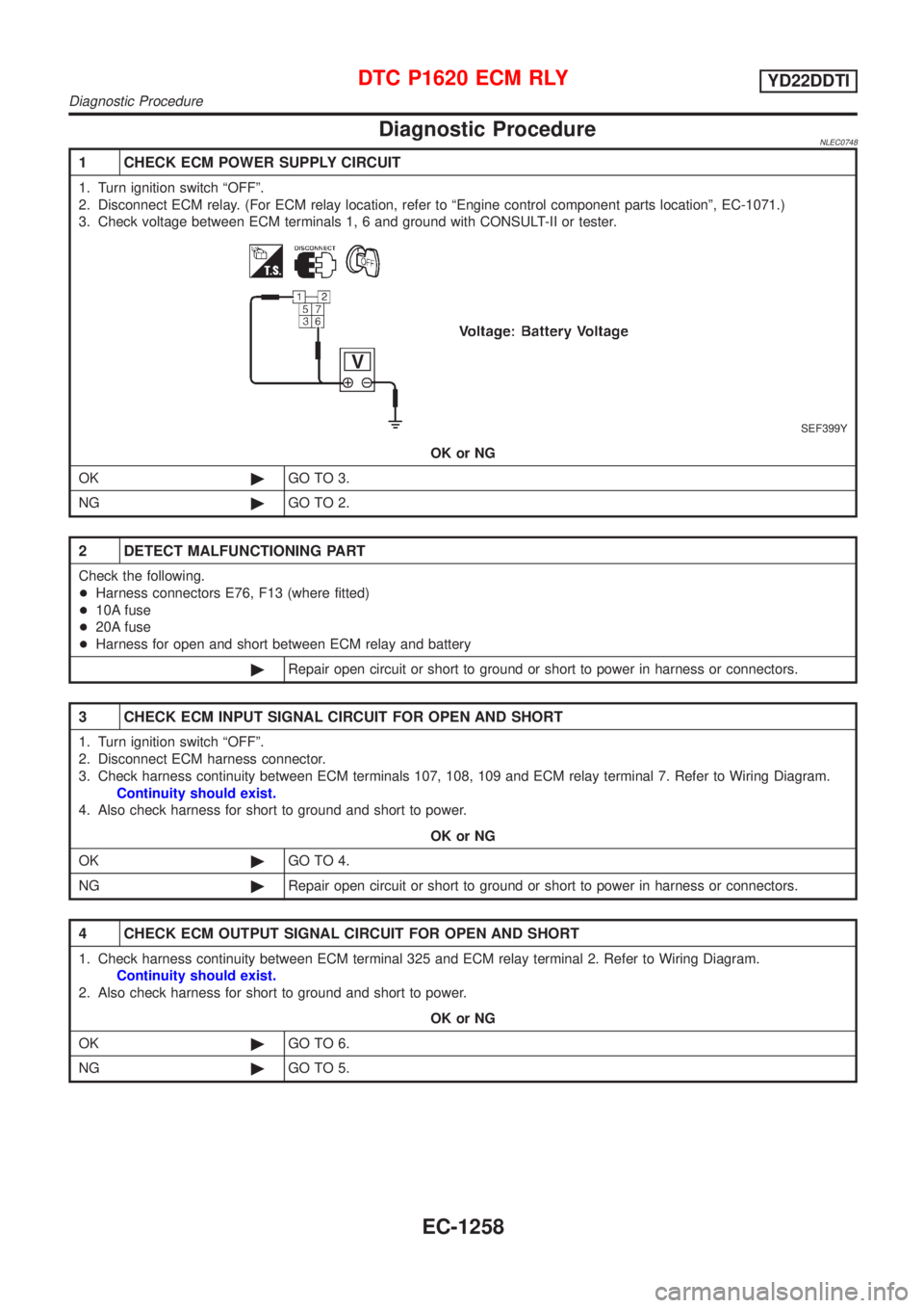
1 CHECK ECM POWER SUPPLY CIRCUIT
1. Turn ignition switch ªOFFº.
2. Disconnect ECM relay. (For ECM relay location, refer to ªEngine control component parts locationº, EC-1071.)
3. Check voltage between ECM terminals 1, 6 and ground with CONSULT-II or tester.
SEF399Y
OK or NG
OK©GO TO 3.
NG©GO TO 2.
2 DETECT MALFUNCTIONING PART
Check the following.
+Harness connectors E76, F13 (where fitted)
+10A fuse
+20A fuse
+Harness for open and short between ECM relay and battery
©Repair open circuit or short to ground or short to power in harness or connectors.
3 CHECK ECM INPUT SIGNAL CIRCUIT FOR OPEN AND SHORT
1. Turn ignition switch ªOFFº.
2. Disconnect ECM harness connector.
3. Check harness continuity between ECM terminals 107, 108, 109 and ECM relay terminal 7. Refer to Wiring Diagram.
Continuity should exist.
4. Also check harness for short to ground and short to power.
OK or NG
OK©GO TO 4.
NG©Repair open circuit or short to ground or short to power in harness or connectors.
4 CHECK ECM OUTPUT SIGNAL CIRCUIT FOR OPEN AND SHORT
1. Check harness continuity between ECM terminal 325 and ECM relay terminal 2. Refer to Wiring Diagram.
Continuity should exist.
2. Also check harness for short to ground and short to power.
OK or NG
OK©GO TO 6.
NG©GO TO 5.
DTC P1620 ECM RLYYD22DDTI
Diagnostic Procedure
EC-1258
Page 1694 of 3051
Wiring DiagramNLEC0762MODELS WITH ECM IN ENGINE COMPARTMENTNLEC0762S01
YEC731
GLOW CONTROL SYSTEMYD22DDTI
Wiring Diagram
EC-1269
Page 1695 of 3051
MODELS WITH ECM IN CABINNLEC0762S02
YEC865
GLOW CONTROL SYSTEMYD22DDTI
Wiring Diagram (Cont'd)
EC-1270
Page 1699 of 3051

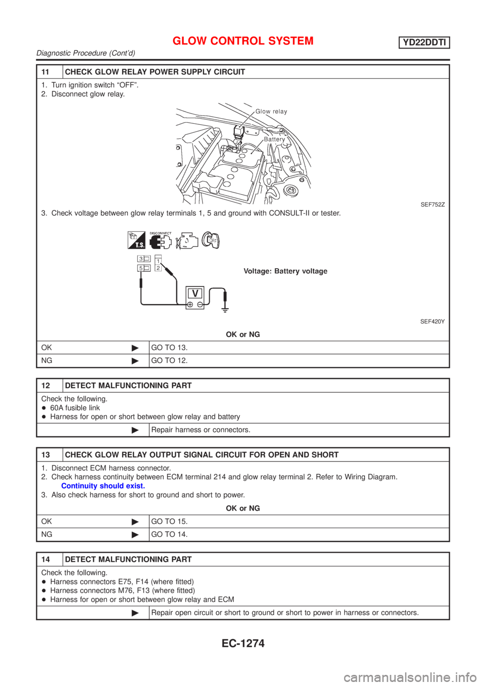
11 CHECK GLOW RELAY POWER SUPPLY CIRCUIT
1. Turn ignition switch ªOFFº.
2. Disconnect glow relay.
SEF752Z
3. Check voltage between glow relay terminals 1, 5 and ground with CONSULT-II or tester.
SEF420Y
OK or NG
OK©GO TO 13.
NG©GO TO 12.
12 DETECT MALFUNCTIONING PART
Check the following.
+60A fusible link
+Harness for open or short between glow relay and battery
©Repair harness or connectors.
13 CHECK GLOW RELAY OUTPUT SIGNAL CIRCUIT FOR OPEN AND SHORT
1. Disconnect ECM harness connector.
2. Check harness continuity between ECM terminal 214 and glow relay terminal 2. Refer to Wiring Diagram.
Continuity should exist.
3. Also check harness for short to ground and short to power.
OK or NG
OK©GO TO 15.
NG©GO TO 14.
14 DETECT MALFUNCTIONING PART
Check the following.
+Harness connectors E75, F14 (where fitted)
+Harness connectors M76, F13 (where fitted)
+Harness for open or short between glow relay and ECM
©Repair open circuit or short to ground or short to power in harness or connectors.
GLOW CONTROL SYSTEMYD22DDTI
Diagnostic Procedure (Cont'd)
EC-1274