Page 1700 of 3051

15 CHECK HARNESS CONTINUITY BETWEEN GLOW RELAY AND GLOW PLUG FOR OPEN AND SHORT
1. Disconnect glow plug harness connector.
2. Check harness continuity between glow relay terminal 3 and glow plug harness connector. Refer to Wiring Diagram.
Continuity should exist.
3. Also check harness for short to ground and short to power.
OK or NG
OK©GO TO 16.
NG©Repair open circuit or short to ground or short to power in harness or connectors.
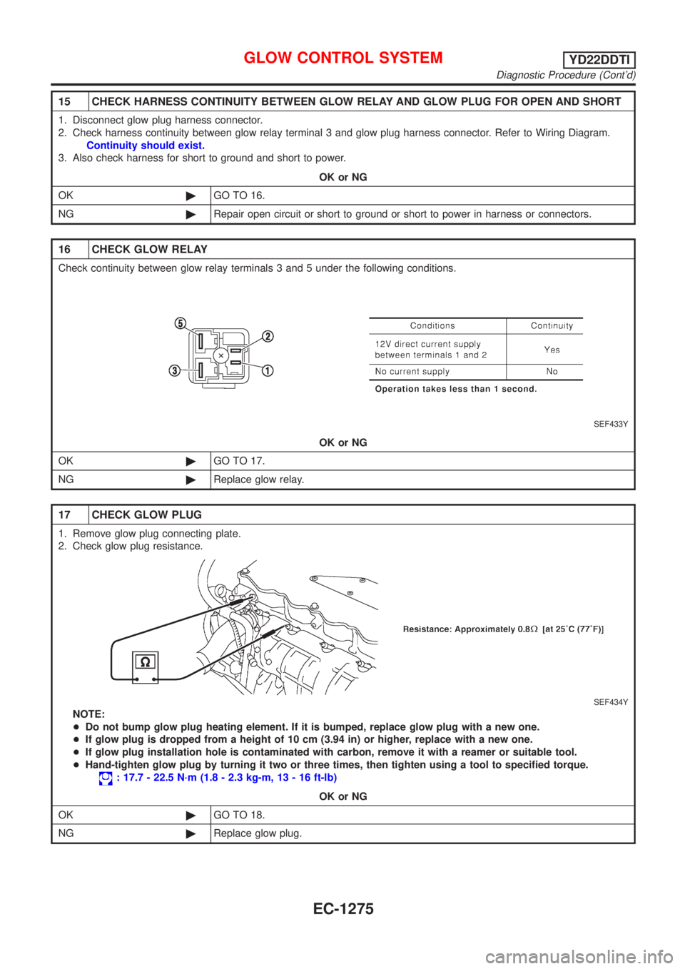
16 CHECK GLOW RELAY
Check continuity between glow relay terminals 3 and 5 under the following conditions.
SEF433Y
OK or NG
OK©GO TO 17.
NG©Replace glow relay.
17 CHECK GLOW PLUG
1. Remove glow plug connecting plate.
2. Check glow plug resistance.
SEF434Y
NOTE:
+Do not bump glow plug heating element. If it is bumped, replace glow plug with a new one.
+If glow plug is dropped from a height of 10 cm (3.94 in) or higher, replace with a new one.
+If glow plug installation hole is contaminated with carbon, remove it with a reamer or suitable tool.
+Hand-tighten glow plug by turning it two or three times, then tighten using a tool to specified torque.
: 17.7 - 22.5 N´m (1.8 - 2.3 kg-m, 13 - 16 ft-lb)
OK or NG
OK©GO TO 18.
NG©Replace glow plug.
GLOW CONTROL SYSTEMYD22DDTI
Diagnostic Procedure (Cont'd)
EC-1275
Page 1704 of 3051
Wiring Diagram=NLEC0767MODELS WITH ECM IN ENGINE COMPARTMENTNLEC0767S01
YEC732
EGR VOLUME CONTROL SYSTEMYD22DDTI
Wiring Diagram
EC-1279
Page 1705 of 3051
MODELS WITH ECM IN CABINNLEC0767S02
YEC866
EGR VOLUME CONTROL SYSTEMYD22DDTI
Wiring Diagram (Cont'd)
EC-1280
Page 1707 of 3051

3 CHECK EGR VOLUME CONTROL VALVE POWER SUPPLY CIRCUIT-II
1. Turn ignition switch ªOFFº.
2. Disconnect ECM relay. (For ECM relay location, refer to ªEngine control component parts locationº, EC-1071.)
3. Check harness continuity between ECM relay terminal 5 and EGR volume control valve terminals 2 and 5. Refer to
Wiring Diagram.
Continuity should exist.
OK or NG
OK©GO TO 4.
NG©Repair open circuit or short to ground or short to power in harness or connectors.
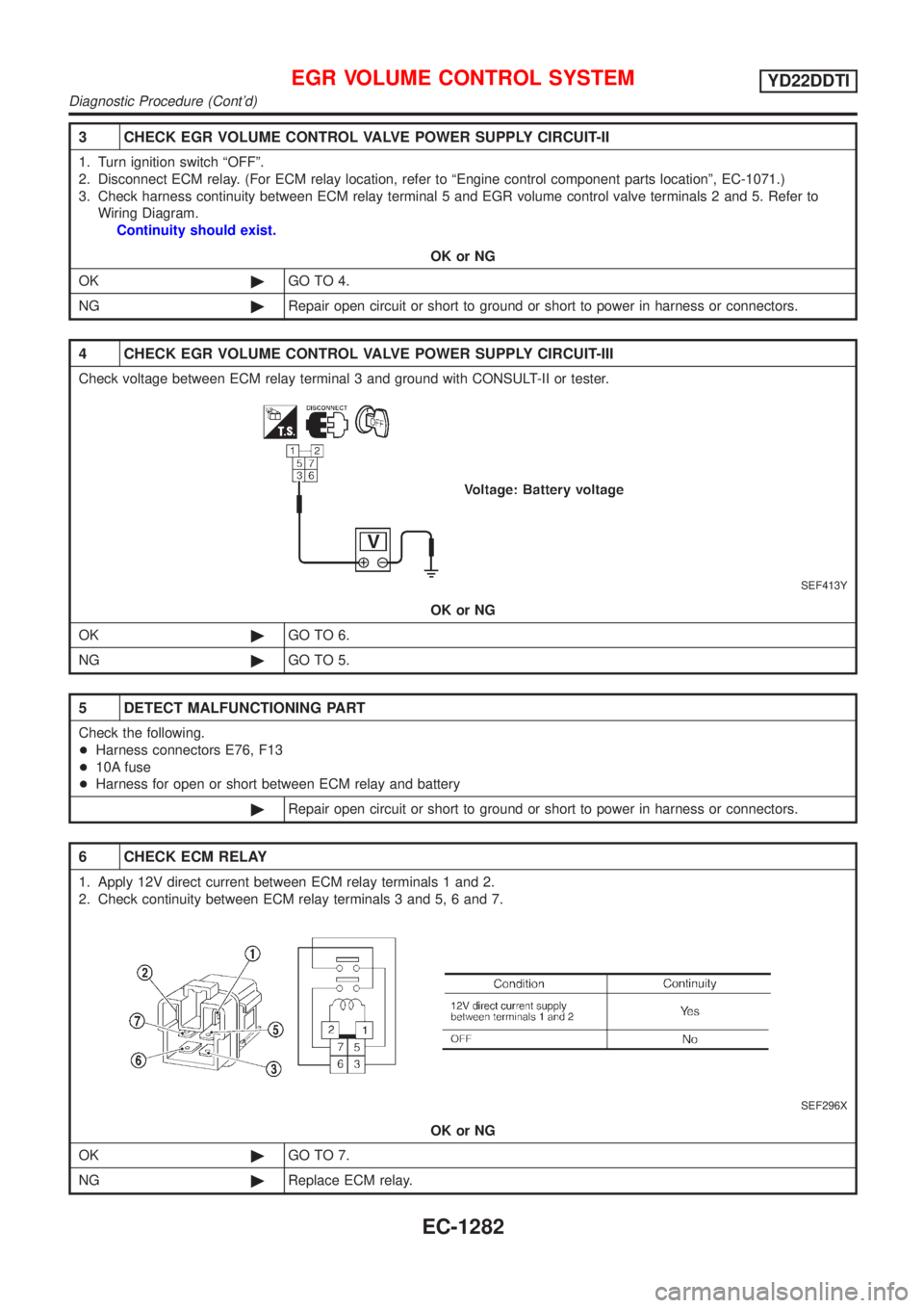
4 CHECK EGR VOLUME CONTROL VALVE POWER SUPPLY CIRCUIT-III
Check voltage between ECM relay terminal 3 and ground with CONSULT-II or tester.
SEF413Y
OK or NG
OK©GO TO 6.
NG©GO TO 5.
5 DETECT MALFUNCTIONING PART
Check the following.
+Harness connectors E76, F13
+10A fuse
+Harness for open or short between ECM relay and battery
©Repair open circuit or short to ground or short to power in harness or connectors.
6 CHECK ECM RELAY
1. Apply 12V direct current between ECM relay terminals 1 and 2.
2. Check continuity between ECM relay terminals 3 and 5, 6 and 7.
SEF296X
OK or NG
OK©GO TO 7.
NG©Replace ECM relay.
EGR VOLUME CONTROL SYSTEMYD22DDTI
Diagnostic Procedure (Cont'd)
EC-1282
Page 1708 of 3051
7 CHECK EGR VOLUME CONTROL VALVE OUTPUT SIGNAL CIRCUIT FOR OPEN AND SHORT
1. Turn ignition switch ªOFFº.
2. Disconnect ECM harness connector.
3. Check harness continuity between ECM terminals and EGR volume control valve terminals as follows.
Refer to Wiring Diagram.
MTBL0463
Continuity should exist.
4. Also check harness for short to ground and short to power.
OK or NG
OK©GO TO 8.
NG©Repair open circuit or short to ground or short to power in harness or connectors.
8 CHECK EGR VOLUME CONTROL VALVE-I
Check resistance between EGR volume control valve terminal 2 and terminals 1, 3, terminal 5 and terminals 4, 6.
SEF414Y
OK or NG
OK (With CONSULT-II)©GO TO 9.
OK (Without CONSULT-
II)©GO TO 10.
NG©Replace EGR volume control valve.
EGR VOLUME CONTROL SYSTEMYD22DDTI
Diagnostic Procedure (Cont'd)
EC-1283
Page 1712 of 3051
Wiring DiagramNLEC1269MODELS WITH ECM IN ENGINE COMPARTMENTNLEC1269S01
YEC737
SWIRL CONTROL VALVE CONTROL SOLENOID VALVEYD22DDTI
Wiring Diagram
EC-1287
Page 1713 of 3051
MODELS WITH ECM IN CABINNLEC1269S02
YEC867
SWIRL CONTROL VALVE CONTROL SOLENOID VALVEYD22DDTI
Wiring Diagram (Cont'd)
EC-1288
Page 1716 of 3051

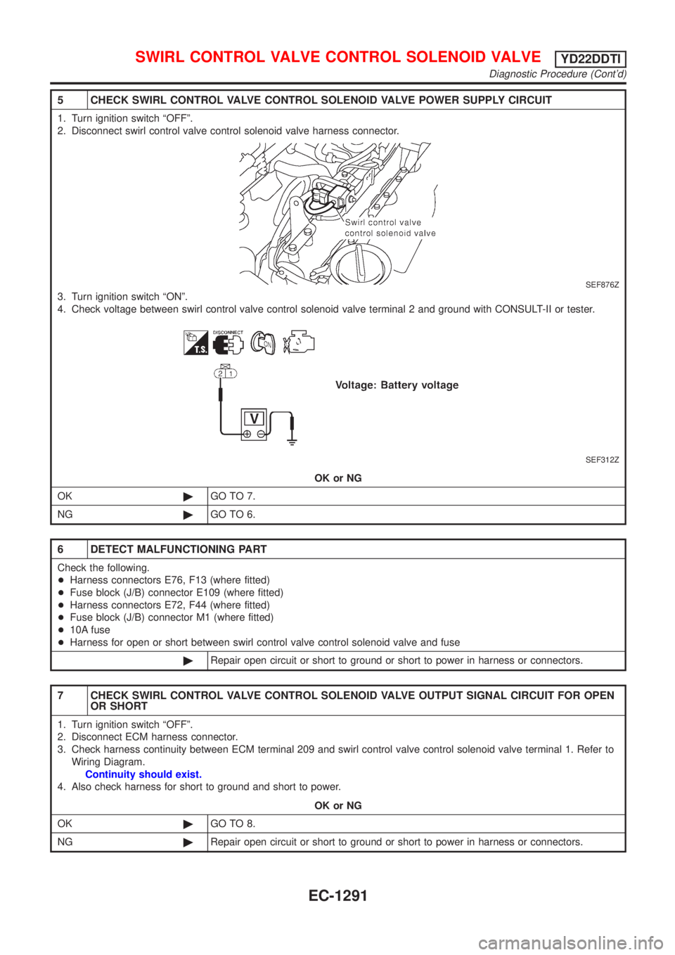
5 CHECK SWIRL CONTROL VALVE CONTROL SOLENOID VALVE POWER SUPPLY CIRCUIT
1. Turn ignition switch ªOFFº.
2. Disconnect swirl control valve control solenoid valve harness connector.
SEF876Z
3. Turn ignition switch ªONº.
4. Check voltage between swirl control valve control solenoid valve terminal 2 and ground with CONSULT-II or tester.
SEF312Z
OK or NG
OK©GO TO 7.
NG©GO TO 6.
6 DETECT MALFUNCTIONING PART
Check the following.
+Harness connectors E76, F13 (where fitted)
+Fuse block (J/B) connector E109 (where fitted)
+Harness connectors E72, F44 (where fitted)
+Fuse block (J/B) connector M1 (where fitted)
+10A fuse
+Harness for open or short between swirl control valve control solenoid valve and fuse
©Repair open circuit or short to ground or short to power in harness or connectors.
7 CHECK SWIRL CONTROL VALVE CONTROL SOLENOID VALVE OUTPUT SIGNAL CIRCUIT FOR OPEN
OR SHORT
1. Turn ignition switch ªOFFº.
2. Disconnect ECM harness connector.
3. Check harness continuity between ECM terminal 209 and swirl control valve control solenoid valve terminal 1. Refer to
Wiring Diagram.
Continuity should exist.
4. Also check harness for short to ground and short to power.
OK or NG
OK©GO TO 8.
NG©Repair open circuit or short to ground or short to power in harness or connectors.
SWIRL CONTROL VALVE CONTROL SOLENOID VALVEYD22DDTI
Diagnostic Procedure (Cont'd)
EC-1291