Page 218 of 3051
SFA114A
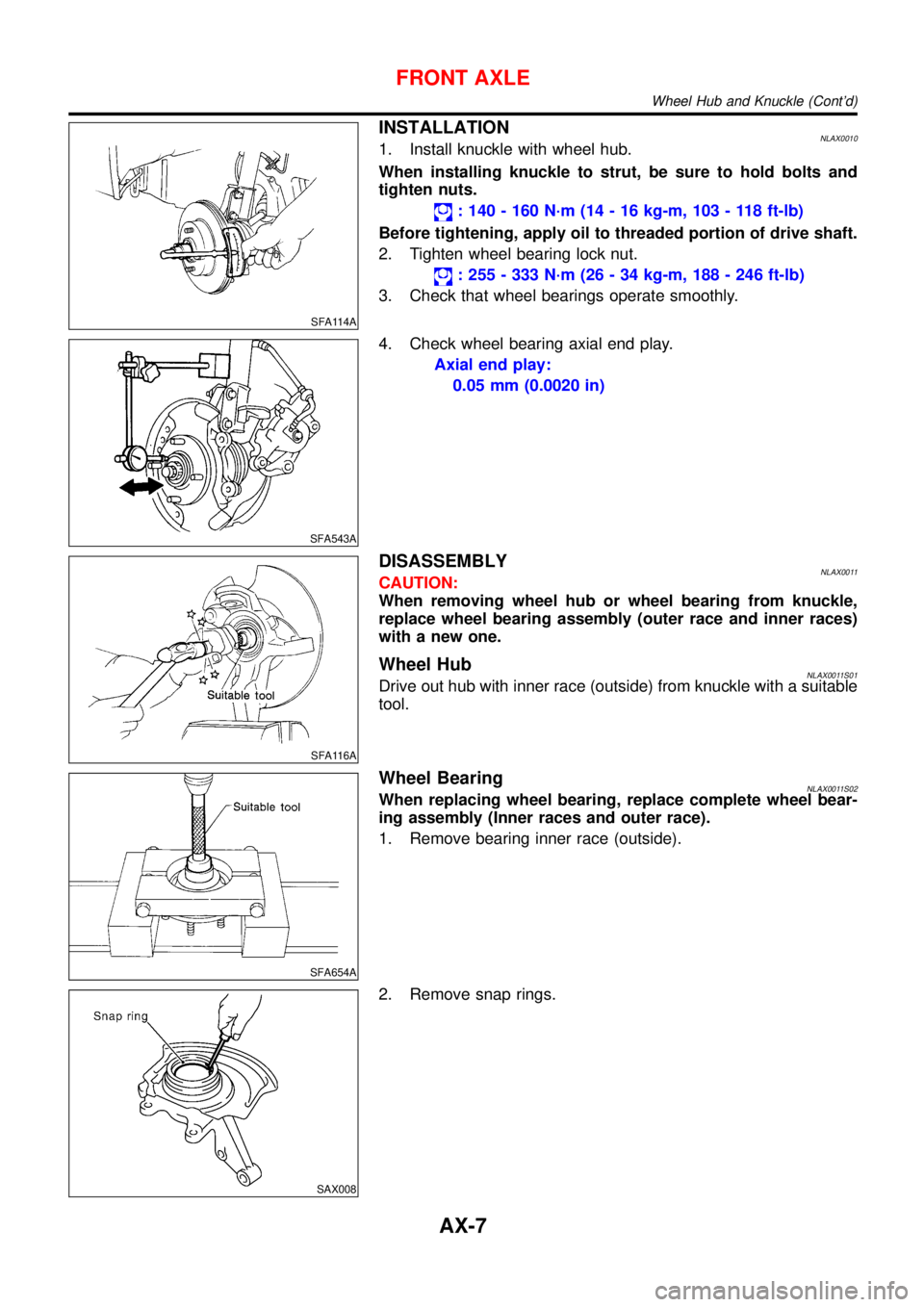
INSTALLATIONNLAX00101. Install knuckle with wheel hub.
When installing knuckle to strut, be sure to hold bolts and
tighten nuts.
: 140 - 160 N·m (14 - 16 kg-m, 103 - 118 ft-lb)
Before tightening, apply oil to threaded portion of drive shaft.
2. Tighten wheel bearing lock nut.
: 255 - 333 N·m (26 - 34 kg-m, 188 - 246 ft-lb)
3. Check that wheel bearings operate smoothly.
SFA543A
4. Check wheel bearing axial end play.
Axial end play:
0.05 mm (0.0020 in)
SFA116A
DISASSEMBLYNLAX0011CAUTION:
When removing wheel hub or wheel bearing from knuckle,
replace wheel bearing assembly (outer race and inner races)
with a new one.
Wheel HubNLAX0011S01Drive out hub with inner race (outside) from knuckle with a suitable
tool.
SFA654A
Wheel BearingNLAX0011S02When replacing wheel bearing, replace complete wheel bear-
ing assembly (Inner races and outer race).
1. Remove bearing inner race (outside).
SAX008
2. Remove snap rings.
FRONT AXLE
Wheel Hub and Knuckle (Cont’d)
AX-7
Page 222 of 3051
SFA090A
REMOVALNLAX00141. Remove wheel bearing lock nut.
Brake caliper need not be disconnected. Do not twist or
stretch brake hose when moving components.
SFA153B
2. Remove strut lower mount bolts.
3. Remove brake hose clip.
SFA499A
4. Separate drive shaft from knuckle by lightly tapping it. If it is
hard to remove, use a puller.
Cover boots with shop towel so as not to damage them
when removing drive shaft.
Refer to“Wheel Hub and Knuckle”,“FRONT AXLE”, AX-5.
5. Remove right drive shaft from transaxle.
NAX004
6. Remove left drive shaft from transaxle.
+Pry off drive shaft from transaxle as shown at left.
SFA482-D
INSTALLATIONNLAX0015Transaxle SideNLAX0015S011. Drive a new oil seal to transaxle. Refer to MT-15 or AT-204,
“Replacing Oil Seal”or“Differential Side Oil Seal
Replacement”,“ON-VEHICLE SERVICE”.
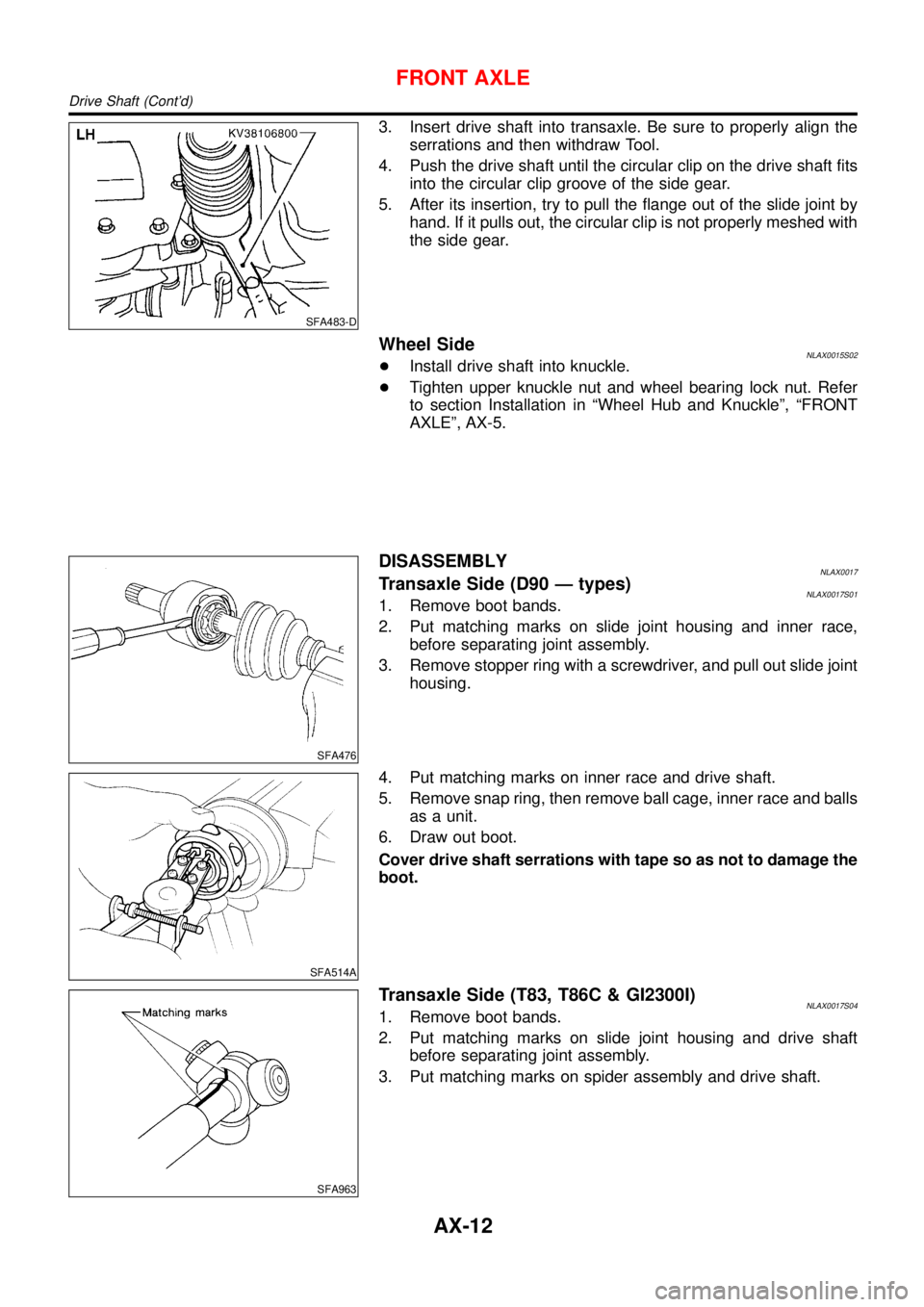
2. Set Tool along the inner circumference of oil seal.
FRONT AXLE
Drive Shaft (Cont’d)
AX-11
Page 223 of 3051
SFA483-D
3. Insert drive shaft into transaxle. Be sure to properly align the
serrations and then withdraw Tool.
4. Push the drive shaft until the circular clip on the drive shaft fits
into the circular clip groove of the side gear.
5. After its insertion, try to pull the flange out of the slide joint by
hand. If it pulls out, the circular clip is not properly meshed with
the side gear.
Wheel SideNLAX0015S02+Install drive shaft into knuckle.
+Tighten upper knuckle nut and wheel bearing lock nut. Refer
to section Installation in“Wheel Hub and Knuckle”,“FRONT
AXLE”, AX-5.
SFA476
DISASSEMBLYNLAX0017Transaxle Side (D90—types)NLAX0017S011. Remove boot bands.
2. Put matching marks on slide joint housing and inner race,
before separating joint assembly.
3. Remove stopper ring with a screwdriver, and pull out slide joint
housing.
SFA514A
4. Put matching marks on inner race and drive shaft.
5. Remove snap ring, then remove ball cage, inner race and balls
as a unit.
6. Draw out boot.
Cover drive shaft serrations with tape so as not to damage the
boot.
SFA963
Transaxle Side (T83, T86C & GI2300I)NLAX0017S041. Remove boot bands.
2. Put matching marks on slide joint housing and drive shaft
before separating joint assembly.
3. Put matching marks on spider assembly and drive shaft.
FRONT AXLE
Drive Shaft (Cont’d)
AX-12
Page 226 of 3051
+Use grease according to AX-19, SDS.
SFA800
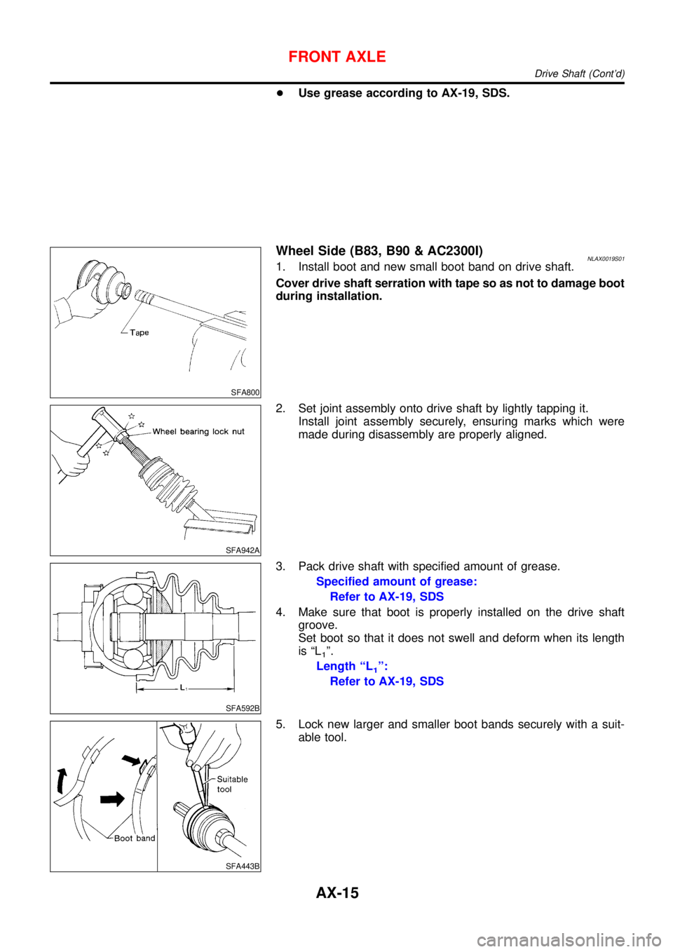
Wheel Side (B83, B90 & AC2300I)NLAX0019S011. Install boot and new small boot band on drive shaft.
Cover drive shaft serration with tape so as not to damage boot
during installation.
SFA942A
2. Set joint assembly onto drive shaft by lightly tapping it.
Install joint assembly securely, ensuring marks which were
made during disassembly are properly aligned.
SFA592B
3. Pack drive shaft with specified amount of grease.
Specified amount of grease:
Refer to AX-19, SDS
4. Make sure that boot is properly installed on the drive shaft
groove.
Set boot so that it does not swell and deform when its length
is“L
1”.
Length“L
1”:
Refer to AX-19, SDS
SFA443B
5. Lock new larger and smaller boot bands securely with a suit-
able tool.
FRONT AXLE
Drive Shaft (Cont’d)
AX-15
Page 227 of 3051
SFA313B
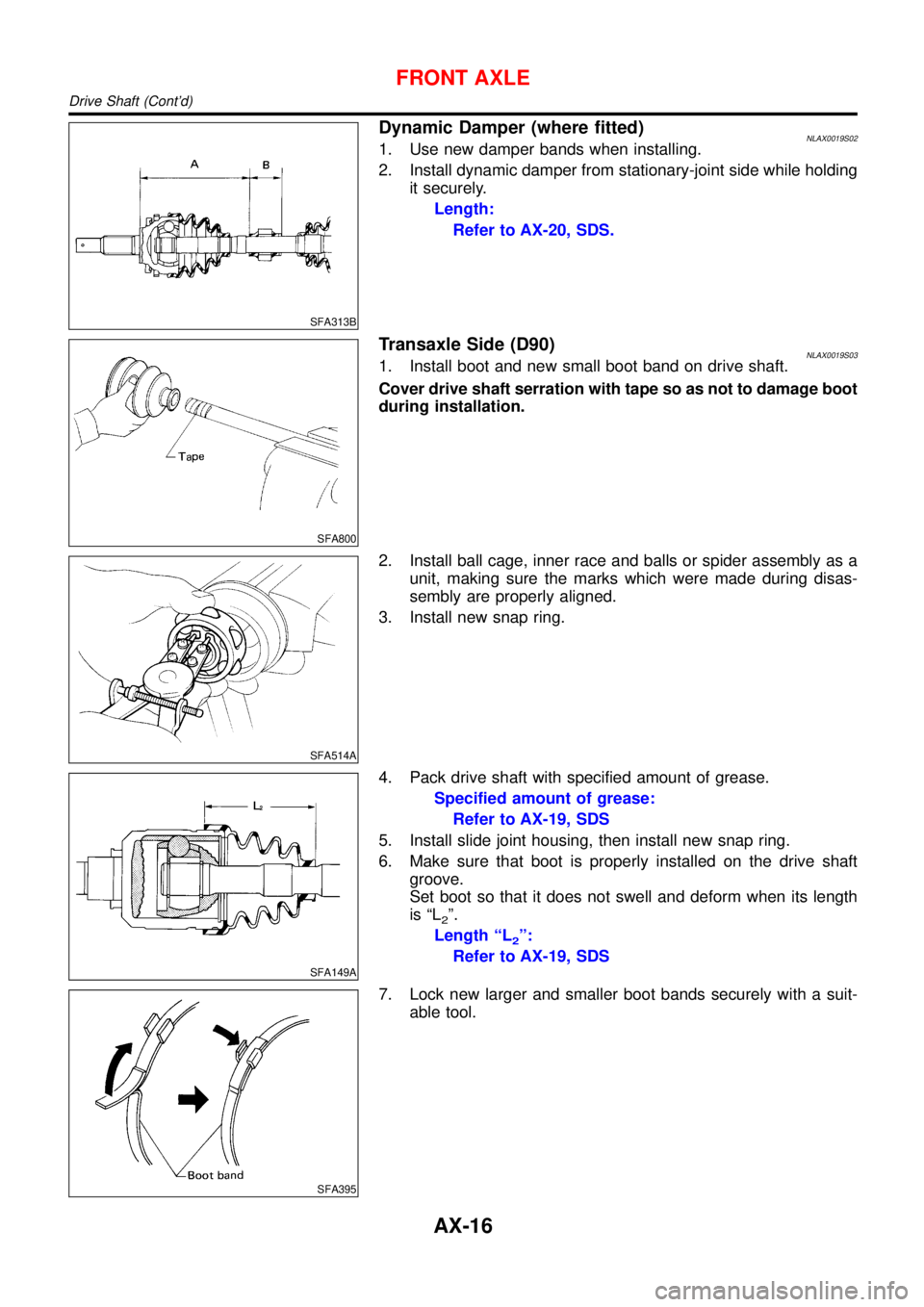
Dynamic Damper (where fitted)NLAX0019S021. Use new damper bands when installing.
2. Install dynamic damper from stationary-joint side while holding
it securely.
Length:
Refer to AX-20, SDS.
SFA800
Transaxle Side (D90)NLAX0019S031. Install boot and new small boot band on drive shaft.
Cover drive shaft serration with tape so as not to damage boot
during installation.
SFA514A
2. Install ball cage, inner race and balls or spider assembly as a
unit, making sure the marks which were made during disas-
sembly are properly aligned.
3. Install new snap ring.
SFA149A
4. Pack drive shaft with specified amount of grease.
Specified amount of grease:
Refer to AX-19, SDS
5. Install slide joint housing, then install new snap ring.
6. Make sure that boot is properly installed on the drive shaft
groove.
Set boot so that it does not swell and deform when its length
is“L
2”.
Length“L
2”:
Refer to AX-19, SDS
SFA395
7. Lock new larger and smaller boot bands securely with a suit-
able tool.
FRONT AXLE
Drive Shaft (Cont’d)
AX-16
Page 228 of 3051
SFA800
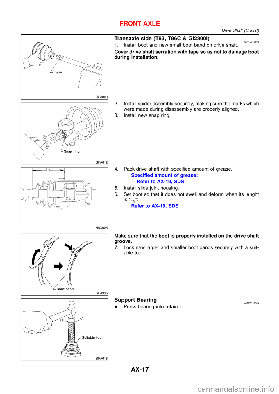
Transaxle side (T83, T86C & GI2300I)NLAX0019S051. Install boot and new small boot band on drive shaft.
Cover drive shaft serration with tape so as not to damage boot
during installation.
SFA612
2. Install spider assembly securely, making sure the marks which
were made during disassembly are properly aligned.
3. Install new snap ring.
NAX005
4. Pack drive shaft with specified amount of grease.
Specified amount of grease:
Refer to AX-19, SDS
5. Install slide joint housing.
6. Set boot so that it does not swell and deform when its lenght
is“L
2”:
Refer to AX-19, SDS
SFA395
Make sure that the boot is properly installed on the drive shaft
groove.
7. Lock new larger and smaller boot bands securely with a suit-
able tool.
SFA618
Support BearingNLAX0019S04+Press bearing into retainer.
FRONT AXLE
Drive Shaft (Cont’d)
AX-17
Page 231 of 3051
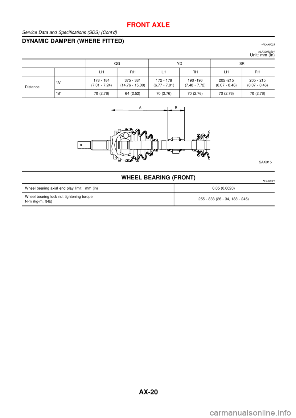
DYNAMIC DAMPER (WHERE FITTED)=NLAX0033
NLAX0033S01
Unit: mm (in)
QG YD SR
LH RH LH RH LH RH
Distance“A”178 - 184
(7.01 - 7.24)375 - 381
(14.76 - 15.00)172 - 178
(6.77 - 7.01)190 -196
(7.48 - 7.72)205 -215
(8.07 - 8.46)205 - 215
(8.07 - 8.46)
“B”70 (2.76) 64 (2.52) 70 (2.76) 70 (2.76) 70 (2.76) 70 (2.76)
SAX015
WHEEL BEARING (FRONT)NLAX0021
Wheel bearing axial end play limit mm (in) 0.05 (0.0020)
Wheel bearing lock nut tightening torque
N·m (kg-m, ft-lb)255 - 333 (26 - 34, 188 - 245)
FRONT AXLE
Service Data and Specifications (SDS) (Cont’d)
AX-20
Page 233 of 3051
Noise, Vibration and Harshness (NVH)
Troubleshooting
NLAX0025Refer to“Noise, Vibration and Harshness (NVH) Troubleshooting”,
“FRONT AXLE”, AX-3.
SMA525A
On-vehicle Service
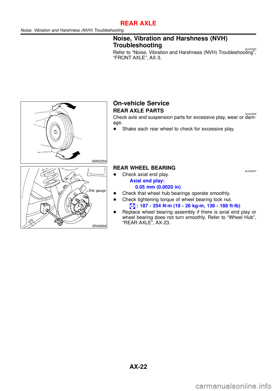
REAR AXLE PARTSNLAX0026Check axle and suspension parts for excessive play, wear or dam-
age.
+Shake each rear wheel to check for excessive play.
SRA690A
REAR WHEEL BEARINGNLAX0027+Check axial end play.
Axial end play:
0.05 mm (0.0020 in)
+Check that wheel hub bearings operate smoothly.
+Check tightening torque of wheel bearing lock nut.
: 187 - 254 N·m (19 - 26 kg-m, 138 - 188 ft-lb)
+Replace wheel bearing assembly if there is axial end play or
wheel bearing does not turn smoothly. Refer to“Wheel Hub”,
“REAR AXLE”, AX-23.
REAR AXLE
Noise, Vibration and Harshness (NVH) Troubleshooting
AX-22