Page 905 of 3051
7 CHECK VALVE TIMING CONTROL SOLENOID VALVE
Refer to ªComponent Inspectionº, EC-480.
OK or NG
OK©GO TO 8.
NG©Replace valve timing control solenoid valve.
8 CHECK INTERMITTENT INCIDENT
Perform ªTROUBLE DIAGNOSIS FOR INTERMITTENT INCIDENTº, EC-145.
©INSPECTION END
SEF159Y
Component InspectionNLEC1321INTAKE VALVE TIMING CONTROL SOLENOID VALVENLEC1321S011. Check oil passage visually for any metal debris.
2. Supply intake valve timing control solenoid valve terminals with
battery voltage.
3. Make sure that inside plunger protrudes.
If NG, replace intake valve timing control solenoid valve.
INTAKE VALVE TIMING CONTROL SOLENOID VALVEQG18DE
Diagnostic Procedure (Cont'd)
EC-480
Page 930 of 3051
Diagnostic ProcedureNLEC0579
1 CHECK ENGINE START
Turn ignition switch ªOFFº, and restart engine.
Is engine running?
YesorNo
Yes (With CONSULT-II)©GO TO 2.
Yes (Without CONSULT-
II)©GO TO 12.
No©GO TO 3.
2 SEARCH FOR MALFUNCTIONING CIRCUIT
With CONSULT-II
1. Perform ªPOWER BALANCEº in ªACTIVE TESTº mode with CONSULT-II.
2. Search for circuit which does not produce a momentary engine speed drop.
SEF190Y
©GO TO 12.
3 CHECK IGNITION COIL POWER SUPPLY CIRCUIT-I
1. Turn ignition switch ON.
2. Check voltage between ECM terminals 110, 112 and ground with CONSULT-II or tester.
SEF366X
OK or NG
OK©GO TO 4.
NG©GO TO TROUBLE DIAGNOSIS FOR POWER SUPPLY, EC-146.
IGNITION SIGNALQG18DE
Diagnostic Procedure
EC-505
Page 931 of 3051
4 CHECK IGNITION COIL POWER SUPPLY CIRCUIT-II
1. Turn ignition switch OFF.
2. Disconnect condenser harness connector.
SEF635Z
3. Turn ignition switch ON.
4. Check voltage between condenser terminal 1 and ground with CONSULT-II or tester.
SEF367X
OK or NG
OK©GO TO 10.
NG©GO TO 5.
5 CHECK IGNITION COIL POWER SUPPLY CIRCUIT-III
1. Turn ignition switch OFF.
2. Disconnect ECM relay. (For ECM relay location, refer to ªEngine Control Compartment Parts Locationº.)
3. Check harness continuity between ECM relay terminal 7 and condenser terminal 1. Refer to Wiring Diagram.
Continuity should exist.
4. Also check harness for short to ground and short to power.
OK or NG
OK©GO TO 7.
NG©GO TO 6.
6 DETECT MALFUNCTIONING PART
Check the harness for open or short between ECM relay and condenser.
©Repair open circuit or short to ground or short to power in harness or connectors.
IGNITION SIGNALQG18DE
Diagnostic Procedure (Cont'd)
EC-506
Page 932 of 3051

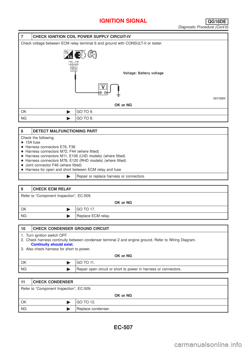
7 CHECK IGNITION COIL POWER SUPPLY CIRCUIT-IV
Check voltage between ECM relay terminal 6 and ground with CONSULT-II or tester.
SEF368X
OK or NG
OK©GO TO 9.
NG©GO TO 8.
8 DETECT MALFUNCTIONING PART
Check the following.
+15A fuse
+Harness connectors E76, F36
+Harness connectors M72, F44 (where fitted)
+Harness connectors M11, E106 (LHD models) (where fitted)
+Harness connectors M78, E120 (RHD models) (where fitted)
+Joint connector F46 (where fitted)
+Harness for open and short between ECM relay and fuse
©Repair or replace harness or connectors.
9 CHECK ECM RELAY
Refer to ªComponent Inspectionº, EC-509.
OK or NG
OK©GO TO 17.
NG©Replace ECM relay.
10 CHECK CONDENSER GROUND CIRCUIT
1. Turn ignition switch OFF.
2. Check harness continuity between condenser terminal 2 and engine ground. Refer to Wiring Diagram.
Continuity should exist.
3. Also check harness for short to power.
OK or NG
OK©GO TO 11.
NG©Repair open circuit or short to power in harness or connectors.
11 CHECK CONDENSER
Refer to ªComponent Inspectionº, EC-509.
OK or NG
OK©GO TO 12.
NG©Replace condenser.
IGNITION SIGNALQG18DE
Diagnostic Procedure (Cont'd)
EC-507
Page 933 of 3051
12 CHECK IGNITION COIL POWER SUPPLY CIRCUIT-V
1. Turn ignition switch OFF.
2. Reconnect harness connectors disconnected.
3. Disconnect ignition coil harness connector.
JEF119Y
4. Turn ignition switch ON.
5. Check voltage between ignition coil terminal 1 and ground with CONSULT-II or tester.
SEF122Y
OK or NG
OK©GO TO 14.
NG©GO TO 13.
13 DETECT MALFUNCTIONING PART
Check the harness for open or short between ignition coil and ECM relay terminal 7.
©Repair or replace harness or connectors.
14 CHECK IGNITION COIL GROUND CIRCUIT
1. Turn ignition switch OFF.
2. Check harness continuity between ignition coil terminal 2 and engine ground. Refer to Wiring Diagram.
Continuity should exist.
3. Also check harness for short to power.
OK or NG
OK©GO TO 15.
NG©Repair open circuit or short to power in harness or connectors.
IGNITION SIGNALQG18DE
Diagnostic Procedure (Cont'd)
EC-508
Page 934 of 3051

15 CHECK IGNITION COIL OUTPUT SIGNAL CIRCUIT
1. Disconnect ECM harness connector.
2. Check harness continuity between ECM terminals 35, 36, 37, 38 and ignition coil terminal 3. Refer to Wiring Diagram.
Continuity should exist.
3. Also check harness for short to ground and short to power.
OK or NG
OK©GO TO 16.
NG©Repair open circuit or short to ground or short to power in harness or connectors.
16 CHECK IGNITION COIL WITH POWER TRANSISTOR
Refer to ªComponent Inspectionº, EC-509.
OK or NG
OK©GO TO 17.
NG©Replace ignition coil with power transistor.
17 CHECK INTERMITTENT INCIDENT
Refer to ªTROUBLE DIAGNOSIS FOR INTERMITTENT INCIDENTº, EC-145.
©INSPECTION END
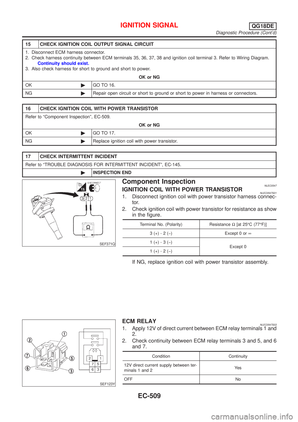
SEF371Q
Component InspectionNLEC0547IGNITION COIL WITH POWER TRANSISTORNLEC0547S011. Disconnect ignition coil with power transistor harness connec-
tor.
2. Check ignition coil with power transistor for resistance as show
in the figure.
Terminal No. (Polarity) ResistanceW[at 25ÉC (77ÉF)]
3 (+) - 2 (þ) Except 0 or¥
1 (+) - 3 (þ)
Except 0
1 (+) - 2 (þ)
If NG, replace ignition coil with power transistor assembly.
SEF123Y
ECM RELAYNLEC0547S031. Apply 12V of direct current between ECM relay terminals 1 and
2.
2. Check continuity between ECM relay terminals 3 and 5, and 6
and 7.
Condition Continuity
12V direct current supply between ter-
minals 1 and 2Ye s
OFF No
IGNITION SIGNALQG18DE
Diagnostic Procedure (Cont'd)
EC-509
Page 951 of 3051
Diagnostic Procedure=NLEC0454
1 INSPECTION START
Do you have CONSULT-II?
YesorNo
Ye s©GO TO 2.
No©GO TO 3.
2 CHECK OVERALL FUNCTION
With CONSULT-II
1. Start engine.
2. Check ªPW/ST SIGNALº in ªDATA MONITORº mode with CONSULT-II under the following conditions.
SEF311Y
OK or NG
OK©INSPECTION END
NG©GO TO 4.
3 CHECK OVERALL FUNCTION
Without CONSULT-II
1. Start engine.
2. Check voltage between ECM terminal 46 and ground under the following conditions.
SEF614Y
OK or NG
OK©INSPECTION END
NG©GO TO 4.
POWER STEERING OIL PRESSURE SWITCHQG18DE
Diagnostic Procedure
EC-526
Page 952 of 3051

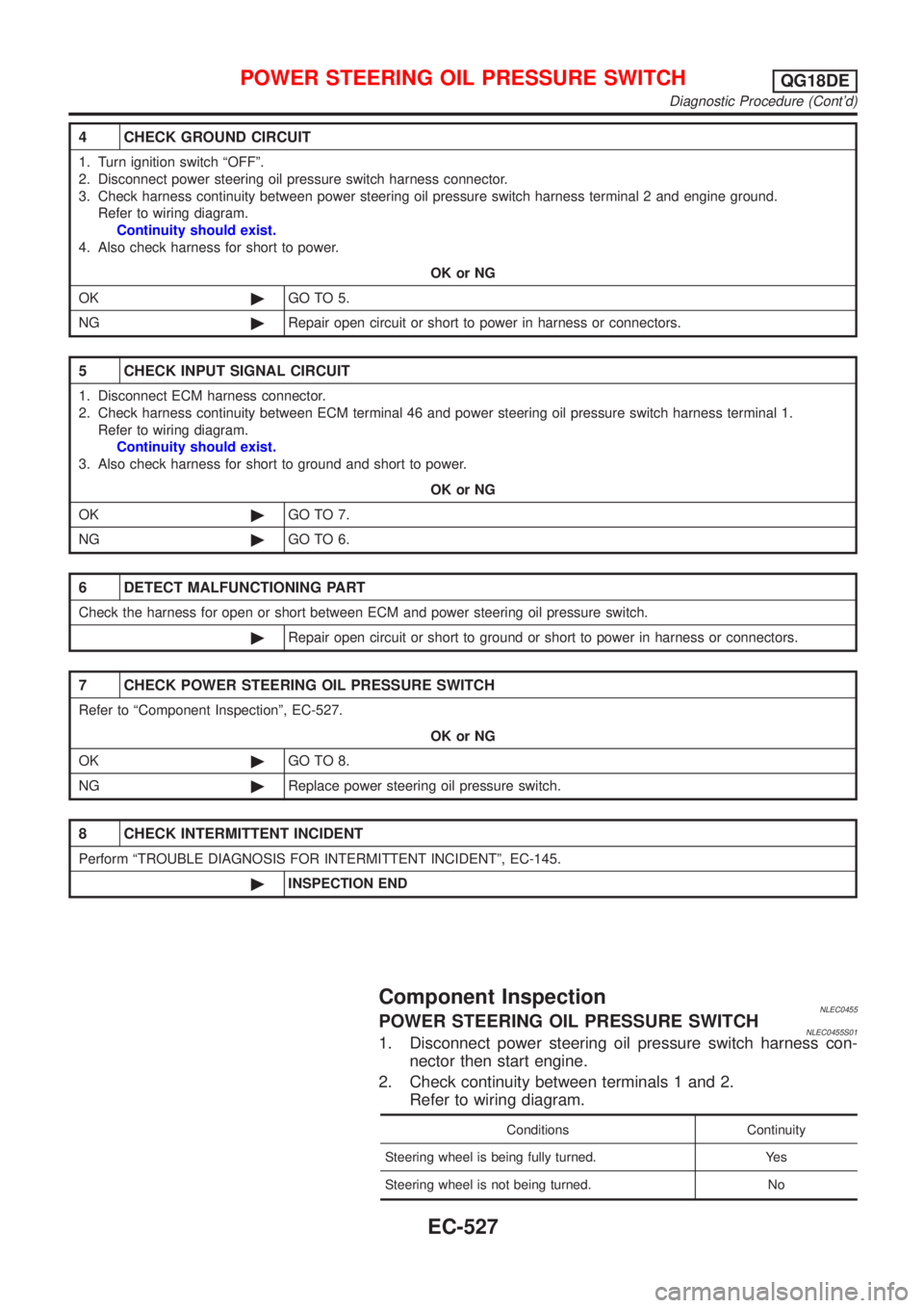
4 CHECK GROUND CIRCUIT
1. Turn ignition switch ªOFFº.
2. Disconnect power steering oil pressure switch harness connector.
3. Check harness continuity between power steering oil pressure switch harness terminal 2 and engine ground.
Refer to wiring diagram.
Continuity should exist.
4. Also check harness for short to power.
OK or NG
OK©GO TO 5.
NG©Repair open circuit or short to power in harness or connectors.
5 CHECK INPUT SIGNAL CIRCUIT
1. Disconnect ECM harness connector.
2. Check harness continuity between ECM terminal 46 and power steering oil pressure switch harness terminal 1.
Refer to wiring diagram.
Continuity should exist.
3. Also check harness for short to ground and short to power.
OK or NG
OK©GO TO 7.
NG©GO TO 6.
6 DETECT MALFUNCTIONING PART
Check the harness for open or short between ECM and power steering oil pressure switch.
©Repair open circuit or short to ground or short to power in harness or connectors.
7 CHECK POWER STEERING OIL PRESSURE SWITCH
Refer to ªComponent Inspectionº, EC-527.
OK or NG
OK©GO TO 8.
NG©Replace power steering oil pressure switch.
8 CHECK INTERMITTENT INCIDENT
Perform ªTROUBLE DIAGNOSIS FOR INTERMITTENT INCIDENTº, EC-145.
©INSPECTION END
Component InspectionNLEC0455POWER STEERING OIL PRESSURE SWITCHNLEC0455S011. Disconnect power steering oil pressure switch harness con-
nector then start engine.
2. Check continuity between terminals 1 and 2.
Refer to wiring diagram.
Conditions Continuity
Steering wheel is being fully turned. Yes
Steering wheel is not being turned. No
POWER STEERING OIL PRESSURE SWITCHQG18DE
Diagnostic Procedure (Cont'd)
EC-527