Page 262 of 3051
SBR976B
SBR932C
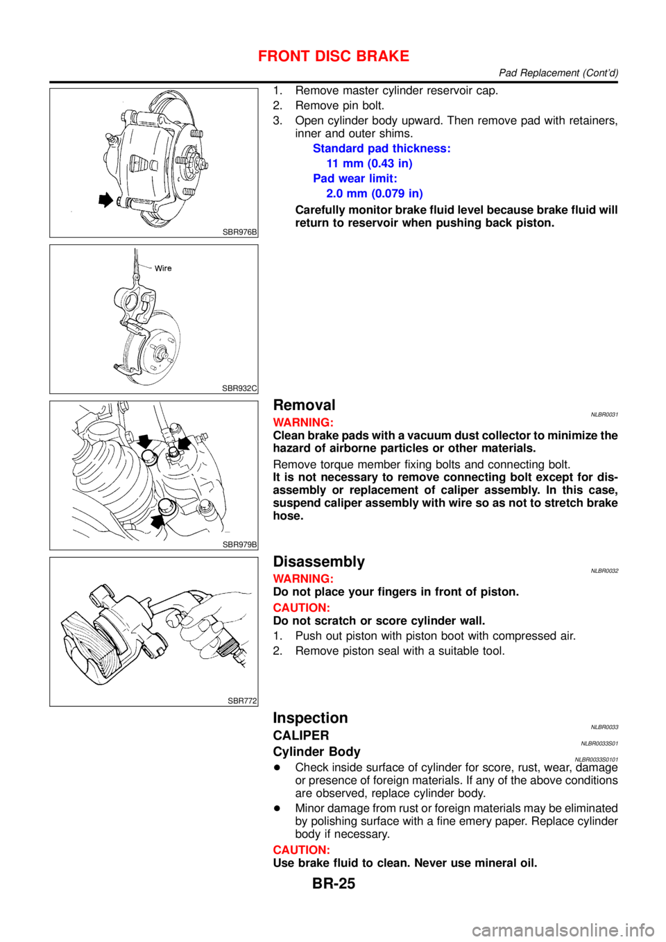
1. Remove master cylinder reservoir cap.
2. Remove pin bolt.
3. Open cylinder body upward. Then remove pad with retainers,
inner and outer shims.
Standard pad thickness:
11 mm (0.43 in)
Pad wear limit:
2.0 mm (0.079 in)
Carefully monitor brake fluid level because brake fluid will
return to reservoir when pushing back piston.
SBR979B
RemovalNLBR0031WARNING:
Clean brake pads with a vacuum dust collector to minimize the
hazard of airborne particles or other materials.
Remove torque member fixing bolts and connecting bolt.
It is not necessary to remove connecting bolt except for dis-
assembly or replacement of caliper assembly. In this case,
suspend caliper assembly with wire so as not to stretch brake
hose.
SBR772
DisassemblyNLBR0032WARNING:
Do not place your fingers in front of piston.
CAUTION:
Do not scratch or score cylinder wall.
1. Push out piston with piston boot with compressed air.
2. Remove piston seal with a suitable tool.
InspectionNLBR0033CALIPERNLBR0033S01Cylinder BodyNLBR0033S0101+Check inside surface of cylinder for score, rust, wear, damage
or presence of foreign materials. If any of the above conditions
are observed, replace cylinder body.
+Minor damage from rust or foreign materials may be eliminated
by polishing surface with a fine emery paper. Replace cylinder
body if necessary.
CAUTION:
Use brake fluid to clean. Never use mineral oil.
FRONT DISC BRAKE
Pad Replacement (Cont’d)
BR-25
Page 268 of 3051
SBR088B
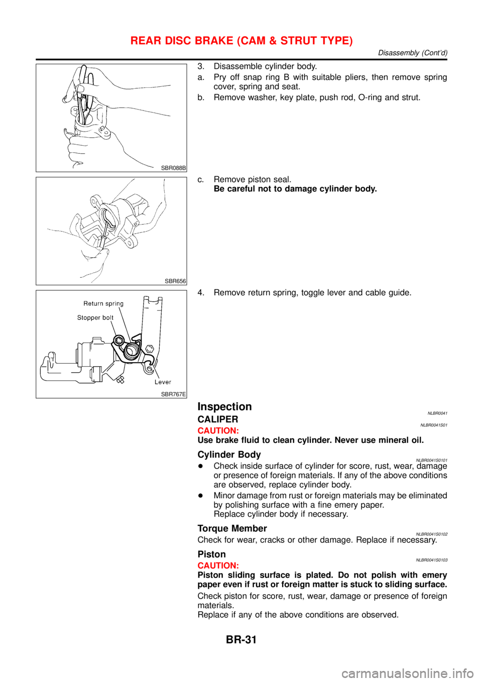
3. Disassemble cylinder body.
a. Pry off snap ring B with suitable pliers, then remove spring
cover, spring and seat.
b. Remove washer, key plate, push rod, O-ring and strut.
SBR656
c. Remove piston seal.
Be careful not to damage cylinder body.
SBR767E
4. Remove return spring, toggle lever and cable guide.
InspectionNLBR0041CALIPERNLBR0041S01CAUTION:
Use brake fluid to clean cylinder. Never use mineral oil.
Cylinder BodyNLBR0041S0101+Check inside surface of cylinder for score, rust, wear, damage
or presence of foreign materials. If any of the above conditions
are observed, replace cylinder body.
+Minor damage from rust or foreign materials may be eliminated
by polishing surface with a fine emery paper.
Replace cylinder body if necessary.
Torque MemberNLBR0041S0102Check for wear, cracks or other damage. Replace if necessary.
PistonNLBR0041S0103CAUTION:
Piston sliding surface is plated. Do not polish with emery
paper even if rust or foreign matter is stuck to sliding surface.
Check piston for score, rust, wear, damage or presence of foreign
materials.
Replace if any of the above conditions are observed.
REAR DISC BRAKE (CAM & STRUT TYPE)
Disassembly (Cont’d)
BR-31
Page 338 of 3051
Removal and InstallationNLBT0004+When removing or installing hood, place a cloth or other padding on hood. This prevents vehicle body from
being scratched.
+Bumper fascia is made of plastic. Do not use excessive force and be sure to keep oil away from it.
+Hood adjustment: Adjust at hinge portion.
+Hood lock adjustment: After adjusting, check hood lock control operation. Apply a coat of grease to hood
locks engaging mechanism.
+Hood opener: Do not attempt to bend cable forcibly. Doing so increases effort required to unlock hood.
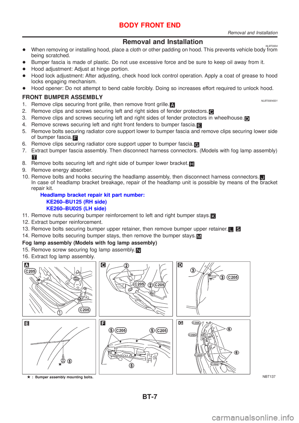
FRONT BUMPER ASSEMBLYNLBT0004S011. Remove clips securing front grille, then remove front grille.
2. Remove clips and screws securing left and right sides of fender protectors.
3. Remove clips and screws securing left and right sides of fender protectors in wheelhouse.
4. Remove screws securing left and right front fenders to bumper fascia.
5. Remove bolts securing radiator core support lower to bumper fascia and remove clips securing lower side
of bumper fascia.
6. Remove clips securing radiator core support upper to bumper fascia.
7. Extract bumper fascia assembly. Then disconnect harness connectors. (Models with fog lamp assembly)
8. Remove bolts securing left and right side of bumper lower bracket.
9. Remove energy absorber.
10. Remove bolts and hooks securing the headlamp assembly, then disconnect harness connectors.
In case of headlamp bracket breakage, repair of the headlamp unit is possible by means of the bracket
repair kit.
Headlamp bracket repair kit part number:
KE260±BU125 (RH side)
KE260±BU025 (LH side)
11. Remove nuts securing bumper reinforcement to left and right bumper stays.
12. Extract bumper reinforcement.
13. Remove bolts securing bumper upper retainer, then remove bumper upper retainer.
14. Remove bolts securing bumper stays, then remove the bumper stays.
Fog lamp assembly (Models with fog lamp assembly)
15. Remove screw securing fog lamp assembly.
16. Extract fog lamp assembly.
NBT137
BODY FRONT END
Removal and Installation
BT-7
Page 341 of 3051
Removal and InstallationNLBT0034+When removing or installing back door, place a cloth or other padding on back door. This prevents vehicle
body from being scratched.
+Bumper fascia is made of plastic. Do not use excessive force and be sure to keep oil away from it.
+Back door adjustment: Adjust at hinge-back door portion for proper back door fit.
+Back door lock system adjustment: Adjust striker so that it is in the center of the lock. After adjustment,
check back door lock operation.
+After installation, make sure that back door and fuel filler lid open smoothly.
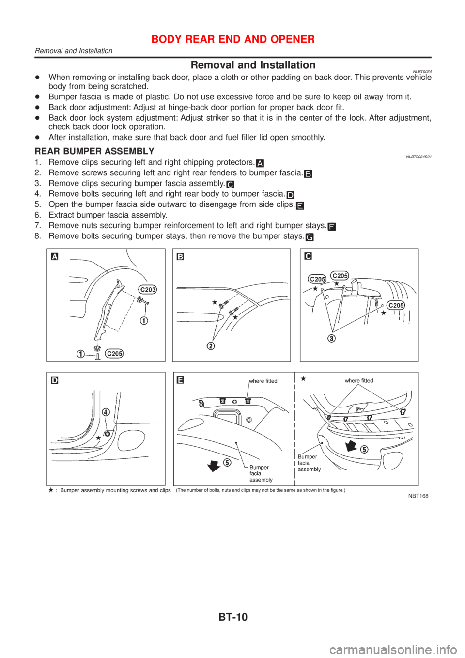
REAR BUMPER ASSEMBLYNLBT0034S011. Remove clips securing left and right chipping protectors.
2. Remove screws securing left and right rear fenders to bumper fascia.
3. Remove clips securing bumper fascia assembly.
4. Remove bolts securing left and right rear body to bumper fascia.
5. Open the bumper fascia side outward to disengage from side clips.
6. Extract bumper fascia assembly.
7. Remove nuts securing bumper reinforcement to left and right bumper stays.
8. Remove bolts securing bumper stays, then remove the bumper stays.
NBT168
BODY REAR END AND OPENER
Removal and Installation
BT-10
Page 423 of 3051
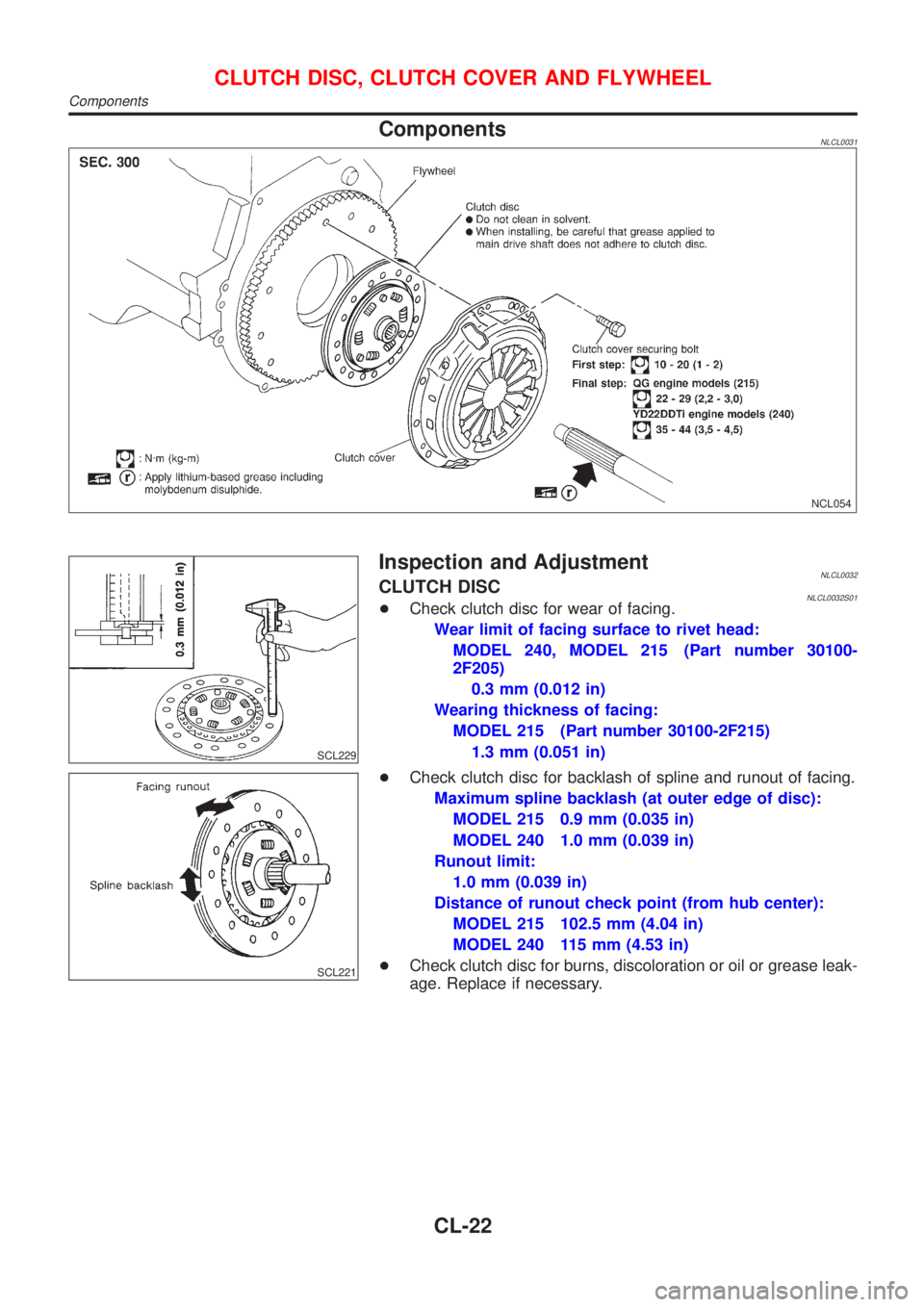
ComponentsNLCL0031
NCL054
SCL229
Inspection and AdjustmentNLCL0032CLUTCH DISCNLCL0032S01+Check clutch disc for wear of facing.
Wear limit of facing surface to rivet head:
MODEL 240, MODEL 215 (Part number 30100-
2F205)
0.3 mm (0.012 in)
Wearing thickness of facing:
MODEL 215 (Part number 30100-2F215)
1.3 mm (0.051 in)
SCL221
+Check clutch disc for backlash of spline and runout of facing.
Maximum spline backlash (at outer edge of disc):
MODEL 215 0.9 mm (0.035 in)
MODEL 240 1.0 mm (0.039 in)
Runout limit:
1.0 mm (0.039 in)
Distance of runout check point (from hub center):
MODEL 215 102.5 mm (4.04 in)
MODEL 240 115 mm (4.53 in)
+Check clutch disc for burns, discoloration or oil or grease leak-
age. Replace if necessary.
CLUTCH DISC, CLUTCH COVER AND FLYWHEEL
Components
CL-22
Page 469 of 3051
If results are unsatisfactory, perform Fuel Pressure Regulator
Check, EC-44.
SEF718B
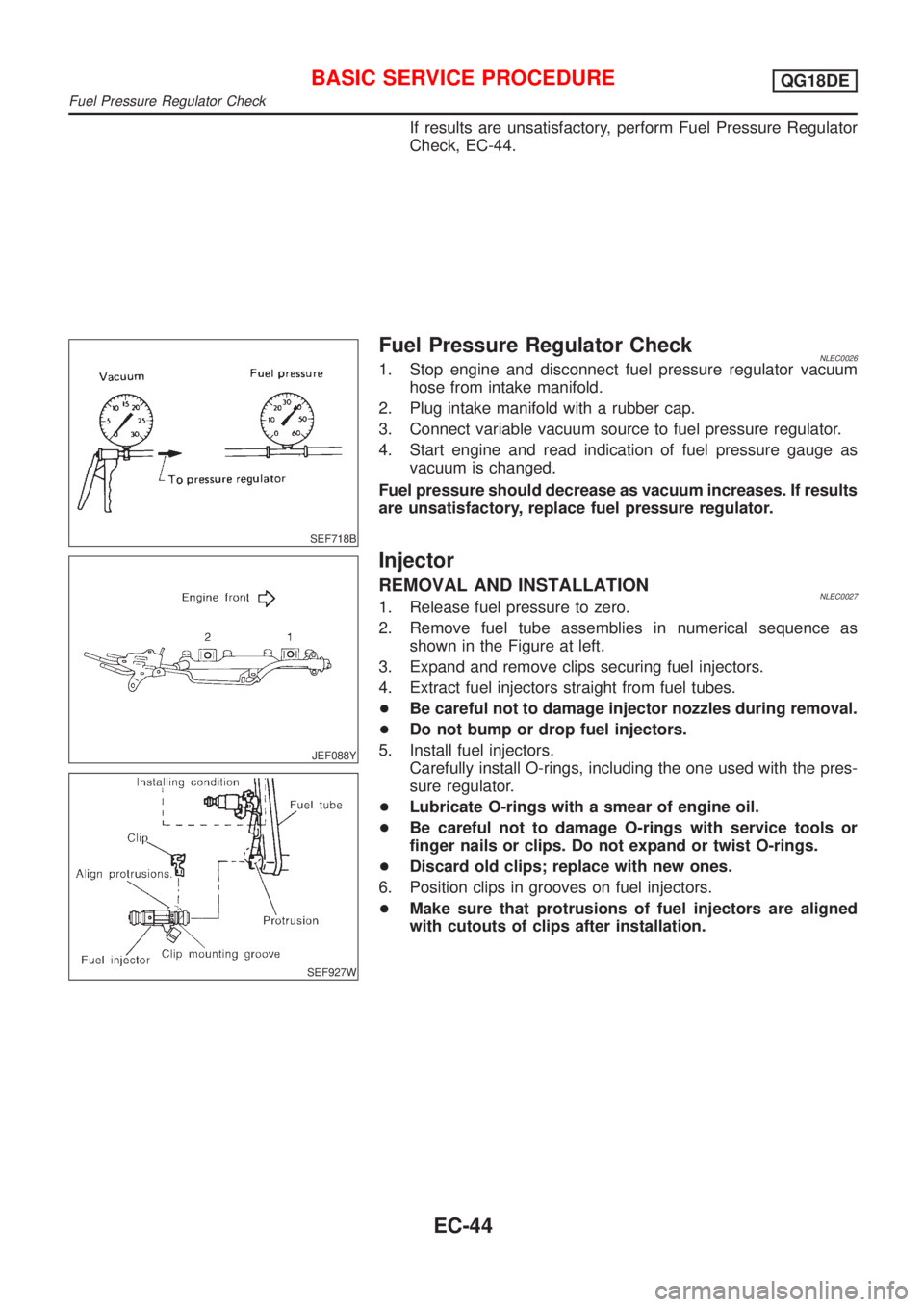
Fuel Pressure Regulator CheckNLEC00261. Stop engine and disconnect fuel pressure regulator vacuum
hose from intake manifold.
2. Plug intake manifold with a rubber cap.
3. Connect variable vacuum source to fuel pressure regulator.
4. Start engine and read indication of fuel pressure gauge as
vacuum is changed.
Fuel pressure should decrease as vacuum increases. If results
are unsatisfactory, replace fuel pressure regulator.
JEF088Y
SEF927W
Injector
REMOVAL AND INSTALLATIONNLEC00271. Release fuel pressure to zero.
2. Remove fuel tube assemblies in numerical sequence as
shown in the Figure at left.
3. Expand and remove clips securing fuel injectors.
4. Extract fuel injectors straight from fuel tubes.
+Be careful not to damage injector nozzles during removal.
+Do not bump or drop fuel injectors.
5. Install fuel injectors.
Carefully install O-rings, including the one used with the pres-
sure regulator.
+Lubricate O-rings with a smear of engine oil.
+Be careful not to damage O-rings with service tools or
finger nails or clips. Do not expand or twist O-rings.
+Discard old clips; replace with new ones.
6. Position clips in grooves on fuel injectors.
+Make sure that protrusions of fuel injectors are aligned
with cutouts of clips after installation.
BASIC SERVICE PROCEDUREQG18DE
Fuel Pressure Regulator Check
EC-44
Page 471 of 3051
SEF058Y
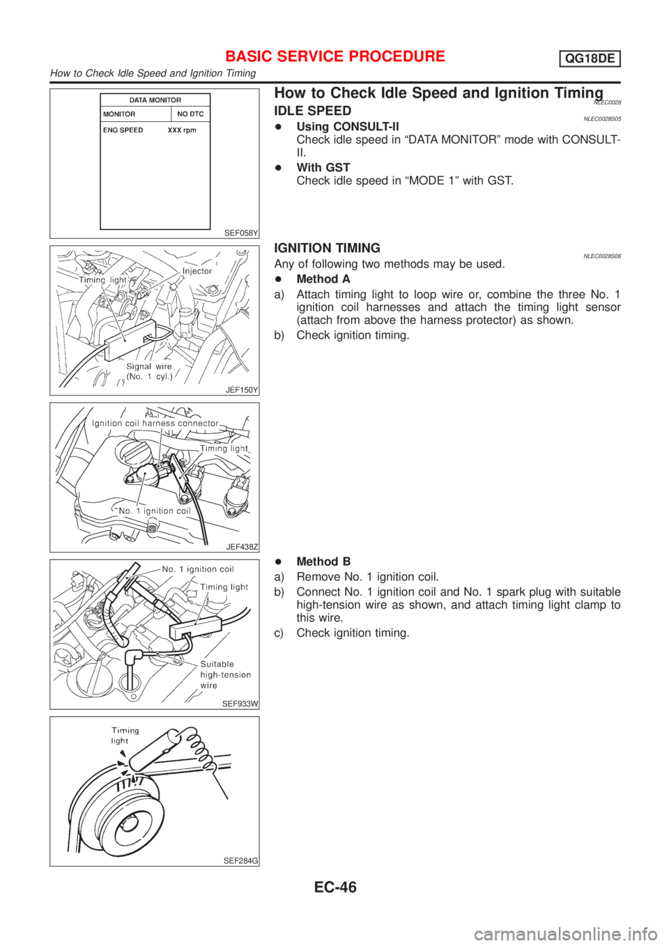
How to Check Idle Speed and Ignition TimingNLEC0028IDLE SPEEDNLEC0028S05+Using CONSULT-II
Check idle speed in ªDATA MONITORº mode with CONSULT-
II.
+With GST
Check idle speed in ªMODE 1º with GST.
JEF150Y
JEF438Z
IGNITION TIMINGNLEC0028S06Any of following two methods may be used.
+Method A
a) Attach timing light to loop wire or, combine the three No. 1
ignition coil harnesses and attach the timing light sensor
(attach from above the harness protector) as shown.
b) Check ignition timing.
SEF933W
SEF284G
+Method B
a) Remove No. 1 ignition coil.
b) Connect No. 1 ignition coil and No. 1 spark plug with suitable
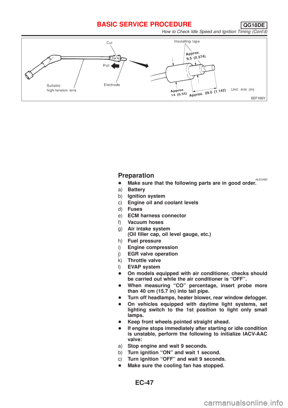
high-tension wire as shown, and attach timing light clamp to
this wire.
c) Check ignition timing.
BASIC SERVICE PROCEDUREQG18DE
How to Check Idle Speed and Ignition Timing
EC-46
Page 472 of 3051
SEF166Y
PreparationNLEC0592+Make sure that the following parts are in good order.
a)Battery
b)Ignition system
c)Engine oil and coolant levels
d)Fuses
e)ECM harness connector
f)Vacuum hoses
g)Air intake system
(Oil filler cap, oil level gauge, etc.)
h)Fuel pressure
i)Engine compression
j)EGR valve operation
k)Throttle valve
l)EVAP system
+On models equipped with air conditioner, checks should
be carried out while the air conditioner is ªOFFº.
+When measuring ªCOº percentage, insert probe more
than 40 cm (15.7 in) into tail pipe.
+Turn off headlamps, heater blower, rear window defogger.
+On vehicles equipped with daytime light systems, set
lighting switch to the 1st position to light only small
lamps.
+Keep front wheels pointed straight ahead.
+If engine stops immediately after starting or idle condition
is unstable, perform the following to initialize IACV-AAC
valve:
a)Stop engine and wait 9 seconds.
b)Turn ignition ªONº and wait 1 second.
c)Turn ignition ªOFFº and wait 9 seconds.
+Make sure the cooling fan has stopped.
BASIC SERVICE PROCEDUREQG18DE
How to Check Idle Speed and Ignition Timing (Cont'd)
EC-47