2001 NISSAN ALMERA TINO maintenance
[x] Cancel search: maintenancePage 2596 of 3051

+When installing an air conditioner in the vehicle, connect the pipes as the final stage of the opera-
tion. Do not remove the seal caps of pipes and other components until just before required for
connection.
+Allow components stored in cool areas to warm to working area temperature before removing seal
caps. This prevents condensation from forming inside A/C components.
+Thoroughly remove moisture from the refrigeration system before charging the refrigerant.
+Always replace used O-rings.
+When connecting tube, apply lubricant to circle of the O-rings shown in illustration. Be careful not
to apply lubricant to threaded portion.
Lubricant name: Nissan A/C System Oil Type R for DKV-11G compressor
Part number: KLH00-PAGR0
Lubricant name: Nissan A/C System Oil Type S for CSV613 compressor
Part number: KLH00-PAGS0
+O-ring must be closely attached to dented portion of tube.
+When replacing the O-ring, be careful not to damage O-ring and tube.
+Connect tube until you hear it click, then tighten the nut or bolt by hand until snug. Make sure that
the O-ring is installed to tube correctly.
+After connecting line, conduct leak test and make sure that there is no leakage from connections.
When the gas leaking point is found, disconnect that line and replace the O-ring. Then tighten
connections of seal seat to the specified torque.
RHA861F
Precautions for Servicing CompressorNLHA0116+Plug all openings to prevent moisture and foreign matter from entering.
+When the compressor is removed, store it in the same position as it is when mounted on the car.
+When replacing or repairing compressor, follow“Maintenance of Lubricant Quantity in Compres-
sor”exactly. Refer to HA-87.
+Keep friction surfaces between clutch and pulley clean. If the surface is contaminated, with
lubricant, wipe it off by using a clean waste cloth moistened with thinner.
+After compressor service operation, turn the compressor shaft by hand more than five turns in
both directions. This will equally distribute lubricant inside the compressor. After the compressor
is installed, let the engine idle and operate the compressor for one hour.
+After replacing the compressor magnet clutch, apply voltage to the new one and check for normal
operation.
PRECAUTIONS
Precautions for Refrigerant Connection (Cont’d)
HA-5
Page 2597 of 3051

Precautions for Service EquipmentNLHA0117RECOVERY/RECYCLING EQUIPMENTNLHA0117S01Follow the manufacturer’s instructions for machine operation and
machine maintenance. Never introduce any refrigerant other than
that specified into the machine.
ELECTRONIC LEAK DETECTORNLHA0117S02Follow the manufacture’s instructions for tester operation and
tester maintenance.
RHA270D
VACUUM PUMPNLHA0117S03The lubricant contained inside the vacuum pump is not compatible
with the specified lubricant for HFC-134a (R-134a) A/C systems.
The vent side of the vacuum pump is exposed to atmospheric
pressure. So the vacuum pump lubricant may migrate out of the
pump into the service hose. This is possible when the pump is
switched off after evacuation (vacuuming) and hose is connected
to it.
To prevent this migration, use a manual valve situated near the
hose-to-pump connection, as follows.
+Usually vacuum pumps have a manual isolator valve as part
of the pump. Close this valve to isolate the service hose from
the pump.
+For pumps without an isolator, use a hose equipped with a
manual shut-off valve near the pump end. Close the valve to
isolate the hose from the pump.
+If the hose has an automatic shut off valve, disconnect the
hose from the pump: as long as the hose is connected, the
valve is open and lubricating oil may migrate.
Some one-way valves open when vacuum is applied and close
under a no vacuum condition. Such valves may restrict the pump’s
ability to pull a deep vacuum and are not recommended.
SHA533D
MANIFOLD GAUGE SETNLHA0117S04Be certain that the gauge face indicates R-134a or 134a. Make
sure the gauge set has 1/2″-16 ACME threaded connections for
service hoses. Confirm the set has been used only with refrigerant
HFC-134a (R-134a) along with specified lubricant.
RHA272D
SERVICE HOSESNLHA0117S05Be certain that the service hoses display the markings described
(colored hose with black stripe). All hoses must include positive
shut off devices (either manual or automatic) near the end of the
hoses opposite the manifold gauge.
PRECAUTIONS
Precautions for Service Equipment
HA-6
Page 2678 of 3051
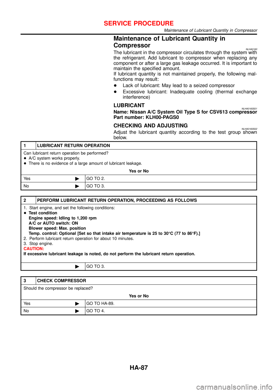
Maintenance of Lubricant Quantity in
Compressor
NLHA0160The lubricant in the compressor circulates through the system with
the refrigerant. Add lubricant to compressor when replacing any
component or after a large gas leakage occurred. It is important to
maintain the specified amount.
If lubricant quantity is not maintained properly, the following mal-
functions may result:
+Lack of lubricant: May lead to a seized compressor
+Excessive lubricant: Inadequate cooling (thermal exchange
interference)
LUBRICANTNLHA0160S01Name: Nissan A/C System Oil Type S for CSV613 compressor
Part number: KLH00-PAGS0
CHECKING AND ADJUSTINGNLHA0160S02Adjust the lubricant quantity according to the test group shown
below.
1 LUBRICANT RETURN OPERATION
Can lubricant return operation be performed?
+A/C system works properly.
+There is no evidence of a large amount of lubricant leakage.
YesorNo
Ye s©GO TO 2.
No©GO TO 3.
2 PERFORM LUBRICANT RETURN OPERATION, PROCEEDING AS FOLLOWS
1. Start engine, and set the following conditions:
+Test condition
Engine speed: Idling to 1,200 rpm
A/C or AUTO switch: ON
Blower speed: Max. position
Temp. control: Optional [Set so that intake air temperature is 25 to 30°C (77 to 86°F).]
2. Perform lubricant return operation for about 10 minutes.
3. Stop engine.
CAUTION:
If excessive lubricant leakage is noted, do not perform the lubricant return operation.
©GO TO 3.
3 CHECK COMPRESSOR
Should the compressor be replaced?
YesorNo
Ye s©GO TO HA-89.
No©GO TO 4.
SERVICE PROCEDURE
Maintenance of Lubricant Quantity in Compressor
HA-87
Page 2679 of 3051
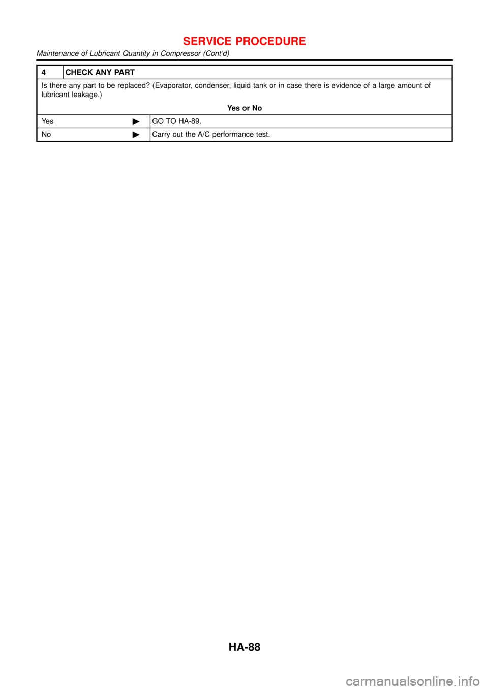
4 CHECK ANY PART
Is there any part to be replaced? (Evaporator, condenser, liquid tank or in case there is evidence of a large amount of
lubricant leakage.)
YesorNo
Ye s©GO TO HA-89.
No©Carry out the A/C performance test.
SERVICE PROCEDURE
Maintenance of Lubricant Quantity in Compressor (Cont’d)
HA-88
Page 2680 of 3051
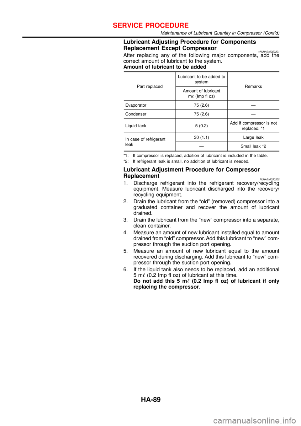
Lubricant Adjusting Procedure for Components
Replacement Except Compressor
=NLHA0160S0201After replacing any of the following major components, add the
correct amount of lubricant to the system.
Amount of lubricant to be added
Part replacedLubricant to be added to
system
Remarks
Amount of lubricant
m!(Imp fl oz)
Evaporator 75 (2.6)—
Condenser 75 (2.6)—
Liquid tank 5 (0.2)Add if compressor is not
replaced. *1
In case of refrigerant
leak30 (1.1) Large leak
—Small leak *2
*1: If compressor is replaced, addition of lubricant is included in the table.
*2: If refrigerant leak is small, no addition of lubricant is needed.
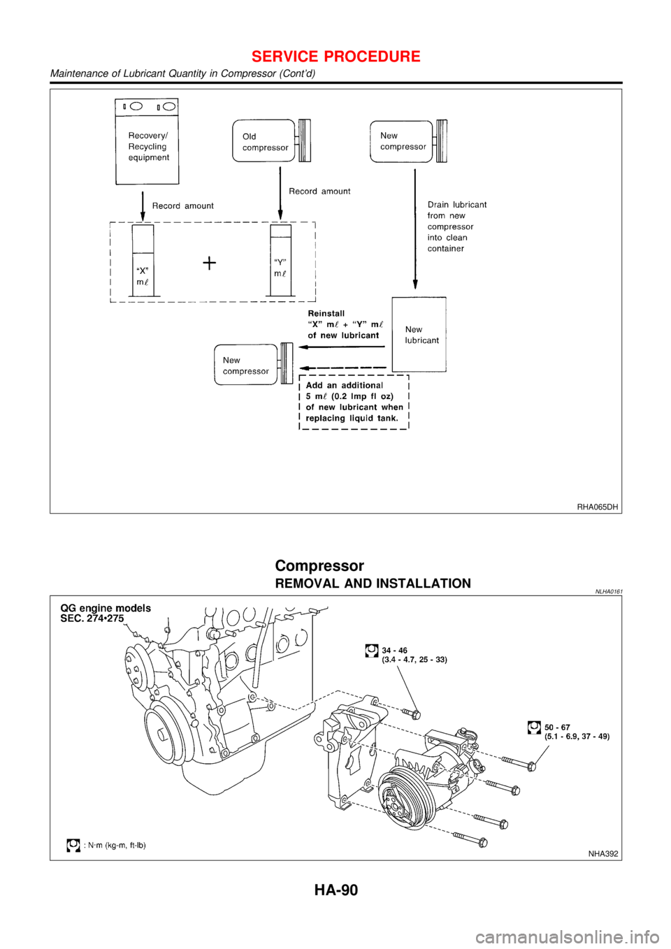
Lubricant Adjustment Procedure for Compressor
Replacement
NLHA0160S02021. Discharge refrigerant into the refrigerant recovery/recycling
equipment. Measure lubricant discharged into the recovery/
recycling equipment.
2. Drain the lubricant from the“old”(removed) compressor into a
graduated container and recover the amount of lubricant
drained.
3. Drain the lubricant from the“new”compressor into a separate,
clean container.
4. Measure an amount of new lubricant installed equal to amount
drained from“old”compressor. Add this lubricant to“new”com-
pressor through the suction port opening.
5. Measure an amount of new lubricant equal to the amount
recovered during discharging. Add this lubricant to“new”com-
pressor through the suction port opening.
6. If the liquid tank also needs to be replaced, add an additional
5m!(0.2 Imp fl oz) of lubricant at this time.
Do not add this 5 m!(0.2 Imp fl oz) of lubricant if only
replacing the compressor.
SERVICE PROCEDURE
Maintenance of Lubricant Quantity in Compressor (Cont’d)
HA-89
Page 2681 of 3051
RHA065DH
Compressor
REMOVAL AND INSTALLATIONNLHA0161
NHA392
SERVICE PROCEDURE
Maintenance of Lubricant Quantity in Compressor (Cont’d)
HA-90
Page 2691 of 3051
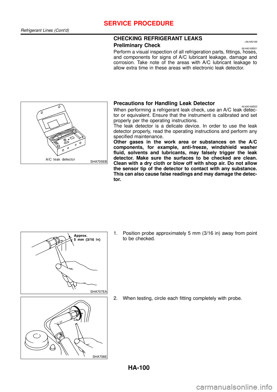
CHECKING REFRIGERANT LEAKS=NLHA0168Preliminary CheckNLHA0168S01Perform a visual inspection of all refrigeration parts, fittings, hoses,
and components for signs of A/C lubricant leakage, damage and
corrosion. Take note of the areas with A/C lubricant leakage to
allow extra time in these areas with electronic leak detector.
SHA705EB
Precautions for Handling Leak DetectorNLHA0168S02When performing a refrigerant leak check, use an A/C leak detec-
tor or equivalent. Ensure that the instrument is calibrated and set
properly per the operating instructions.
The leak detector is a delicate device. In order to use the leak
detector properly, read the operating instructions and perform any
specified maintenance.
Other gases in the work area or substances on the A/C
components, for example, anti-freeze, windshield washer
fluid, solvents and lubricants, may falsely trigger the leak
detector. Make sure the surfaces to be checked are clean.
Clean with a dry cloth or blow off with shop air. Do not allow
the sensor tip of the detector to contact with any substance.
This can also cause false readings and may damage the detec-
tor.
SHA707EA
1. Position probe approximately 5 mm (3/16 in) away from point
to be checked.
SHA706E
2. When testing, circle each fitting completely with probe.
SERVICE PROCEDURE
Refrigerant Lines (Cont’d)
HA-100
Page 2768 of 3051
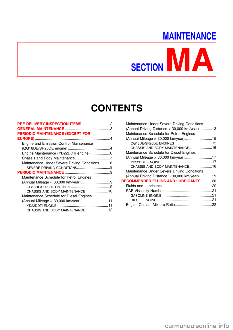
MAINTENANCE
SECTION
MA
CONTENTS
PRE-DELIVERY INSPECTION ITEMS............................2
GENERAL MAINTENANCE............................................3
PERIODIC MAINTENANCE (EXCEPT FOR
EUROPE).........................................................................4
Engine and Emission Control Maintenance
(QG18DE/SR20DE engine) .........................................4
Engine Maintenance (YD22DDTi engine) ...................6
Chassis and Body Maintenance ..................................7
Maintenance Under Severe Driving Conditions ..........8
SEVERE DRIVING CONDITIONS................................8
PERIODIC MAINTENANCE............................................9
Maintenance Schedule for Petrol Engines
(Annual Mileage < 30,000 km/year) ............................9
QG18DE/SR20DE ENGINES......................................9
CHASSIS AND BODY MAINTENANCE......................10
Maintenance Schedule for Diesel Engines
(Annual Mileage < 30,000 km/year) .......................... 11
YD22DDTI ENGINE.................................................. 11
CHASSIS AND BODY MAINTENANCE......................12Maintenance Under Severe Driving Conditions
(Annual Driving Distance < 30,000 km/year) ............13
Maintenance Schedule for Petrol Engines
(Annual Mileage > 30,000 km/year) ..........................15
QG18DE/SR20DE ENGINES....................................15
CHASSIS AND BODY MAINTENANCE......................16
Maintenance Schedule for Diesel Engines
(Annual Mileage > 30,000 km/year) ..........................17
YD22DDTI ENGINE..................................................17
CHASSIS AND BODY MAINTENANCE......................18
Maintenance Under Severe Driving Conditions
(Annual Driving Distance > 30,000 km/year) ............19
RECOMMENDED FLUIDS AND LUBRICANTS...........20
Fluids and Lubricants ................................................20
SAE Viscosity Number ..............................................21
GASOLINE ENGINE.................................................21
DIESEL ENGINE......................................................21
Engine Coolant Mixture Ratio....................................22