2001 NISSAN ALMERA TINO maintenance
[x] Cancel search: maintenancePage 1048 of 3051
Basic Inspection (Models with Throttle Opener)NLEC1369Precaution:
Perform Basic Inspection without electrical or mechanical
loads applied;
+Headlamp switch is OFF,
On vehicle equipped with daytime light systems, set lighting
switch to the 1st position to light only small lamps.
+Air conditioner switch is OFF,
+Rear window defogger switch is OFF,
+Steering wheel is in the straight-ahead position, etc.
1 INSPECTION START
1. Check service records for any recent repairs that may indicate a related problem, or a current need for scheduled
maintenance.
2. Open engine hood and check the following:
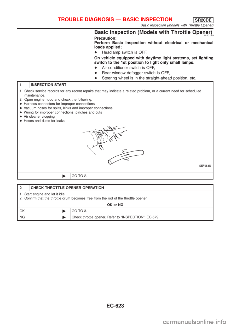
+Harness connectors for improper connections
+Vacuum hoses for splits, kinks and improper connections
+Wiring for improper connections, pinches and cuts
+Air cleaner clogging
+Hoses and ducts for leaks
SEF983U
©GO TO 2.
2 CHECK THROTTLE OPENER OPERATION
1. Start engine and let it idle.
2. Confirm that the throttle drum becomes free from the rod of the throttle opener.
OK or NG
OK©GO TO 3.
NG©Check throttle opener. Refer to ªINSPECTIONº, EC-579.
TROUBLE DIAGNOSIS Ð BASIC INSPECTIONSR20DE
Basic Inspection (Models with Throttle Opener)
EC-623
Page 1063 of 3051
Basic Inspection (Models without Throttle
Opener)
=NLEC1930Precaution:
Perform Basic Inspection without electrical or mechanical
loads applied;
+Headlamp switch is OFF,
+On vehicles equipped with daytime running light system, set
lighting switch to the 1st position to light only small lamps.
+Air conditioner switch is OFF,
+Rear window defogger switch is OFF,
+Steering wheel is in the straight-ahead position, etc.
1 INSPECTION START
1. Check service records for any recent repairs that may indicate a related problem, or the current need for scheduled
maintenance.
2. Open engine hood and check the following:
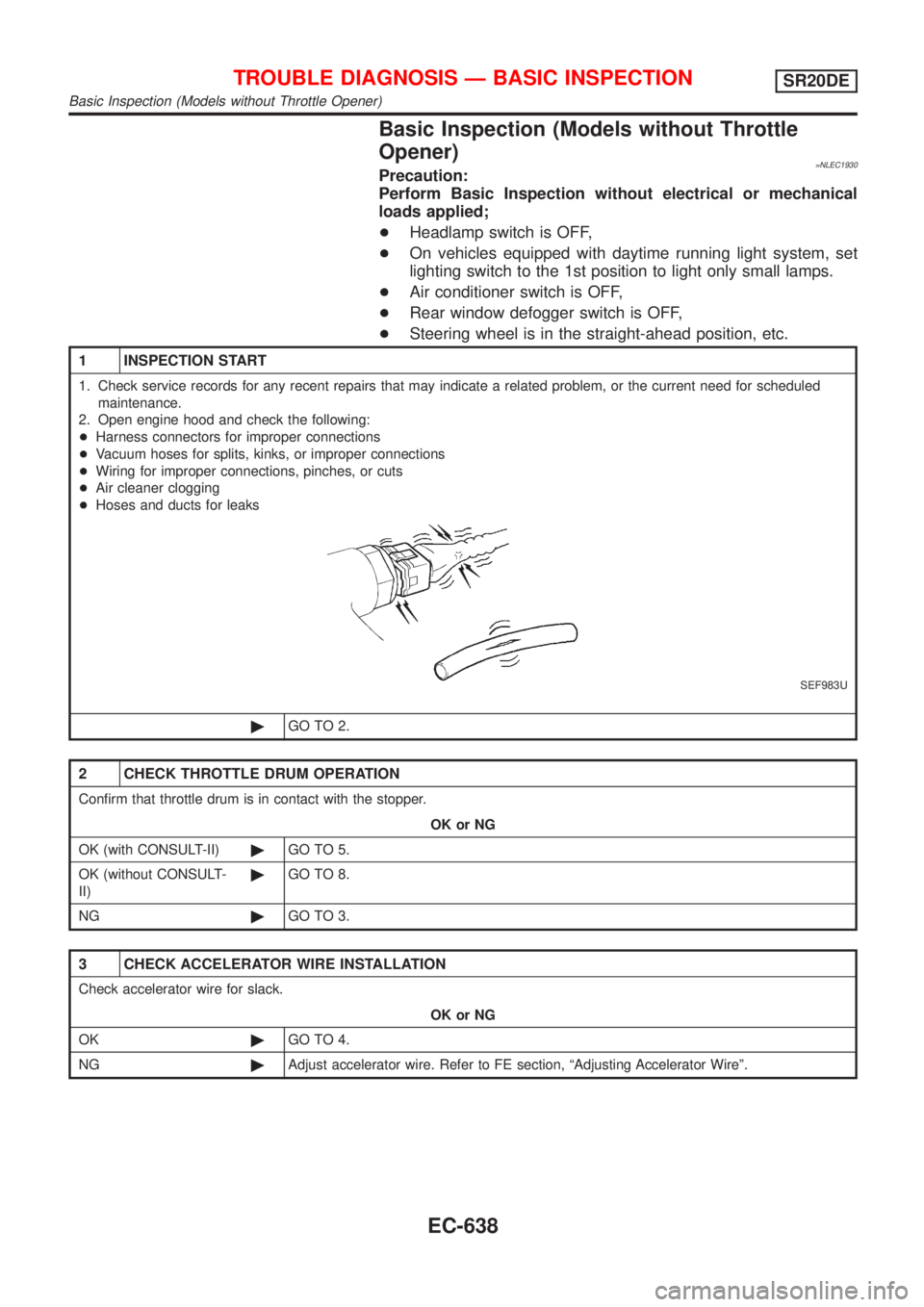
+Harness connectors for improper connections
+Vacuum hoses for splits, kinks, or improper connections
+Wiring for improper connections, pinches, or cuts
+Air cleaner clogging
+Hoses and ducts for leaks
SEF983U
©GO TO 2.
2 CHECK THROTTLE DRUM OPERATION
Confirm that throttle drum is in contact with the stopper.
OK or NG
OK (with CONSULT-II)©GO TO 5.
OK (without CONSULT-
II)©GO TO 8.
NG©GO TO 3.
3 CHECK ACCELERATOR WIRE INSTALLATION
Check accelerator wire for slack.
OK or NG
OK©GO TO 4.
NG©Adjust accelerator wire. Refer to FE section, ªAdjusting Accelerator Wireº.
TROUBLE DIAGNOSIS Ð BASIC INSPECTIONSR20DE
Basic Inspection (Models without Throttle Opener)
EC-638
Page 1222 of 3051
4 CHECK FUEL PRESSURE
1. Release fuel pressure to zero.
Refer to EC-577.
2. Install fuel pressure gauge and check fuel pressure.
At idling:
When fuel pressure regulator valve vacuum hose is connected.
235 kPa (2.35 bar, 2.4 kg/cm
2, 34 psi)
When fuel pressure regulator valve vacuum hose is disconnected.
294 kPa (2.94 bar, 3.0 kg/cm
2, 43 psi)
OK or NG
OK©GO TO 6.
NG©GO TO 5.
5 DETECT MALFUNCTIONING PART
Check the following.
+Fuel pump and circuit (Refer to EC-1032.)
+Fuel pressure regulator (Refer to EC-578.)
+Fuel lines (Refer to ªENGINE MAINTENANCEº in MA section.)
+Fuel filter for clogging
©Repair or replace.
6 CHECK MASS AIR FLOW SENSOR
With CONSULT-II
Check ªMASS AIR FLOWº in ªDATA MONITORº mode with CONSULT-II.
at idling: 2.5 - 5.0 g´m/sec
at 2,500 rpm: 7.1 - 12.5 g´m/sec
With GST
Check mass air flow sensor signal in MODE 1 with GST.
at idling: 2.5 - 5.0 g´m/sec
at 2,500 rpm: 7.1 - 12.5 g´m/sec
OK or NG
OK©GO TO 7.
NG©Check connectors for rusted terminals or loose connections in the mass air flow sensor
circuit or engine grounds. Refer to EC-679.
DTC P0171 FUEL INJECTION SYSTEM FUNCTION
(LEAN SIDE)
SR20DE
Diagnostic Procedure (Cont'd)
EC-797
Page 1491 of 3051
Precautions for Supplemental Restraint System
(SRS) ªAIR BAGº and ªSEAT BELT
PRE-TENSIONERº
NLEC1263The Supplemental Restraint System ªAIR BAGº and ªSEAT BELT PRE-TENSIONERº, used along with a seat
belt, help to reduce the risk or severity of injury to the driver and front passenger in a frontal collision. The
Supplemental Restraint System consists of air bag modules (located in the center of the steering wheel and
on the instrument panel on the passenger side), seat belt pre-tensioners, a diagnosis sensor unit, warning
lamp, wiring harness and spiral cable.
In addition to the supplemental air bag modules for a frontal collision, the supplemental side air bag used along
with the seat belt helps to reduce the risk or severity of injury to the driver and front passenger in a side col-
lision. The supplemental side air bag consists of air bag modules (located in the outer side of front seats),
satellite sensor, diagnosis sensor unit (one of components of supplemental air bags for a frontal collision),
wiring harness, warning lamp (one of components of supplemental air bags for a frontal collision). Information
necessary to service the system safely is included in theRS sectionof this Service Manual.
WARNING:
+To avoid rendering the SRS inoperative, which could increase the risk of personal injury or death
in the event of a collision which would result in air bag inflation, all maintenance must be performed
by an authorized NISSAN dealer.
+Improper maintenance, including incorrect removal and installation of the SRS, can lead to per-
sonal injury caused by unintentional activation of the system.
+Do not use electrical test equipment on any circuit related to the SRS unless instructed to in this
Service Manual. SRS wiring harnesses can be identified with yellow harness connector (and with
yellow harness protector or yellow insulation tape before the harness connectors).
SEF706Y
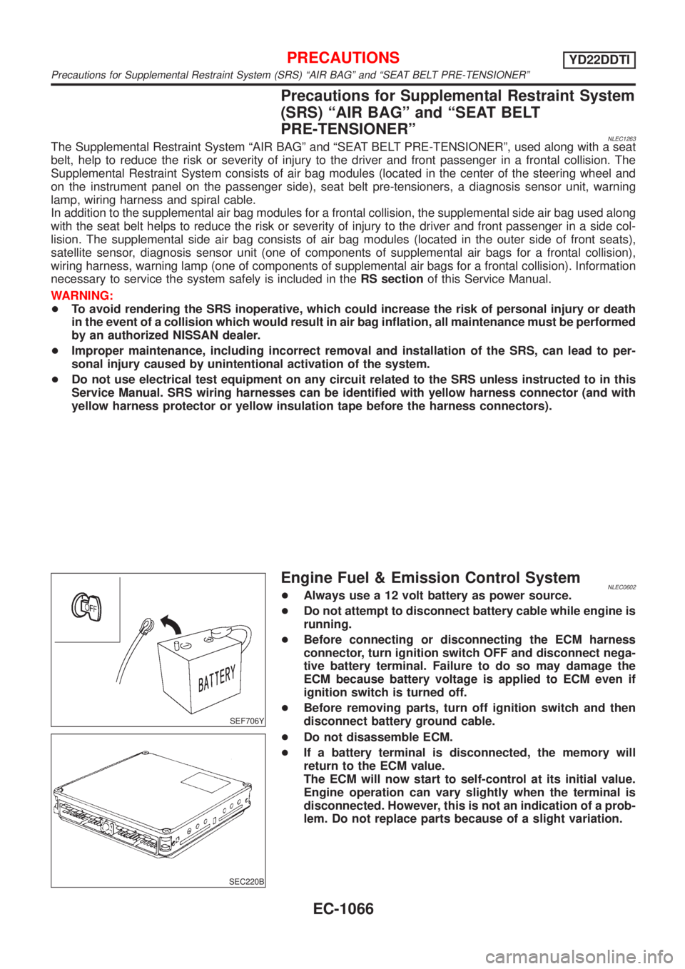
Engine Fuel & Emission Control SystemNLEC0602+Always use a 12 volt battery as power source.
+Do not attempt to disconnect battery cable while engine is
running.
+Before connecting or disconnecting the ECM harness
connector, turn ignition switch OFF and disconnect nega-
tive battery terminal. Failure to do so may damage the
ECM because battery voltage is applied to ECM even if
ignition switch is turned off.
+Before removing parts, turn off ignition switch and then
disconnect battery ground cable.
SEC220B
+Do not disassemble ECM.
+If a battery terminal is disconnected, the memory will
return to the ECM value.
The ECM will now start to self-control at its initial value.
Engine operation can vary slightly when the terminal is
disconnected. However, this is not an indication of a prob-
lem. Do not replace parts because of a slight variation.
PRECAUTIONSYD22DDTI
Precautions for Supplemental Restraint System (SRS) ªAIR BAGº and ªSEAT BELT PRE-TENSIONERº
EC-1066
Page 1735 of 3051
Supplemental Restraint System (SRS) ªAIR
BAGº and ªSEAT BELT PRE-TENSIONERº
NLEL0001The Supplemental Restraint System such as ªAIR BAGº and ªSEAT BELT PRE-TENSIONERº used along with
a seat belt, helps to reduce the risk or severity of injury to the driver and front passenger for certain types of
collision. The SRS system composition which is available to NISSAN MODEL V10 is as follows (The compo-
sition varies according to the destination and optional equipment.):
+For a frontal collision
The Supplemental Restraint System consists of driver air bag module (located in the center of the steer-
ing wheel), front passenger air bag module (located on the instrument panel on passenger side), front seat
belt pre-tensioners, a diagnosis sensor unit, warning lamp, wiring harness and spiral cable.
+For a side collision
The Supplemental Restraint System consists of front side air bag module (located in the outer side of front
seat), side air bag (satellite) sensor, diagnosis sensor unit (one of components of air bags for a frontal
collision), wiring harness, warning lamp (one of components of air bags for a frontal collision).
Information necessary to service the system safely is included in theRS sectionof this Service Manual.
WARNING:
+To avoid rendering the SRS inoperative, which could increase the risk of personal injury or death
in the event of a collision which would result in air bag inflation, all maintenance should be per-
formed by an authorized NISSAN dealer.
+Improper maintenance, including incorrect removal and installation of the SRS, can lead to per-
sonal injury caused by unintentional activation of the system. For removal of Spiral Cable and Air
Bag Module, see the RS section.
+Do not use electrical test equipment on any circuit related to the SRS unless instructed to in this
Service Manual. Spiral cable and wiring harnesses covered with yellow insulation tape either just
before the harness connectors or for the complete harness are related to the SRS.
Wiring Diagrams and Trouble DiagnosisNLEL0002When you read wiring diagrams, refer to the following:
+Refer to GI-11, ªHOW TO READ WIRING DIAGRAMSº
+Refer to EL-10, ªPOWER SUPPLY ROUTINGº for power distribution circuit
When you perform trouble diagnosis, refer to the following:
+Refer to GI-32, ªHOW TO FOLLOW TEST GROUP IN TROUBLE DIAGNOSISº
+Refer to GI-21, ªHOW TO PERFORM EFFICIENT DIAGNOSIS FOR AN ELECTRICAL INCIDENTº
Check for any Service bulletins before servicing the vehicle.
PRECAUTIONS
Supplemental Restraint System (SRS) ªAIR BAGº and ªSEAT BELT PRE-TENSIONERº
EL-4
Page 2542 of 3051

PrecautionsNLGI0001Observe the following precautions to ensure safe and proper
servicing. These precautions are not described in each indi-
vidual section.
SGI646
PRECAUTIONS FOR SUPPLEMENTAL RESTRAINT
SYSTEM (SRS)“AIR BAG”AND“SEAT BELT
PRE-TENSIONER”
NLGI0001S01The Supplemental Restraint System such as“AIR BAG”and“SEAT
BELT PRE-TENSIONER”used along with a seat belt, helps to
reduce the risk or severity of injury to the driver and front passen-
ger for certain types of collision. The SRS system composition
which is available to NISSAN MODEL V10 is as follows (The com-
position varies according to the destination and optional equip-
ment.):
+For a frontal collision
The Supplemental Restraint System consists of driver air bag
module (located in the center of the steering wheel), front pas-
senger air bag module (located on the instrument panel on
passenger side), front seat belt pre-tensioners, a diagnoses
sensor unit, warning lamp, wiring harness and spiral cable.
+For a side collision
The Supplemental Restraint System consists of front side air
bag module (located in the outer side of front seat), side air bag
(satellite) sensor, diagnoses sensor unit (one of components of
air bags for a frontal collision), wiring harness, warning lamp
(one of components of air bags for a frontal collision).
Information necessary to service the system safely is included in
theRS sectionof this Service Manual.
WARNING:
+To avoid rendering the SRS inoperative, which could
increase the risk of personal injury or death in the event
of a collision which would result in air bag inflation, all
maintenance should be performed by an authorized
NISSAN dealer.
+Improper maintenance, including incorrect removal and
installation of the SRS, can lead to personal injury caused
by unintentional activation of the system. For removal of
Spiral Cable and Air Bag Module, see the RS section.
+Do not use electrical test equipment on any circuit related
to the SRS unless instructed to in this Service Manual.
Spiral cable and wiring harnesses covered with yellow
insulation tape either just before the harness connectors
or for the complete harness are related to the SRS.
PRECAUTIONS FOR NATS (NISSAN ANTI-THEFT
SYSTEM)
NLGI0001S02NATS will immobilize the engine if someone tries to start it without
the registered key of NATS.
Both of the originally supplied ignition key IDs have been NATS
registered.
PRECAUTIONS
Precautions
GI-3
Page 2592 of 3051
HEATER &
AIR CONDITIONER
SECTION
HA
CONTENTS
PRECAUTIONS...............................................................2
Supplemental Restraint System (SRS)″AIR
BAG″and″SEAT BELT PRE-TENSIONER″...............2
Precautions for Working with HFC-134a (R-134a) .....2
General Refrigerant Precautions .................................2
Precautions for Refrigerant Connection ......................3
Precautions for Servicing Compressor ........................5
Precautions for Service Equipment .............................6
Wiring Diagrams and Trouble Diagnosis .....................8
PREPARATION...............................................................9
Special Service Tools ..................................................9
HFC-134a (R-134a) Service Tools and
Equipment ..................................................................10
DESCRIPTION...............................................................12
Refrigeration System .................................................12
CSV613 Variable Displacement Compressor............13
Component Layout ....................................................17
Control Operation ......................................................18
Discharge Air Flow.....................................................19
System Description ....................................................20
TROUBLE DIAGNOSES................................................21
Component Location..................................................21
Wiring Diagram - Heater............................................23
Circuit Diagram - Air Conditioner...............................26
Wiring Diagram - A/C, M - .........................................27
How to Perform Trouble Diagnoses for Quick
and Accurate Repair ..................................................40
Operational Check .....................................................41Intake Door ................................................................43
Mode Door .................................................................47
Air Mix Door ...............................................................49
Max Hot Door (For Scandinavia and Cold Spec
Models) ......................................................................51
Blower Motor..............................................................55
Magnet Clutch............................................................62
Insufficient Cooling ....................................................75
Insufficient Heating ....................................................83
Noise ..........................................................................84
SERVICE PROCEDURE................................................85
HFC-134a (R-134a) Service Procedure ....................85
Maintenance of Lubricant Quantity in
Compressor ...............................................................87
Compressor ...............................................................90
Compressor Clutch - CSV613 (CALSONIC
make) .........................................................................92
Heater & Cooling Unit (Heater Core) ........................95
A/C Evaporator ..........................................................96
Blower Unit ................................................................97
Refrigerant Lines .......................................................98
Belt ...........................................................................102
Idle Air Control Valve (IACV) - Auxiliary Air
Control (AAC) Valve ................................................103
Ventilation Air Filter ..................................................103
SERVICE DATA AND SPECIFICATIONS (SDS).......104
Manual .....................................................................104
Page 2593 of 3051

Supplemental Restraint System (SRS) “AIR
BAG” and “SEAT BELT PRE-TENSIONER”
NLHA0190The Supplemental Restraint System such as “AIR BAG” and “SEAT BELT PRE-TENSIONER” used along with
a seat belt, helps to reduce the risk or severity of injury to the driver and front passenger for certain types of
collision. The SRS system composition which is available to NISSAN MODEL V10 is as follows (The compo-
sition varies according to the destination and optional equipment.):
+For a frontal collision
The Supplemental Restraint System consists of driver air bag module (located in the center of the steer-
ing wheel), front passenger air bag module (located on the instrument panel on passenger side), front seat
belt pre-tensioners, a diagnosis sensor unit, warning lamp, wiring harness and spiral cable.
+For a side collision
The Supplemental Restraint System consists of front side air bag module (located in the outer side of front
seat), side air bag (satellite) sensor, diagnosis sensor unit (one of components of air bags for a frontal
collision), wiring harness, warning lamp (one of components of air bags for a frontal collision).
Information necessary to service the system safely is included in theRS sectionof this Service Manual.
WARNING:
+To avoid rendering the SRS inoperative, which could increase the risk of personal injury or death
in the event of a collision which would result in air bag inflation, all maintenance should be per-
formed by an authorized NISSAN dealer.
+Improper maintenance, including incorrect removal and installation of the SRS, can lead to per-
sonal injury caused by unintentional activation of the system. For removal of Spiral Cable and Air
Bag Module, see the RS section.
+Do not use electrical test equipment on any circuit related to the SRS unless instructed to in this
Service Manual. Spiral cable and wiring harnesses covered with yellow insulation tape either just
before the harness connectors or for the complete harness are related to the SRS.
Precautions for Working with HFC-134a
(R-134a)
NLHA0113WARNING:
+CFC-12 (R-12) refrigerant and HFC-134a (R-134a) refrigerant are not compatible. These refrigerants
must never be mixed, even in the smallest amounts. If the refrigerants are mixed, compressor fail-
ure is likely to occur.
+Use only specified lubricant for the HFC-134a (R-134a) A/C system and HFC-134a (R-134a) compo-
nents. If lubricant other than that specified is used, compressor failure is likely to occur.
+The specified HFC-134a (R-134a) lubricant rapidly absorbs moisture from the atmosphere. The fol-
lowing handling precautions must be observed:
a) When removing refrigerant components from a vehicle, immediately cap (seal) the component to
minimize the entry of moisture from the atmosphere.
b) When installing refrigerant components to a vehicle, do not remove the caps (unseal) until just
before connecting the components. Connect all refrigerant loop components as quickly as pos-
sible to minimize the entry of moisture into system.
c) Only use the specified lubricant from a sealed container. Immediately reseal containers of lubri-
cant. Without proper sealing, lubricant will become moisture saturated and should not be used.
d) Avoid breathing A/C refrigerant and lubricant vapor or mist. Exposure may irritate eyes, nose
and throat. Remove R-134a from the A/C system, using certified service equipment meeting
requirements of R-134a recycling equipment, or R-134a recovery equipment. If accidental system
discharge occurs, ventilate work area before resuming service. Additional health and safety
information may be obtained from refrigerant and lubricant manufacturers.
e) Do not allow lubricant (Nissan A/C System Oil Type S) to come in contact with styrofoam parts.
Damage may result.
General Refrigerant PrecautionsNLHA0114WARNING:
+Do not release refrigerant into the air. Use approved recovery/recycling equipment to capture the
refrigerant every time an air conditioning system is discharged.
+Always wear eye and hand protection (goggles and gloves) when working with any refrigerant or
air conditioning system.
PRECAUTIONS
Supplemental Restraint System (SRS) “AIR BAG” and “SEAT BELT PRE-TENSIONER”
HA-2