Page 1315 of 3051
7 CHECK RADIATOR CAP
Apply pressure to cap with a tester.
SLC755A
Radiator cap relief pressure:
59 - 98 kPa (0.59 - 0.98 bar, 0.6 - 1.0 kg/cm2,9-14psi)
OK or NG
OK©GO TO 8.
NG©Replace radiator cap.
8 CHECK THERMOSTAT
1. Check valve seating condition at normal room temperatures.
It should seat tightly.
2. Check valve opening temperature and valve lift.
SLC343
Valve opening temperature:
82ÉC (180ÉF) [standard]
Valve lift:
More than 9 mm/95ÉC (0.35 in/203ÉF)
3. Check if valve is closed at 5ÉC (9ÉF) below valve opening temperature.
For details, refer to LC-15, ªThermostatº.
OK or NG
OK©GO TO 9.
NG©Replace thermostat
9 CHECK ENGINE COOLANT TEMPERATURE SENSOR
Refer to ªCOMPONENT INSPECTIONº, EC-699.
OK or NG
OK©GO TO 10.
NG©Replace engine coolant temperature sensor.
DTC P1217 OVERHEAT (COOLING SYSTEM)SR20DE
Diagnostic Procedure (Cont'd)
EC-890
Page 1323 of 3051

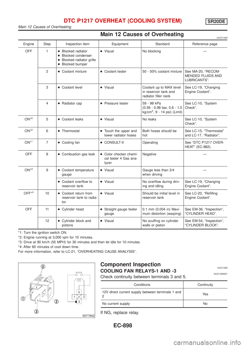
Main 12 Causes of Overheating=NLEC1625
Engine Step Inspection item Equipment Standard Reference page
OFF 1+Blocked radiator
+Blocked condenser
+Blocked radiator grille
+Blocked bumper+Visual No blocking Ð
2+Coolant mixture+Coolant tester 50 - 50% coolant mixture See MA-20, ªRECOM-
MENDED FLUIDS AND
LUBRICANTSº.
3+Coolant level+Visual Coolant up to MAX level
in reservoir tank and
radiator filler neckSee LC-19, ªChanging
Engine Coolantº.
4+Radiator cap+Pressure tester 59 - 98 kPa
(0.59 - 0.98 bar, 0.6 - 1.0
kg/cm
2,9-14psi) (Limit)See LC-10, ªSystem
Checkº.
ON*
25+Coolant leaks+Visual No leaks See LC-10, ªSystem
Checkº.
ON*
26+Thermostat+Touch the upper and
lower radiator hosesBoth hoses should be
hotSee LC-15, ªThermostatº
and LC-17, ªRadiatorº.
ON*
17+Cooling fan+CONSULT-II Operating See ªDTC P1217 OVER-
HEATº (EC-882).
OFF 8+Combustion gas leak+Color checker chemi-
cal tester 4 Gas ana-
lyzerNegative Ð
ON*
39+Coolant temperature
gauge+Visual Gauge less than 3/4
when drivingÐ
+Coolant overflow to
reservoir tank+Visual No overflow during driv-
ing and idlingSee LC-19, ªChanging
Engine Coolantº.
OFF*
410+Coolant return from
reservoir tank to radia-
tor+Visual Should be initial level in
reservoir tankSee LC-20, ªRefilling
Engine Coolantº.
OFF 11+Cylinder head+Straight gauge feeler
gauge0.1 mm (0.004 in) Maxi-
mum distortion (warping)See EM-36, ªInspectionº,
ªCYLINDER HEADº.
12+Cylinder block and
pistons+Visual No scuffing on cylinder
walls or pistonSee EM-54, ªInspectionº,
ªCYLINDER BLOCKº.
*1: Turn the ignition switch ON.
*2: Engine running at 3,000 rpm for 10 minutes.
*3: Drive at 90 km/h (55 MPH) for 30 minutes and then let idle for 10 minutes.
*4: After 60 minutes of cool down time.
For more information, refer to LC-21, ªOVERHEATING CAUSE ANALYSISº.
SEF786Z
Component InspectionNLEC1626COOLING FAN RELAYS-1 AND -3NLEC1626S01Check continuity between terminals 3 and 5.
Conditions Continuity
12V direct current supply between terminals 1 and
2Ye s
No current supply No
If NG, replace relay.
DTC P1217 OVERHEAT (COOLING SYSTEM)SR20DE
Main 12 Causes of Overheating
EC-898
Page 1542 of 3051

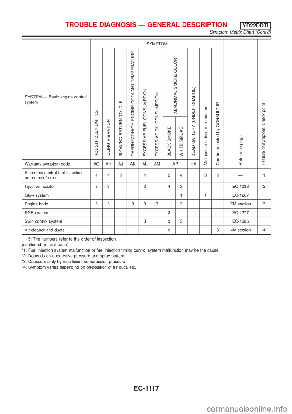
SYSTEM Ð Basic engine control
systemSYMPTOM
Reference page
Feature of symptom, Check pointROUGH IDLE/HUNTING
IDLING VIBRATION
SLOW/NO RETURN TO IDLE
OVERHEAT/HIGH ENGINE COOLANT TEMPERATURE
EXCESSIVE FUEL CONSUMPTION
EXCESSIVE OIL CONSUMPTION
ABNORMAL SMOKE COLOR
DEAD BATTERY (UNDER CHARGE)
Malfunction indicator illuminates.
Can be detected by CONSULT-II?BLACK SMOKE
WHITE SMOKEWarranty symptom code AG AH AJ AK AL AM AP HA
Electronic control fuel injection
pump mainframe44345433Ð*1
Injection nozzle 3 3 3 4 3 EC-1083 *2
Glow system 1 1 EC-1267
Engine body 3 3 3 3 3 3 EM section *3
EGR system 3 EC-1277
Swirl control system 3 3 3 EC-1285
Air cleaner and ducts 3 3 MA section *4
1 - 5: The numbers refer to the order of inspection.
(continued on next page)
*1: Fuel injection system malfunction or fuel injection timing control system malfunction may be the cause.
*2: Depends on open-valve pressure and spray pattern.
*3: Caused mainly by insufficient compression pressure.
*4: Symptom varies depending on off-position of air duct, etc.
TROUBLE DIAGNOSIS Ð GENERAL DESCRIPTIONYD22DDTI
Symptom Matrix Chart (Cont'd)
EC-1117
Page 1544 of 3051
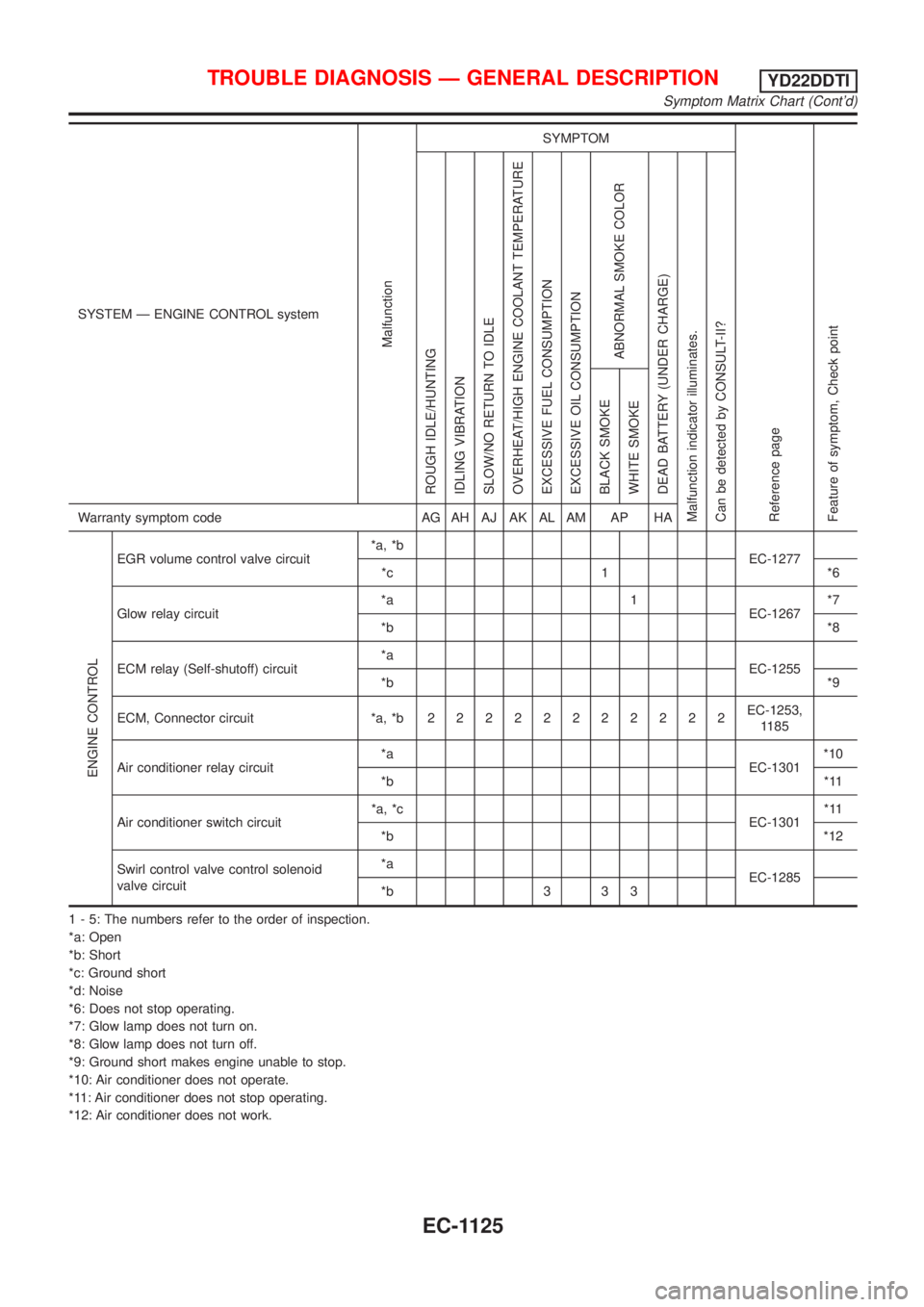
SYSTEM Ð ENGINE CONTROL system
Malfunction
SYMPTOM
Reference page
Feature of symptom, Check pointROUGH IDLE/HUNTING
IDLING VIBRATION
SLOW/NO RETURN TO IDLE
OVERHEAT/HIGH ENGINE COOLANT TEMPERATURE
EXCESSIVE FUEL CONSUMPTION
EXCESSIVE OIL CONSUMPTION
ABNORMAL SMOKE COLOR
DEAD BATTERY (UNDER CHARGE)
Malfunction indicator illuminates.
Can be detected by CONSULT-II?BLACK SMOKE
WHITE SMOKEWarranty symptom code AG AH AJ AK AL AM AP HA
ENGINE CONTROL
Electronic control fuel injection pump
circuit*a, *b 1 1 1
11 Ð
*c, *d 1
Mass air flow sensor circuit*a, *c
1 EC-1143
*b 1
Engine coolant temperature sensor cir-
cuit*a, *b 1 1 1 1 1 EC-1150 *1
Vehicle speed sensor circuit *a, *b 1 EC-1172
1 - 5: The numbers refer to the order of inspection.
(continued on next page)
*a: Open
*b: Short
*c: Ground short
*d: Noise
*1: Compensation according to engine coolant temperature does not function.
TROUBLE DIAGNOSIS Ð GENERAL DESCRIPTIONYD22DDTI
Symptom Matrix Chart (Cont'd)
EC-1119
Page 1546 of 3051
SYSTEM Ð ENGINE CONTROL system
Malfunction
SYMPTOM
Reference page
Feature of symptom, Check pointROUGH IDLE/HUNTING
IDLING VIBRATION
SLOW/NO RETURN TO IDLE
OVERHEAT/HIGH ENGINE COOLANT TEMPERATURE
EXCESSIVE FUEL CONSUMPTION
EXCESSIVE OIL CONSUMPTION
ABNORMAL SMOKE COLOR
DEAD BATTERY (UNDER CHARGE)
Malfunction indicator illuminates.
Can be detected by CONSULT-II?BLACK SMOKE
WHITE SMOKEWarranty symptom code AG AH AJ AK AL AM AP HA
ENGINE CONTROL
Fuel cut system line*a, *c 1 1
EC-1194
*b*2
Accelerator position sensor circuit *a, *b 1 1 EC-1155
Crankshaft position sensor (TDC) circuit*a, *b
1 1 1 1 EC-1166
*d
1 - 5: The numbers refer to the order of inspection.
(continued on next page)
*a: Open
*b: Short
*c: Ground short
*d: Noise
*2: Engine runs on after turning ignition switch OFF.
TROUBLE DIAGNOSIS Ð GENERAL DESCRIPTIONYD22DDTI
Symptom Matrix Chart (Cont'd)
EC-1121
Page 1548 of 3051
SYSTEM Ð ENGINE CONTROL system
Malfunction
SYMPTOM
Reference page
Feature of symptom, Check pointROUGH IDLE/HUNTING
IDLING VIBRATION
SLOW/NO RETURN TO IDLE
OVERHEAT/HIGH ENGINE COOLANT TEMPERATURE
EXCESSIVE FUEL CONSUMPTION
EXCESSIVE OIL CONSUMPTION
ABNORMAL SMOKE COLOR
DEAD BATTERY (UNDER CHARGE)
Malfunction indicator illuminates.
Can be detected by CONSULT-II?BLACK SMOKE
WHITE SMOKEWarranty symptom code AG AH AJ AK AL AM AP HA
ENGINE CONTROL
Start signal circuit *a, *b EC-1293 *3
Accelerator position switch (Idle) circuit*a, *c
EC-1155
*b 1 1 *4
Ignition switch circuit*a
EC-1136
*b*5
Power supply for ECM circuit*a
1 1 EC-1136
*b
1 - 5: The numbers refer to the order of inspection.
(continued on next page)
*a: Open
*b: Short
*c: Ground short
*d: Noise
*3: Start control does not function.
*4: Accelerator position sensor NG signal is output.
*5: Engine does not stop.
TROUBLE DIAGNOSIS Ð GENERAL DESCRIPTIONYD22DDTI
Symptom Matrix Chart (Cont'd)
EC-1123
Page 1550 of 3051

SYSTEM Ð ENGINE CONTROL system
Malfunction
SYMPTOM
Reference page
Feature of symptom, Check pointROUGH IDLE/HUNTING
IDLING VIBRATION
SLOW/NO RETURN TO IDLE
OVERHEAT/HIGH ENGINE COOLANT TEMPERATURE
EXCESSIVE FUEL CONSUMPTION
EXCESSIVE OIL CONSUMPTION
ABNORMAL SMOKE COLOR
DEAD BATTERY (UNDER CHARGE)
Malfunction indicator illuminates.
Can be detected by CONSULT-II?BLACK SMOKE
WHITE SMOKEWarranty symptom code AG AH AJ AK AL AM AP HA
ENGINE CONTROL
EGR volume control valve circuit*a, *b
EC-1277
*c 1 *6
Glow relay circuit*a 1
EC-1267*7
*b*8
ECM relay (Self-shutoff) circuit*a
EC-1255
*b*9
ECM, Connector circuit *a, *b22222222222EC-1253,
1185
Air conditioner relay circuit*a
EC-1301*10
*b*11
Air conditioner switch circuit*a, *c
EC-1301*11
*b*12
Swirl control valve control solenoid
valve circuit*a
EC-1285
*b 3 3 3
1 - 5: The numbers refer to the order of inspection.
*a: Open
*b: Short
*c: Ground short
*d: Noise
*6: Does not stop operating.
*7: Glow lamp does not turn on.
*8: Glow lamp does not turn off.
*9: Ground short makes engine unable to stop.
*10: Air conditioner does not operate.
*11: Air conditioner does not stop operating.
*12: Air conditioner does not work.
TROUBLE DIAGNOSIS Ð GENERAL DESCRIPTIONYD22DDTI
Symptom Matrix Chart (Cont'd)
EC-1125
Page 1627 of 3051
![NISSAN ALMERA TINO 2001 Service Repair Manual TERMI-
NAL
NO.WIRE
COLORITEM CONDITION DATA(DC Voltage)
221 LG/B Cooling fan relay (High)[Engine is running]
+Cooling fans are not operating
+Cooling fans are operating at low speedBATTERY VOLTAGE
(11 NISSAN ALMERA TINO 2001 Service Repair Manual TERMI-
NAL
NO.WIRE
COLORITEM CONDITION DATA(DC Voltage)
221 LG/B Cooling fan relay (High)[Engine is running]
+Cooling fans are not operating
+Cooling fans are operating at low speedBATTERY VOLTAGE
(11](/manual-img/5/57352/w960_57352-1626.png)
TERMI-
NAL
NO.WIRE
COLORITEM CONDITION DATA(DC Voltage)
221 LG/B Cooling fan relay (High)[Engine is running]
+Cooling fans are not operating
+Cooling fans are operating at low speedBATTERY VOLTAGE
(11 - 14V)
[Engine is running]
+Cooling fans are operating at high speedApproximately 0.1V
On Board Diagnosis LogicNLEC0663This diagnosis continuously monitors the engine coolant temperature.
If the cooling fan or another component in the cooling system malfunctions, engine coolant temperature will
rise.
When the engine coolant temperature reaches an abnormally high temperature condition, a malfunction is
indicated.
DTC Malfunction is detected when ... Check Items (Possible Cause)
P1217
0208+Cooling fan does not operate properly (Overheat).
+Cooling fan system does not operate properly
(Overheat).
+Engine coolant was not added to the system using
the proper filling method.+Harness or connectors
(The cooling fan circuit is open or shorted.)
+Cooling fan
+Radiator hose
+Radiator
+Radiator cap
+Water pump
+Thermostat
+Engine coolant temperature sensor
For more information, refer to ªMAIN 12 CAUSES OF
OVERHEATINGº, EC-1217.
CAUTION:
When a malfunction is indicated, be sure to replace the coolant following the procedure in the LC-59,
ªChanging Engine Coolantº. Also, replace the engine oil.
1) Fill radiator with coolant up to specified level with a filling speed of 2 liters per minute. Be sure
to use coolant with the proper mixture ratio. Refer to MA-22, ªEngine Coolant Mixture Ratioº.
2) After refilling coolant, run engine to ensure that no water-flow noise is emitted.
DTC P1217 OVER HEATYD22DDTI
ECM Terminals and Reference Value (Cont'd)
EC-1202