Page 2284 of 3051
SEM886F
InstallationNLEM01071. Install crankshaft sprocket on crankshaft.
+Make sure mating marks on crankshaft sprocket face front
of engine.
SEM890F
2. Position crankshaft so that No. 1 piston is at TDC and key way
is at 12 o'clock.
SEM891F
3. Install slack side timing chain guide and timing chain tension
guide.
SEM892F
4. Install timing chain on crankshaft sprocket.
+Support chain with a suitable tool to keep the mating mark
aligned.
+Set timing chain by aligning its mating mark with that on
the crankshaft sprocket.
+Make sure sprocket's mating mark faces engine front.
SEM905F
5. Install camshaft sprocket.
+Set timing chain by aligning mating marks with those of
camshaft sprockets.
TIMING CHAINQG
Installation
EM-27
Page 2303 of 3051
SEM900F
SEM614EC
SEM901F
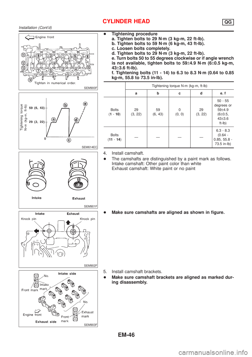
+Tightening procedure
a. Tighten bolts to 29 N´m (3 kg-m, 22 ft-lb).
b. Tighten bolts to 59 N´m (6 kg-m, 43 ft-lb).
c. Loosen bolts completely.
d. Tighten bolts to 29 N´m (3 kg-m, 22 ft-lb).
e. Turn bolts 50 to 55 degrees clockwise or if angle wrench
is not available, tighten bolts to 59±4.9 N´m (6±0.5 kg-m,
43±3.6 ft-lb).
f. Tightening bolts (11 - 14) to 6.3 to 8.3 N´m (0.64 to 0.85
kg-m, 55.8 to 73.5 in-lb).
Tightening torque N´m (kg-m, ft-lb)
abcde,f
Bolts
(1-10)29
(3, 22)59
(6, 43)0
(0, 0)29
(3, 22)50-55
degrees or
59±4.9
(6±0.5,
43±3.6
ft-lb)
Bolts
(11-14)ÐÐÐÐ6.3 - 8.3
(0.64 -
0.85, 55.8 -
73.5 in-lb)
4. Install camshaft.
+The camshafts are distinguished by a paint mark as follows.
Intake camshaft: Other paint color than white
Exhaust camshaft: White paint or no paint
SEM902F
+Make sure camshafts are aligned as shown in figure.
SEM903F
5. Install camshaft brackets.
+Make sure camshaft brackets are aligned as marked dur-
ing disassembly.
CYLINDER HEADQG
Installation (Cont'd)
EM-46
Page 2319 of 3051
SEM116F
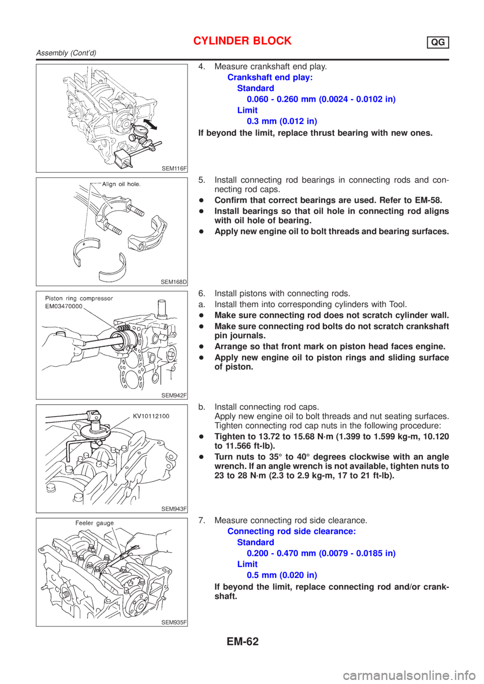
4. Measure crankshaft end play.
Crankshaft end play:
Standard
0.060 - 0.260 mm (0.0024 - 0.0102 in)
Limit
0.3 mm (0.012 in)
If beyond the limit, replace thrust bearing with new ones.
SEM168D
5. Install connecting rod bearings in connecting rods and con-
necting rod caps.
+Confirm that correct bearings are used. Refer to EM-58.
+Install bearings so that oil hole in connecting rod aligns
with oil hole of bearing.
+Apply new engine oil to bolt threads and bearing surfaces.
SEM942F
6. Install pistons with connecting rods.
a. Install them into corresponding cylinders with Tool.
+Make sure connecting rod does not scratch cylinder wall.
+Make sure connecting rod bolts do not scratch crankshaft
pin journals.
+Arrange so that front mark on piston head faces engine.
+Apply new engine oil to piston rings and sliding surface
of piston.
SEM943F
b. Install connecting rod caps.
Apply new engine oil to bolt threads and nut seating surfaces.
Tighten connecting rod cap nuts in the following procedure:
+Tighten to 13.72 to 15.68 N´m (1.399 to 1.599 kg-m, 10.120
to 11.566 ft-lb).
+Turn nuts to 35É to 40É degrees clockwise with an angle
wrench. If an angle wrench is not available, tighten nuts to
23 to 28 N´m (2.3 to 2.9 kg-m, 17 to 21 ft-lb).
SEM935F
7. Measure connecting rod side clearance.
Connecting rod side clearance:
Standard
0.200 - 0.470 mm (0.0079 - 0.0185 in)
Limit
0.5 mm (0.020 in)
If beyond the limit, replace connecting rod and/or crank-
shaft.
CYLINDER BLOCKQG
Assembly (Cont'd)
EM-62
Page 2357 of 3051
SEM982CA
24. Remove timing chain guides.
SEM034G
25. Remove camshaft sprockets.
+For retiming, apply paint mark to timing chain matched
with mating marks of camshaft sprockets.
26. Remove timing chain and crankshaft sprocket.
SEM984C
InspectionNLEM0127Check for cracks and excessive wear at roller links. Replace
chain if necessary.
SEM470E
InstallationNLEM01281. Install crankshaft sprocket on crankshaft.
+Make sure mating marks on crankshaft sprocket face front
of engine.
SEM985C
2. Position crankshaft so that No. 1 piston is set at TDC and key
way is at 12 oclock. Fit timing chain on crankshaft sprocket,
aligning the mating marks.
TIMING CHAINSR
Removal (Cont'd)
EM-100
Page 2381 of 3051
SEM390G
SEM877A
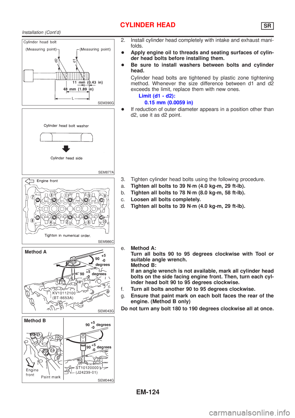
2. Install cylinder head completely with intake and exhaust mani-
folds.
+Apply engine oil to threads and seating surfaces of cylin-
der head bolts before installing them.
+Be sure to install washers between bolts and cylinder
head.
Cylinder head bolts are tightened by plastic zone tightening
method. Whenever the size difference between d1 and d2
exceeds the limit, replace them with new ones.
Limit (d1 - d2):
0.15 mm (0.0059 in)
+If reduction of outer diameter appears in a position other than
d2, use it as d2 point.
SEM986C
3. Tighten cylinder head bolts using the following procedure.
a.Tighten all bolts to 39 N´m (4.0 kg-m, 29 ft-lb).
b.Tighten all bolts to 78 N´m (8.0 kg-m, 58 ft-lb).
c.Loosen all bolts completely.
d.Tighten all bolts to 39 N´m (4.0 kg-m, 29 ft-lb).
SEM043G
SEM044G
e.Method A:
Turn all bolts 90 to 95 degrees clockwise with Tool or
suitable angle wrench.
Method B:
If an angle wrench is not available, mark all cylinder head
bolts on the side facing engine front. Then, turn each cyl-
inder head bolt 90 to 95 degrees clockwise.
f.Turn all bolts another 90 to 95 degrees clockwise.
g.Ensure that paint mark on each bolt faces the rear of the
engine. (Method B only)
Do not turn any bolt 180 to 190 degrees clockwise all at once.
CYLINDER HEADSR
Installation (Cont'd)
EM-124
Page 2382 of 3051
AEM113
Tightening torque N´m (kg-m, ft-lb)
a. 39 (4.0, 29)
b. 78 (8.0, 58)
c. 0 (0, 0)
d. 39 (4.0, 29)
e. 90 - 95 degrees (90 degrees preferred)
f. 90 - 95 degrees (90 degrees preferred)
SEM037G
4. Install cylinder head outside bolts.
5. Install the following water hoses:
+Water hose for cylinder block.
+Water hoses for heater.
SEM036G
6. Install starter motor.
BEM004
7. Remove old liquid gasket from mating surface of LH camshaft
end bracket.
+Also remove old liquid gasket from mating surface of cyl-
inder head.
8. Apply liquid gasket to mating surface of LH camshaft end
bracket as shown in illustration.
+Use Genuine RTV silicone sealant part No. 999MP-A7007
or equivalent.
SEM045G
9. Install camshafts, camshaft brackets.
+Position camshaft.
+LH camshaft key at about 12 o'clock.
+RH camshaft key at about 10 o'clock.
Apply new engine oil to bearing and cam surfaces of cam-
shafts before installing them.
CYLINDER HEADSR
Installation (Cont'd)
EM-125
Page 2400 of 3051
SEM160B
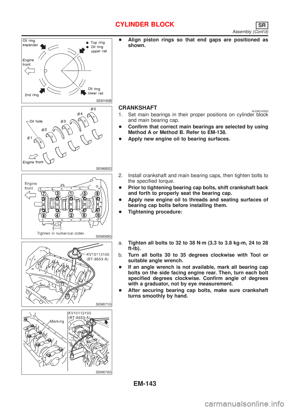
+Align piston rings so that end gaps are positioned as
shown.
SEM685D
CRANKSHAFTNLEM0142S021. Set main bearings in their proper positions on cylinder block
and main bearing cap.
+Confirm that correct main bearings are selected by using
Method A or Method B. Refer to EM-138.
+Apply new engine oil to bearing surfaces.
SEM069G
2. Install crankshaft and main bearing caps, then tighten bolts to
the specified torque.
+Prior to tightening bearing cap bolts, shift crankshaft back
and forth to properly seat the bearing cap.
+Apply new engine oil to threads and seating surfaces of
bearing cap bolts before installing them.
+Tightening procedure:
SEM071G
SEM072G
a.Tighten all bolts to 32 to 38 N´m (3.3 to 3.8 kg-m, 24 to 28
ft-lb).
b.Turn all bolts 30 to 35 degrees clockwise with Tool or
suitable angle wrench.
+If an angle wrench is not available, mark all bearing cap
bolts on the side facing engine rear. Then, turn each bolt
specified degrees clockwise. Confirm angle of degrees
with a graduator, not by eye measurement.
+After securing bearing cap bolts, make sure crankshaft
turns smoothly by hand.
CYLINDER BLOCKSR
Assembly (Cont'd)
EM-143
Page 2401 of 3051
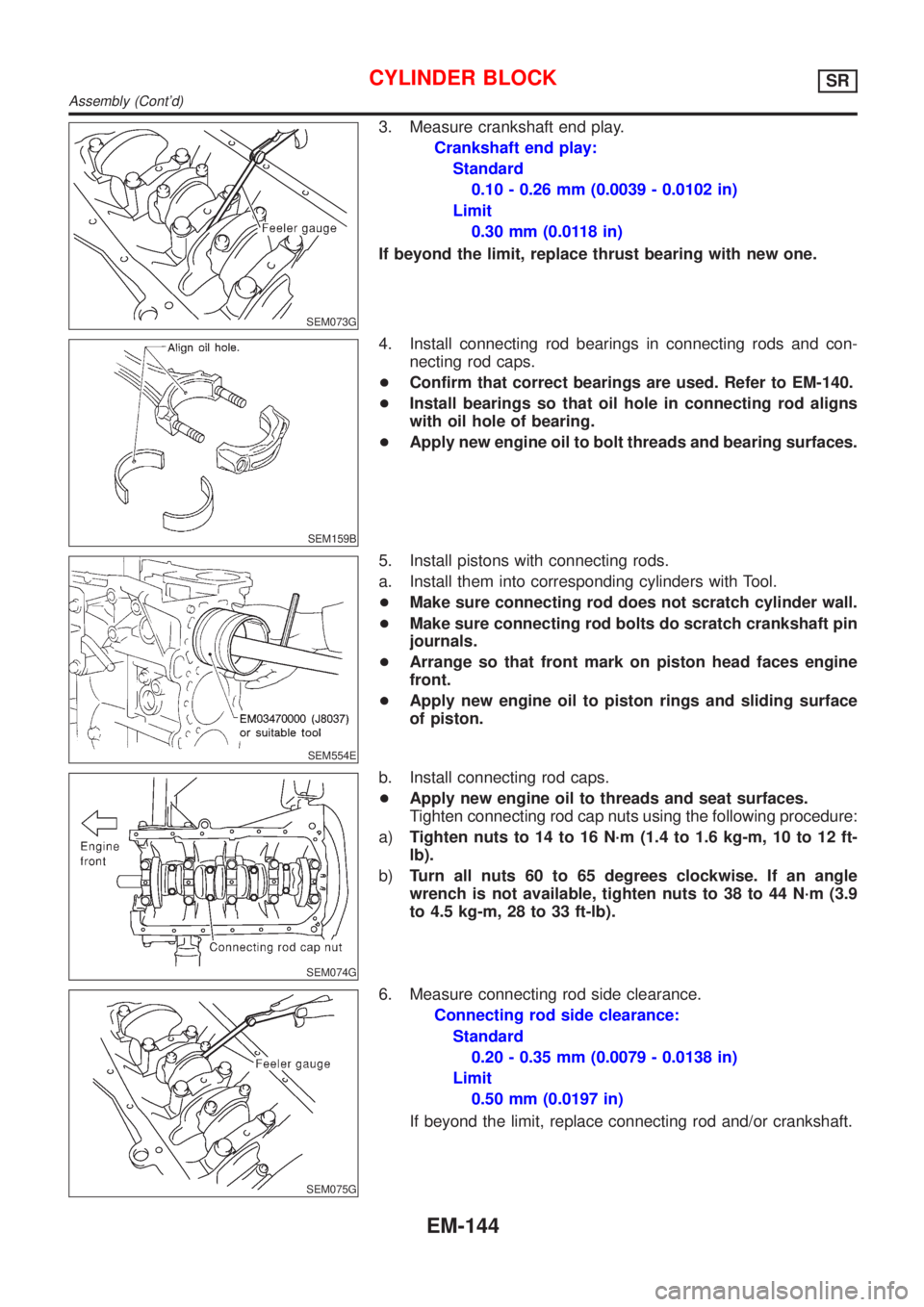
SEM073G
3. Measure crankshaft end play.
Crankshaft end play:
Standard
0.10 - 0.26 mm (0.0039 - 0.0102 in)
Limit
0.30 mm (0.0118 in)
If beyond the limit, replace thrust bearing with new one.
SEM159B
4. Install connecting rod bearings in connecting rods and con-
necting rod caps.
+Confirm that correct bearings are used. Refer to EM-140.
+Install bearings so that oil hole in connecting rod aligns
with oil hole of bearing.
+Apply new engine oil to bolt threads and bearing surfaces.
SEM554E
5. Install pistons with connecting rods.
a. Install them into corresponding cylinders with Tool.
+Make sure connecting rod does not scratch cylinder wall.
+Make sure connecting rod bolts do scratch crankshaft pin
journals.
+Arrange so that front mark on piston head faces engine
front.
+Apply new engine oil to piston rings and sliding surface
of piston.
SEM074G
b. Install connecting rod caps.
+Apply new engine oil to threads and seat surfaces.
Tighten connecting rod cap nuts using the following procedure:
a)Tighten nuts to 14 to 16 N´m (1.4 to 1.6 kg-m, 10 to 12 ft-
lb).
b)Turn all nuts 60 to 65 degrees clockwise. If an angle
wrench is not available, tighten nuts to 38 to 44 N´m (3.9
to 4.5 kg-m, 28 to 33 ft-lb).
SEM075G
6. Measure connecting rod side clearance.
Connecting rod side clearance:
Standard
0.20 - 0.35 mm (0.0079 - 0.0138 in)
Limit
0.50 mm (0.0197 in)
If beyond the limit, replace connecting rod and/or crankshaft.
CYLINDER BLOCKSR
Assembly (Cont'd)
EM-144