2001 NISSAN ALMERA TINO air condition
[x] Cancel search: air conditionPage 275 of 3051
NBR427
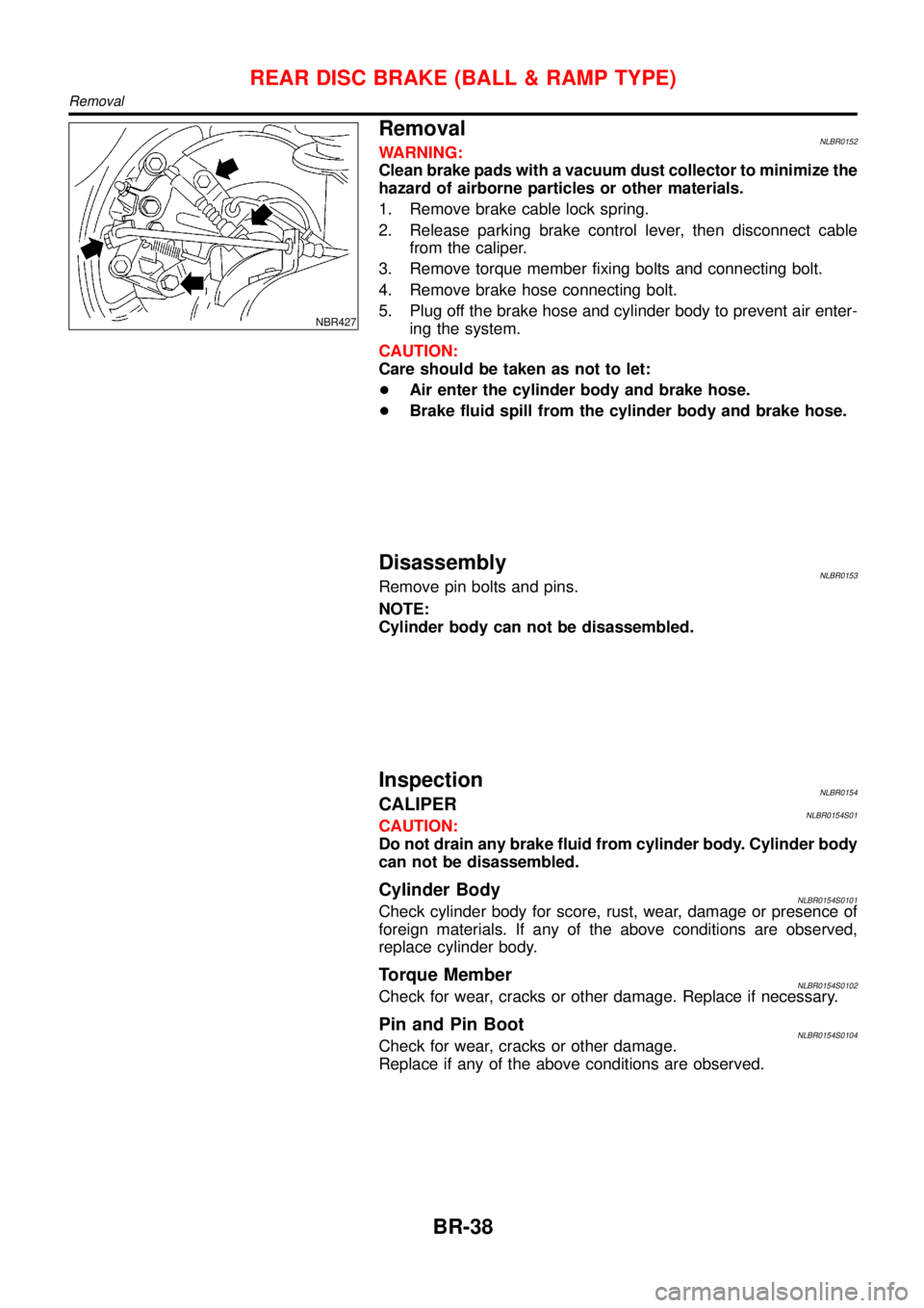
RemovalNLBR0152WARNING:
Clean brake pads with a vacuum dust collector to minimize the
hazard of airborne particles or other materials.
1. Remove brake cable lock spring.
2. Release parking brake control lever, then disconnect cable
from the caliper.
3. Remove torque member fixing bolts and connecting bolt.
4. Remove brake hose connecting bolt.
5. Plug off the brake hose and cylinder body to prevent air enter-
ing the system.
CAUTION:
Care should be taken as not to let:
+Air enter the cylinder body and brake hose.
+Brake fluid spill from the cylinder body and brake hose.
DisassemblyNLBR0153Remove pin bolts and pins.
NOTE:
Cylinder body can not be disassembled.
InspectionNLBR0154CALIPERNLBR0154S01CAUTION:
Do not drain any brake fluid from cylinder body. Cylinder body
can not be disassembled.
Cylinder BodyNLBR0154S0101Check cylinder body for score, rust, wear, damage or presence of
foreign materials. If any of the above conditions are observed,
replace cylinder body.
Torque MemberNLBR0154S0102Check for wear, cracks or other damage. Replace if necessary.
Pin and Pin BootNLBR0154S0104Check for wear, cracks or other damage.
Replace if any of the above conditions are observed.
REAR DISC BRAKE (BALL & RAMP TYPE)
Removal
BR-38
Page 301 of 3051

SEF233G
SEF234G
How to Perform Trouble Diagnoses for Quick
and Accurate Repair
NLBR0094INTRODUCTIONNLBR0094S01The ABS system has an electronic control unit to control major
functions. The control unit accepts input signals from sensors and
instantly drives actuator. It is essential that both kinds of signals are
proper and stable. It is also important to check for conventional
problems: such as air leaks in the booster or lines, lack of brake
fluid, or other problems with the brake system.
It is much more difficult to diagnose a problem that occurs intermit-
tently rather than continuously. Most intermittent problems are
caused by poor electric connections or faulty wiring. In this case,
careful checking of suspicious circuits may help prevent the
replacement of good parts.
A visual check only may not find the cause of the problems, so a
road test should be performed.
Before undertaking actual checks, take just a few minutes to talk
with a customer who approaches with a ABS complaint. The cus-
tomer is a very good source of information on such problems;
especially intermittent ones. Through the talks with the customer,
find out what symptoms are present and under what conditions
they occur.
Start your diagnosis by looking for“conventional”problems first.
This is one of the best ways to troubleshoot brake problems on an
ABS controlled vehicle. Also check related Service Bulletins for
information.
TROUBLE DIAGNOSIS—INTRODUCTIONABS
How to Perform Trouble Diagnoses for Quick and Accurate Repair
BR-64
Page 322 of 3051
5. Pedal Vibration and Noise=NLBR0108
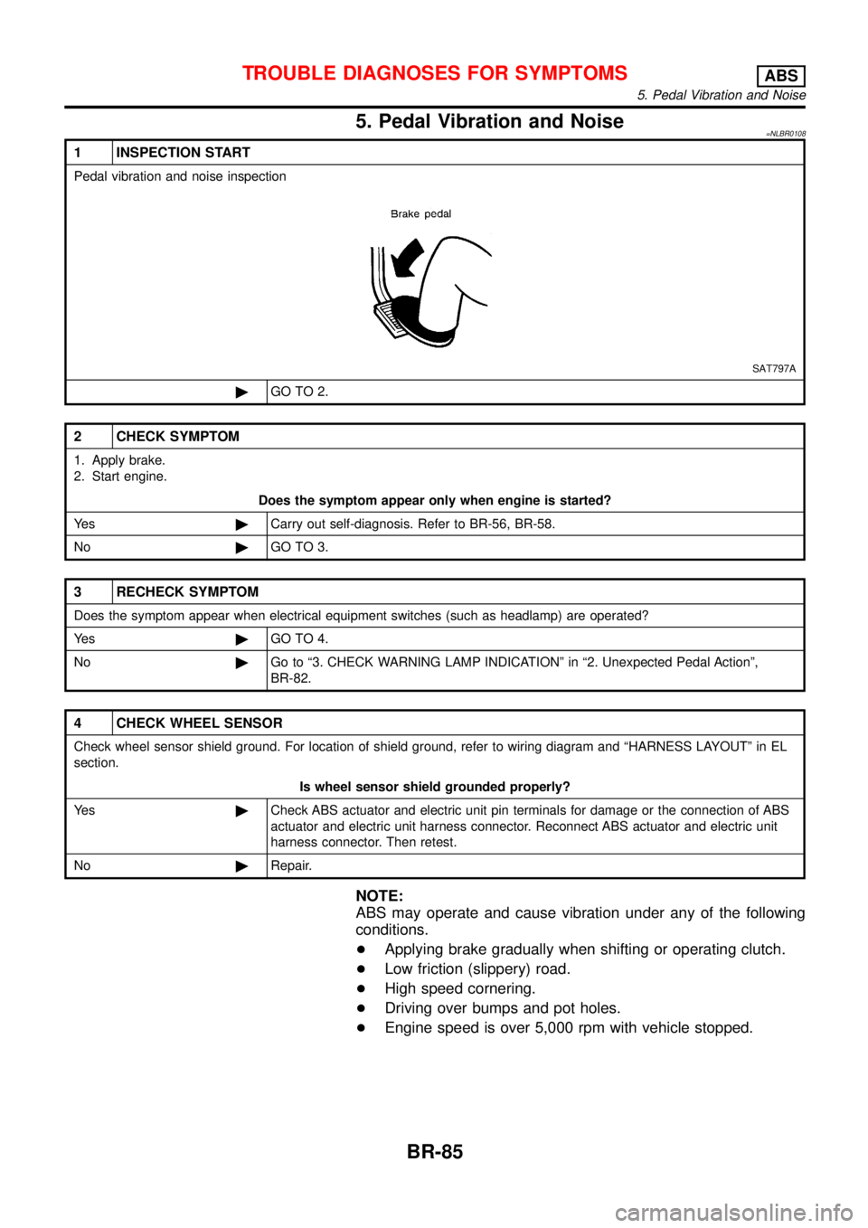
1 INSPECTION START
Pedal vibration and noise inspection
SAT797A
©GO TO 2.
2 CHECK SYMPTOM
1. Apply brake.
2. Start engine.
Does the symptom appear only when engine is started?
Ye s©Carry out self-diagnosis. Refer to BR-56, BR-58.
No©GO TO 3.
3 RECHECK SYMPTOM
Does the symptom appear when electrical equipment switches (such as headlamp) are operated?
Ye s©GO TO 4.
No©Go to“3. CHECK WARNING LAMP INDICATION”in“2. Unexpected Pedal Action”,
BR-82.
4 CHECK WHEEL SENSOR
Check wheel sensor shield ground. For location of shield ground, refer to wiring diagram and“HARNESS LAYOUT”in EL
section.
Is wheel sensor shield grounded properly?
Ye s©Check ABS actuator and electric unit pin terminals for damage or the connection of ABS
actuator and electric unit harness connector. Reconnect ABS actuator and electric unit
harness connector. Then retest.
No©Repair.
NOTE:
ABS may operate and cause vibration under any of the following
conditions.
+Applying brake gradually when shifting or operating clutch.
+Low friction (slippery) road.
+High speed cornering.
+Driving over bumps and pot holes.
+Engine speed is over 5,000 rpm with vehicle stopped.
TROUBLE DIAGNOSES FOR SYMPTOMSABS
5. Pedal Vibration and Noise
BR-85
Page 332 of 3051
BODY & TRIM
SECTION
BT
CONTENTS
PRECAUTIONS...............................................................3
Service Notice..............................................................3
Supplemental Restraint System (SRS)²AIR
BAG²and²SEAT BELT PRE-TENSIONER²...............3
CLIP AND FASTENER....................................................4
Description ...................................................................4
CHASSIS AND BODY MAINTENANCE.........................6
Checking Body Corrosion ............................................6
BODY FRONT END.........................................................7
Removal and Installation .............................................7
FRONT BUMPER ASSEMBLY....................................7
BODY REAR END AND OPENER................................10
Removal and Installation ...........................................10
REAR BUMPER ASSEMBLY....................................10
DOOR.............................................................................13
Adjustment .................................................................13
STRIKER ADJUSTMENT..........................................13
Front Door Glass .......................................................14
FRONT DOOR GLASS AND REGULATOR................14
Front Door Limit Switch Reset (Driver side only)......15
RESET CONDITIONS..............................................15
RESET PROCEDURES............................................15
Rear Door Glass ........................................................16
REAR DOOR GLASS AND REGULATOR..................16
Front Door Lock .........................................................18
OUTSIDE HANDLE ROD ADJUSTMENT...................18
REMOVAL...............................................................18
Rear Door Lock .........................................................20
OUTSIDE HANDLE ROD ADJUSTMENT...................20
REMOVAL...............................................................21
INSTRUMENT PANEL ASSEMBLY.............................22
Removal and Installation ...........................................22
SIDE AND FLOOR TRIM...............................................28
Removal and Installation ...........................................28
LUGGAGE ROOM TRIM...............................................31
Removal and Installation ...........................................31
DOOR TRIM...................................................................32
Removal and Installation ...........................................32ROOF TRIM...................................................................35
Removal and Installation ...........................................35
BACK DOOR TRIM.......................................................37
Removal and Installation ...........................................37
EXTERIOR.....................................................................38
Removal and Installation ...........................................38
FRONT SEAT................................................................46
Removal and Installation ...........................................46
MANUAL SEAT........................................................47
Heated Seat ...............................................................48
Active Head Restraint ................................................48
OPERATION OUTLINE............................................48
REAR SEAT...................................................................49
Removal and Installation ...........................................49
REAR OUTSIDE SEAT.............................................49
REAR CENTER SEAT..............................................50
SUNROOF......................................................................51
Adjustment .................................................................51
Removal .....................................................................51
Trouble Diagnoses.....................................................55
DIAGNOSTIC TABLE................................................55
WIND DEFLECTOR (WHERE FITTED)......................55
ADJUSTMENT.........................................................56
DRAIN HOSES........................................................57
WEATHERSTRIP.....................................................57
LINK AND WIRE ASSEMBLY....................................58
WINDSHIELD AND WINDOWS....................................59
Removal and Installation ...........................................59
REMOVAL...............................................................59
INSTALLATION........................................................59
WINDSHIELD..........................................................60
SIDE WINDOW........................................................61
BACK DOOR WINDOW............................................62
DOOR MIRROR.............................................................63
Removal and Installation ...........................................63
REAR VIEW MIRROR...................................................64
Removal and Installation ...........................................64
REMOVAL...............................................................64
Page 337 of 3051
Checking Body CorrosionNLBT0033Visually check the body sheet metal panel for corrosion, paint damage (scratches, chipping, rubbing, etc.) or
damage to the anti-corrosion materials. In particular, check the following locations.
Hemmed portion
Hood front end, door lower end, trunk lid rear end, etc.
Panel joint
Side sill of rear fender and center pillar, rear wheel housing of rear fender, around strut tower in engine
compartment, etc.
Panel edge
Trunk lid opening, sunroof opening, fender wheelarch flange, fuel filler lid flange, around holes in panel, etc.
Parts contact
Waist molding, windshield molding, bumper, etc.
Protectors
Damage or condition of mudguard, fender protector, chipping protector, etc.
Anti-corrosion materials
Damage or separation of anti-corrosion materials under the body.
Drain holes
Condition of drain holes at door and side sill.
When repairing corroded areas, refer to the Corrosion Repair Manual.
CHASSIS AND BODY MAINTENANCE
Checking Body Corrosion
BT-6
Page 426 of 3051
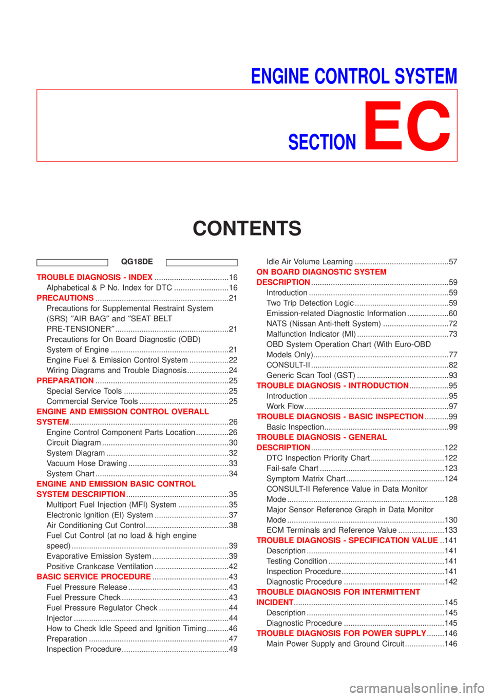
ENGINE CONTROL SYSTEM
SECTION
EC
CONTENTS
QG18DE
TROUBLE DIAGNOSIS - INDEX..................................16
Alphabetical & P No. Index for DTC .........................16
PRECAUTIONS.............................................................21
Precautions for Supplemental Restraint System
(SRS)²AIR BAG²and²SEAT BELT
PRE-TENSIONER²....................................................21
Precautions for On Board Diagnostic (OBD)
System of Engine ......................................................21
Engine Fuel & Emission Control System ..................22
Wiring Diagrams and Trouble Diagnosis ...................24
PREPARATION.............................................................25
Special Service Tools ................................................25
Commercial Service Tools .........................................25
ENGINE AND EMISSION CONTROL OVERALL
SYSTEM.........................................................................26
Engine Control Component Parts Location ...............26
Circuit Diagram ..........................................................30
System Diagram ........................................................32
Vacuum Hose Drawing ..............................................33
System Chart .............................................................34
ENGINE AND EMISSION BASIC CONTROL
SYSTEM DESCRIPTION...............................................35
Multiport Fuel Injection (MFI) System .......................35
Electronic Ignition (EI) System ..................................37
Air Conditioning Cut Control ......................................38
Fuel Cut Control (at no load & high engine
speed) ........................................................................39
Evaporative Emission System ...................................39
Positive Crankcase Ventilation ..................................42
BASIC SERVICE PROCEDURE...................................43
Fuel Pressure Release ..............................................43
Fuel Pressure Check .................................................43
Fuel Pressure Regulator Check ................................44
Injector .......................................................................44
How to Check Idle Speed and Ignition Timing ..........46
Preparation ................................................................47
Inspection Procedure .................................................49Idle Air Volume Learning ...........................................57
ON BOARD DIAGNOSTIC SYSTEM
DESCRIPTION...............................................................59
Introduction ................................................................59
Two Trip Detection Logic ...........................................59
Emission-related Diagnostic Information ...................60
NATS (Nissan Anti-theft System) ..............................72
Malfunction Indicator (MI) ..........................................73
OBD System Operation Chart (With Euro-OBD
Models Only)..............................................................77
CONSULT-II ...............................................................82
Generic Scan Tool (GST) ..........................................93
TROUBLE DIAGNOSIS - INTRODUCTION..................95
Introduction ................................................................95
Work Flow ..................................................................97
TROUBLE DIAGNOSIS - BASIC INSPECTION...........99
Basic Inspection.........................................................99
TROUBLE DIAGNOSIS - GENERAL
DESCRIPTION.............................................................122
DTC Inspection Priority Chart..................................122
Fail-safe Chart .........................................................123
Symptom Matrix Chart .............................................124
CONSULT-II Reference Value in Data Monitor
Mode ........................................................................128
Major Sensor Reference Graph in Data Monitor
Mode ........................................................................130
ECM Terminals and Reference Value .....................133
TROUBLE DIAGNOSIS - SPECIFICATION VALUE..141
Description ...............................................................141
Testing Condition .....................................................141
Inspection Procedure ...............................................141
Diagnostic Procedure ..............................................142
TROUBLE DIAGNOSIS FOR INTERMITTENT
INCIDENT.....................................................................145
Description ...............................................................145
Diagnostic Procedure ..............................................145
TROUBLE DIAGNOSIS FOR POWER SUPPLY........146
Main Power Supply and Ground Circuit ..................146
Page 432 of 3051
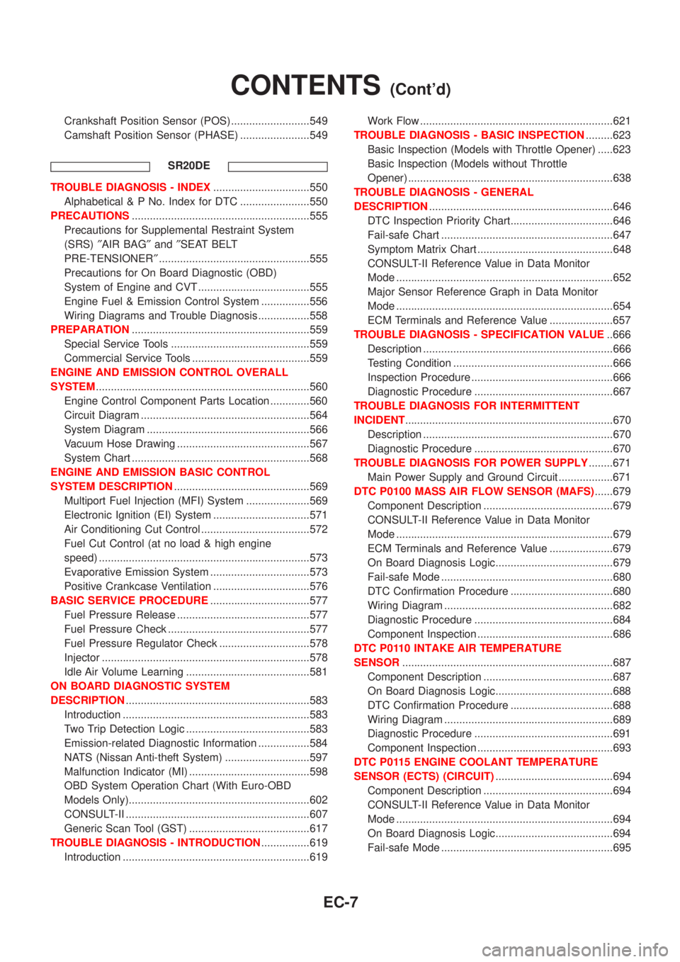
Crankshaft Position Sensor (POS) ..........................549
Camshaft Position Sensor (PHASE) .......................549
SR20DE
TROUBLE DIAGNOSIS - INDEX................................550
Alphabetical & P No. Index for DTC .......................550
PRECAUTIONS...........................................................555
Precautions for Supplemental Restraint System
(SRS)²AIR BAG²and²SEAT BELT
PRE-TENSIONER²..................................................555
Precautions for On Board Diagnostic (OBD)
System of Engine and CVT .....................................555
Engine Fuel & Emission Control System ................556
Wiring Diagrams and Trouble Diagnosis .................558
PREPARATION...........................................................559
Special Service Tools ..............................................559
Commercial Service Tools .......................................559
ENGINE AND EMISSION CONTROL OVERALL
SYSTEM.......................................................................560
Engine Control Component Parts Location .............560
Circuit Diagram ........................................................564
System Diagram ......................................................566
Vacuum Hose Drawing ............................................567
System Chart ...........................................................568
ENGINE AND EMISSION BASIC CONTROL
SYSTEM DESCRIPTION.............................................569
Multiport Fuel Injection (MFI) System .....................569
Electronic Ignition (EI) System ................................571
Air Conditioning Cut Control ....................................572
Fuel Cut Control (at no load & high engine
speed) ......................................................................573
Evaporative Emission System .................................573
Positive Crankcase Ventilation ................................576
BASIC SERVICE PROCEDURE.................................577
Fuel Pressure Release ............................................577
Fuel Pressure Check ...............................................577
Fuel Pressure Regulator Check ..............................578
Injector .....................................................................578
Idle Air Volume Learning .........................................581
ON BOARD DIAGNOSTIC SYSTEM
DESCRIPTION.............................................................583
Introduction ..............................................................583
Two Trip Detection Logic .........................................583
Emission-related Diagnostic Information .................584
NATS (Nissan Anti-theft System) ............................597
Malfunction Indicator (MI) ........................................598
OBD System Operation Chart (With Euro-OBD
Models Only)............................................................602
CONSULT-II .............................................................607
Generic Scan Tool (GST) ........................................617
TROUBLE DIAGNOSIS - INTRODUCTION................619
Introduction ..............................................................619Work Flow ................................................................621
TROUBLE DIAGNOSIS - BASIC INSPECTION.........623
Basic Inspection (Models with Throttle Opener) .....623
Basic Inspection (Models without Throttle
Opener) ....................................................................638
TROUBLE DIAGNOSIS - GENERAL
DESCRIPTION.............................................................646
DTC Inspection Priority Chart..................................646
Fail-safe Chart .........................................................647
Symptom Matrix Chart .............................................648
CONSULT-II Reference Value in Data Monitor
Mode ........................................................................652
Major Sensor Reference Graph in Data Monitor
Mode ........................................................................654
ECM Terminals and Reference Value .....................657
TROUBLE DIAGNOSIS - SPECIFICATION VALUE..666
Description ...............................................................666
Testing Condition .....................................................666
Inspection Procedure ...............................................666
Diagnostic Procedure ..............................................667
TROUBLE DIAGNOSIS FOR INTERMITTENT
INCIDENT.....................................................................670
Description ...............................................................670
Diagnostic Procedure ..............................................670
TROUBLE DIAGNOSIS FOR POWER SUPPLY........671
Main Power Supply and Ground Circuit ..................671
DTC P0100 MASS AIR FLOW SENSOR (MAFS)......679
Component Description ...........................................679
CONSULT-II Reference Value in Data Monitor
Mode ........................................................................679
ECM Terminals and Reference Value .....................679
On Board Diagnosis Logic.......................................679
Fail-safe Mode .........................................................680
DTC Confirmation Procedure ..................................680
Wiring Diagram ........................................................682
Diagnostic Procedure ..............................................684
Component Inspection .............................................686
DTC P0110 INTAKE AIR TEMPERATURE
SENSOR......................................................................687
Component Description ...........................................687
On Board Diagnosis Logic.......................................688
DTC Confirmation Procedure ..................................688
Wiring Diagram ........................................................689
Diagnostic Procedure ..............................................691
Component Inspection .............................................693
DTC P0115 ENGINE COOLANT TEMPERATURE
SENSOR (ECTS) (CIRCUIT).......................................694
Component Description ...........................................694
CONSULT-II Reference Value in Data Monitor
Mode ........................................................................694
On Board Diagnosis Logic.......................................694
Fail-safe Mode .........................................................695
CONTENTS(Cont'd)
EC-7
Page 437 of 3051
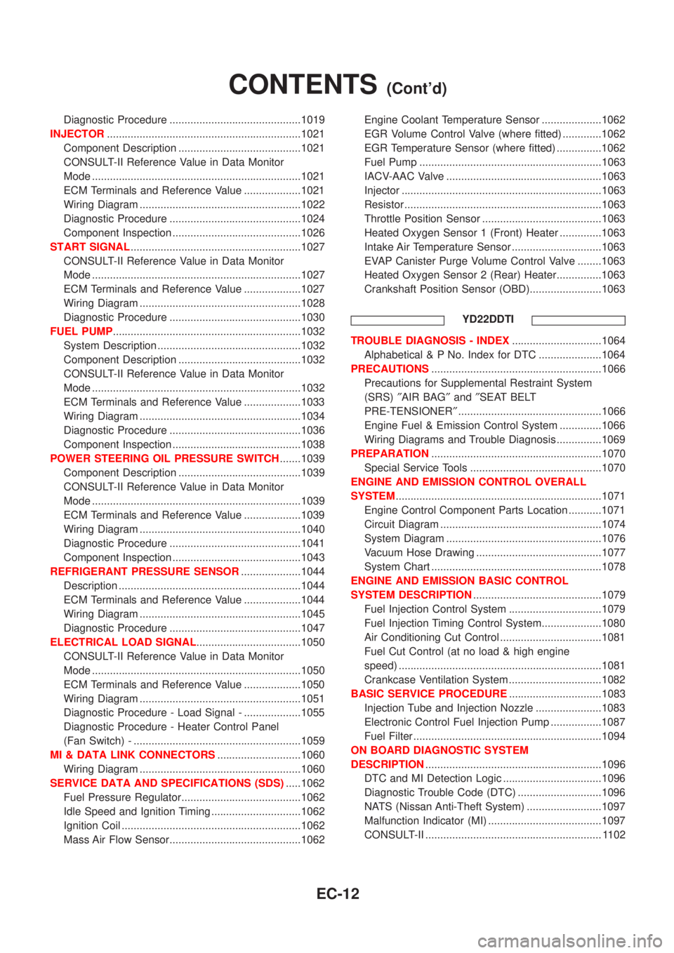
Diagnostic Procedure ............................................1019
INJECTOR.................................................................1021
Component Description .........................................1021
CONSULT-II Reference Value in Data Monitor
Mode ......................................................................1021
ECM Terminals and Reference Value ...................1021
Wiring Diagram ......................................................1022
Diagnostic Procedure ............................................1024
Component Inspection ...........................................1026
START SIGNAL.........................................................1027
CONSULT-II Reference Value in Data Monitor
Mode ......................................................................1027
ECM Terminals and Reference Value ...................1027
Wiring Diagram ......................................................1028
Diagnostic Procedure ............................................1030
FUEL PUMP...............................................................1032
System Description ................................................1032
Component Description .........................................1032
CONSULT-II Reference Value in Data Monitor
Mode ......................................................................1032
ECM Terminals and Reference Value ...................1033
Wiring Diagram ......................................................1034
Diagnostic Procedure ............................................1036
Component Inspection ...........................................1038
POWER STEERING OIL PRESSURE SWITCH.......1039
Component Description .........................................1039
CONSULT-II Reference Value in Data Monitor
Mode ......................................................................1039
ECM Terminals and Reference Value ...................1039
Wiring Diagram ......................................................1040
Diagnostic Procedure ............................................1041
Component Inspection ...........................................1043
REFRIGERANT PRESSURE SENSOR....................1044
Description .............................................................1044
ECM Terminals and Reference Value ...................1044
Wiring Diagram ......................................................1045
Diagnostic Procedure ............................................1047
ELECTRICAL LOAD SIGNAL...................................1050
CONSULT-II Reference Value in Data Monitor
Mode ......................................................................1050
ECM Terminals and Reference Value ...................1050
Wiring Diagram ......................................................1051
Diagnostic Procedure - Load Signal - ...................1055
Diagnostic Procedure - Heater Control Panel
(Fan Switch) - ........................................................1059
MI & DATA LINK CONNECTORS............................1060
Wiring Diagram ......................................................1060
SERVICE DATA AND SPECIFICATIONS (SDS).....1062
Fuel Pressure Regulator........................................1062
Idle Speed and Ignition Timing ..............................1062
Ignition Coil ............................................................1062
Mass Air Flow Sensor............................................1062Engine Coolant Temperature Sensor ....................1062
EGR Volume Control Valve (where fitted) .............1062
EGR Temperature Sensor (where fitted) ...............1062
Fuel Pump .............................................................1063
IACV-AAC Valve ....................................................1063
Injector ...................................................................1063
Resistor ..................................................................1063
Throttle Position Sensor ........................................1063
Heated Oxygen Sensor 1 (Front) Heater ..............1063
Intake Air Temperature Sensor ..............................1063
EVAP Canister Purge Volume Control Valve ........1063
Heated Oxygen Sensor 2 (Rear) Heater...............1063
Crankshaft Position Sensor (OBD)........................1063
YD22DDTI
TROUBLE DIAGNOSIS - INDEX..............................1064
Alphabetical & P No. Index for DTC .....................1064
PRECAUTIONS.........................................................1066
Precautions for Supplemental Restraint System
(SRS)²AIR BAG²and²SEAT BELT
PRE-TENSIONER²................................................1066
Engine Fuel & Emission Control System ..............1066
Wiring Diagrams and Trouble Diagnosis ...............1069
PREPARATION.........................................................1070
Special Service Tools ............................................1070
ENGINE AND EMISSION CONTROL OVERALL
SYSTEM.....................................................................1071
Engine Control Component Parts Location ...........1071
Circuit Diagram ......................................................1074
System Diagram ....................................................1076
Vacuum Hose Drawing ..........................................1077
System Chart .........................................................1078
ENGINE AND EMISSION BASIC CONTROL
SYSTEM DESCRIPTION...........................................1079
Fuel Injection Control System ...............................1079
Fuel Injection Timing Control System....................1080
Air Conditioning Cut Control ..................................1081
Fuel Cut Control (at no load & high engine
speed) ....................................................................1081
Crankcase Ventilation System ...............................1082
BASIC SERVICE PROCEDURE...............................1083
Injection Tube and Injection Nozzle ......................1083
Electronic Control Fuel Injection Pump .................1087
Fuel Filter ...............................................................1094
ON BOARD DIAGNOSTIC SYSTEM
DESCRIPTION...........................................................1096
DTC and MI Detection Logic .................................1096
Diagnostic Trouble Code (DTC) ............................1096
NATS (Nissan Anti-Theft System) .........................1097
Malfunction Indicator (MI) ......................................1097
CONSULT-II ........................................................... 1102
CONTENTS(Cont'd)
EC-12