2001 NISSAN ALMERA TINO air condition
[x] Cancel search: air conditionPage 439 of 3051
On Board Diagnosis Logic.....................................1219
DTC Confirmation Procedure ................................1219
Wiring Diagram ......................................................1221
Diagnostic Procedure ............................................1223
DTC P1251 P4.SPILL/V CIRC..................................1225
Description .............................................................1225
CONSULT-II Reference Value in Data Monitor
Mode ......................................................................1225
ECM Terminals and Reference Value ...................1226
On Board Diagnosis Logic.....................................1226
DTC Confirmation Procedure ................................1226
Wiring Diagram ......................................................1228
Diagnostic Procedure ............................................1230
DTC P1337 P2.DTC PULSE SIG..............................1232
Description .............................................................1232
CONSULT-II Reference Value in Data Monitor
Mode ......................................................................1232
ECM Terminals and Reference Value ...................1233
On Board Diagnosis Logic.....................................1233
DTC Confirmation Procedure ................................1233
Wiring Diagram ......................................................1235
Diagnostic Procedure ............................................1237
DTC P1341 P1.CAM POS SEN................................1239
Description .............................................................1239
CONSULT-II Reference Value in Data Monitor
Mode ......................................................................1239
ECM Terminals and Reference Value ...................1240
On Board Diagnosis Logic.....................................1240
DTC Confirmation Procedure ................................1240
Wiring Diagram ......................................................1242
Diagnostic Procedure ............................................1244
DTC P1600 P3.PUMP COMM LINE..........................1246
Description .............................................................1246
CONSULT-II Reference Value in Data Monitor
Mode ......................................................................1246
ECM Terminals and Reference Value ...................1247
On Board Diagnosis Logic.....................................1247
DTC Confirmation Procedure ................................1247
Wiring Diagram ......................................................1249
Diagnostic Procedure ............................................1251
DTC P1603 ECM 12, DTC P1607 ECM 2.................1253
Description .............................................................1253
On Board Diagnosis Logic.....................................1253
DTC Confirmation Procedure ................................1253
Diagnostic Procedure ............................................1254
DTC P1620 ECM RLY...............................................1255
ECM Terminals and Reference Value ...................1255
On Board Diagnosis Logic.....................................1255
DTC Confirmation Procedure ................................1255
Wiring Diagram ......................................................1256
Diagnostic Procedure ............................................1258DTC P1621 ECM 15..................................................1260
Description .............................................................1260
On Board Diagnosis Logic.....................................1260
DTC Confirmation Procedure ................................1260
Diagnostic Procedure ............................................1261
DTC P1660 BATTERY VOLTAGE............................1262
On Board Diagnosis Logic.....................................1262
DTC Confirmation Procedure ................................1262
Diagnostic Procedure ............................................1262
DTC P1690 P5.PUMP C/MODULE...........................1264
Description .............................................................1264
CONSULT-II Reference Value in Data Monitor
Mode ......................................................................1264
ECM Terminals and Reference Value ...................1265
On Board Diagnosis Logic.....................................1265
DTC Confirmation Procedure ................................1265
Diagnostic Procedure ............................................1266
GLOW CONTROL SYSTEM.....................................1267
Description .............................................................1267
ECM Terminals and Reference Value ...................1268
Wiring Diagram ......................................................1269
Diagnostic Procedure ............................................1271
EGR VOLUME CONTROL SYSTEM........................1277
Description .............................................................1277
CONSULT-II Reference Value in Data Monitor
Mode ......................................................................1278
ECM Terminals and Reference Value ...................1278
Wiring Diagram ......................................................1279
Diagnostic Procedure ............................................1281
SWIRL CONTROL VALVE CONTROL SOLENOID
VALVE........................................................................1285
Description .............................................................1285
CONSULT-II Reference Value in Data Monitor
Mode ......................................................................1286
ECM Terminals and Reference Value ...................1286
Wiring Diagram ......................................................1287
Diagnostic Procedure ............................................1289
START SIGNAL.........................................................1293
Wiring Diagram ......................................................1293
Diagnostic Procedure ............................................1295
PARK/NEUTRAL POSITION (PNP) SWITCH
(WHERE FITTED)......................................................1297
Description .............................................................1297
CONSULT-II Reference Value in Data Monitor
Mode ......................................................................1297
ECM Terminals and Reference Value ...................1297
Wiring Diagram ......................................................1298
Diagnostic Procedure ............................................1299
AIR CONDITIONER CONTROL................................1301
Wiring Diagram ......................................................1301
MI & DATA LINK CONNECTORS............................1303
Wiring Diagram ......................................................1303
CONTENTS(Cont'd)
EC-14
Page 442 of 3051
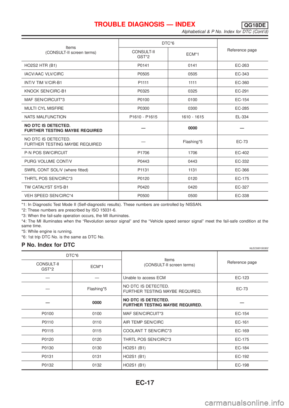
Items
(CONSULT-II screen terms)DTC*6
Reference page
CONSULT-II
GST*2ECM*1
HO2S2 HTR (B1) P0141 0141 EC-263
IACV/AAC VLV/CIRC P0505 0505 EC-343
INT/V TIM V/CIR-B1 P1111 1111EC-360
KNOCK SEN/CIRC-B1 P0325 0325 EC-291
MAF SEN/CIRCUIT*3 P0100 0100 EC-154
MULTI CYL MISFIRE P0300 0300 EC-285
NATS MALFUNCTION P1610 - P1615 1610 - 1615 EL-334
NO DTC IS DETECTED.
FURTHER TESTING MAYBE REQUIREDÐ 0000 Ð
NO DTC IS DETECTED.
FURTHER TESTING MAYBE REQUIREDÐ Flashing*5 EC-73
P-N POS SW/CIRCUIT P1706 1706 EC-402
PURG VOLUME CONT/V P0443 0443 EC-332
SWRL CONT SOL/V (where fitted) P1131 1131 EC-366
THRTL POS SEN/CIRC*3 P0120 0120 EC-175
TW CATALYST SYS-B1 P0420 0420 EC-327
VEH SPEED SEN/CIRC*4 P0500 0500 EC-338
*1: In Diagnostic Test Mode II (Self-diagnostic results). These numbers are controlled by NISSAN.
*2: These numbers are prescribed by ISO 15031-6.
*3: When the fail-safe operation occurs, the MI illuminates.
*4: The MI illuminates when the ªRevolution sensor signalº and the ªVehicle speed sensor signalº meet the fail-safe condition at the
same time.
*5: While engine is running.
*6: 1st trip DTC No. is the same as DTC No.
P No. Index for DTCNLEC0001S0302
DTC*6
Items
(CONSULT-II screen terms)Reference page
CONSULT-II
GST*2ECM*1
Ð Ð Unable to access ECM EC-123
Ð Flashing*5NO DTC IS DETECTED.
FURTHER TESTING MAYBE REQUIRED.EC-73
Ð 0000NO DTC IS DETECTED.
FURTHER TESTING MAYBE REQUIRED.Ð
P0100 0100 MAF SEN/CIRCUIT*3 EC-154
P0110 0110 AIR TEMP SEN/CIRC EC-161
P0115 0115 COOLANT T SEN/CIRC*3 EC-169
P0120 0120 THRTL POS SEN/CIRC*3 EC-175
P0130 0130 HO2S1 (B1) EC-184
P0131 0131 HO2S1 (B1) EC-192
P0132 0132 HO2S1 (B1) EC-198
TROUBLE DIAGNOSIS Ð INDEXQG18DE
Alphabetical & P No. Index for DTC (Cont'd)
EC-17
Page 459 of 3051
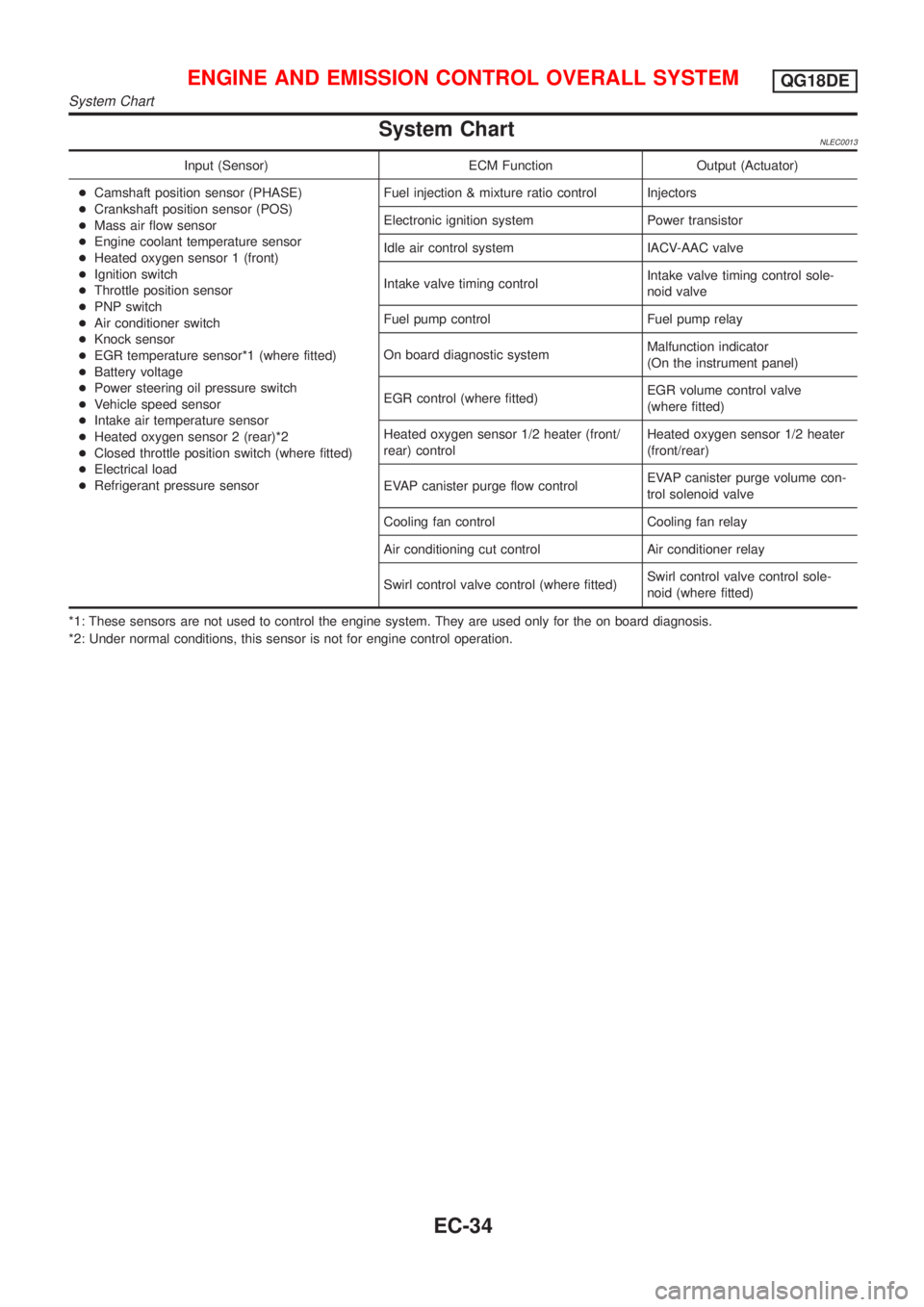
System ChartNLEC0013
Input (Sensor) ECM Function Output (Actuator)
+Camshaft position sensor (PHASE)
+Crankshaft position sensor (POS)
+Mass air flow sensor
+Engine coolant temperature sensor
+Heated oxygen sensor 1 (front)
+Ignition switch
+Throttle position sensor
+PNP switch
+Air conditioner switch
+Knock sensor
+EGR temperature sensor*1 (where fitted)
+Battery voltage
+Power steering oil pressure switch
+Vehicle speed sensor
+Intake air temperature sensor
+Heated oxygen sensor 2 (rear)*2
+Closed throttle position switch (where fitted)
+Electrical load
+Refrigerant pressure sensorFuel injection & mixture ratio control Injectors
Electronic ignition system Power transistor
Idle air control system IACV-AAC valve
Intake valve timing controlIntake valve timing control sole-
noid valve
Fuel pump control Fuel pump relay
On board diagnostic systemMalfunction indicator
(On the instrument panel)
EGR control (where fitted)EGR volume control valve
(where fitted)
Heated oxygen sensor 1/2 heater (front/
rear) controlHeated oxygen sensor 1/2 heater
(front/rear)
EVAP canister purge flow controlEVAP canister purge volume con-
trol solenoid valve
Cooling fan control Cooling fan relay
Air conditioning cut control Air conditioner relay
Swirl control valve control (where fitted)Swirl control valve control sole-
noid (where fitted)
*1: These sensors are not used to control the engine system. They are used only for the on board diagnosis.
*2: Under normal conditions, this sensor is not for engine control operation.
ENGINE AND EMISSION CONTROL OVERALL SYSTEMQG18DE
System Chart
EC-34
Page 460 of 3051
Multiport Fuel Injection (MFI) System
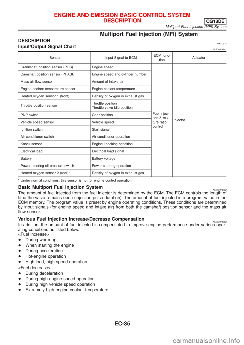
DESCRIPTIONNLEC0014Input/Output Signal ChartNLEC0014S01
Sensor Input Signal to ECMECM func-
tionActuator
Crankshaft position sensor (POS) Engine speed
Fuel injec-
tion & mix-
ture ratio
controlInjector Camshaft position sensor (PHASE) Engine speed and cylinder number
Mass air flow sensor Amount of intake air
Engine coolant temperature sensor Engine coolant temperature
Heated oxygen sensor 1 (front) Density of oxygen in exhaust gas
Throttle position sensorThrottle position
Throttle valve idle position
PNP switch Gear position
Vehicle speed sensor Vehicle speed
Ignition switch Start signal
Air conditioner switch Air conditioner operation
Knock sensor Engine knocking condition
Electrical load Electrical load signal
Battery Battery voltage
Power steering oil pressure switch Power steering operation
Heated oxygen sensor 2 (rear)* Density of oxygen in exhaust gas
* Under normal conditions, this sensor is not for engine control operation.
Basic Multiport Fuel Injection SystemNLEC0014S02The amount of fuel injected from the fuel injector is determined by the ECM. The ECM controls the length of
time the valve remains open (injection pulse duration). The amount of fuel injected is a program value in the
ECM memory. The program value is preset by engine operating conditions. These conditions are determined
by input signals (for engine speed and intake air) from both the camshaft position sensor and the mass air
flow sensor.
Various Fuel Injection Increase/Decrease CompensationNLEC0014S03In addition, the amount of fuel injected is compensated to improve engine performance under various oper-
ating conditions as listed below.
+During warm-up
+When starting the engine
+During acceleration
+Hot-engine operation
+High-load, high-speed operation
+During deceleration
+During high engine speed operation
+During high vehicle speed operation
+Extremely high engine coolant temperature
ENGINE AND EMISSION BASIC CONTROL SYSTEM
DESCRIPTION
QG18DE
Multiport Fuel Injection (MFI) System
EC-35
Page 461 of 3051
Mixture Ratio Feedback Control (Closed loop control)NLEC0014S04
SEF336WA
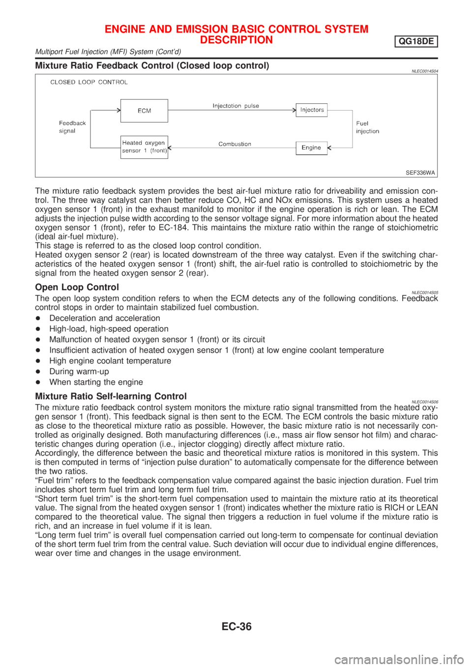
The mixture ratio feedback system provides the best air-fuel mixture ratio for driveability and emission con-
trol. The three way catalyst can then better reduce CO, HC and NOx emissions. This system uses a heated
oxygen sensor 1 (front) in the exhaust manifold to monitor if the engine operation is rich or lean. The ECM
adjusts the injection pulse width according to the sensor voltage signal. For more information about the heated
oxygen sensor 1 (front), refer to EC-184. This maintains the mixture ratio within the range of stoichiometric
(ideal air-fuel mixture).
This stage is referred to as the closed loop control condition.
Heated oxygen sensor 2 (rear) is located downstream of the three way catalyst. Even if the switching char-
acteristics of the heated oxygen sensor 1 (front) shift, the air-fuel ratio is controlled to stoichiometric by the
signal from the heated oxygen sensor 2 (rear).
Open Loop ControlNLEC0014S05The open loop system condition refers to when the ECM detects any of the following conditions. Feedback
control stops in order to maintain stabilized fuel combustion.
+Deceleration and acceleration
+High-load, high-speed operation
+Malfunction of heated oxygen sensor 1 (front) or its circuit
+Insufficient activation of heated oxygen sensor 1 (front) at low engine coolant temperature
+High engine coolant temperature
+During warm-up
+When starting the engine
Mixture Ratio Self-learning ControlNLEC0014S06The mixture ratio feedback control system monitors the mixture ratio signal transmitted from the heated oxy-
gen sensor 1 (front). This feedback signal is then sent to the ECM. The ECM controls the basic mixture ratio
as close to the theoretical mixture ratio as possible. However, the basic mixture ratio is not necessarily con-
trolled as originally designed. Both manufacturing differences (i.e., mass air flow sensor hot film) and charac-
teristic changes during operation (i.e., injector clogging) directly affect mixture ratio.
Accordingly, the difference between the basic and theoretical mixture ratios is monitored in this system. This
is then computed in terms of ªinjection pulse durationº to automatically compensate for the difference between
the two ratios.
ªFuel trimº refers to the feedback compensation value compared against the basic injection duration. Fuel trim
includes short term fuel trim and long term fuel trim.
ªShort term fuel trimº is the short-term fuel compensation used to maintain the mixture ratio at its theoretical
value. The signal from the heated oxygen sensor 1 (front) indicates whether the mixture ratio is RICH or LEAN
compared to the theoretical value. The signal then triggers a reduction in fuel volume if the mixture ratio is
rich, and an increase in fuel volume if it is lean.
ªLong term fuel trimº is overall fuel compensation carried out long-term to compensate for continual deviation
of the short term fuel trim from the central value. Such deviation will occur due to individual engine differences,
wear over time and changes in the usage environment.
ENGINE AND EMISSION BASIC CONTROL SYSTEM
DESCRIPTION
QG18DE
Multiport Fuel Injection (MFI) System (Cont'd)
EC-36
Page 463 of 3051
System DescriptionNLEC0015S02
SEF742M
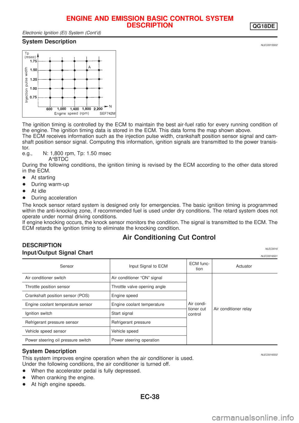
The ignition timing is controlled by the ECM to maintain the best air-fuel ratio for every running condition of
the engine. The ignition timing data is stored in the ECM. This data forms the map shown above.
The ECM receives information such as the injection pulse width, crankshaft position sensor signal and cam-
shaft position sensor signal. Computing this information, ignition signals are transmitted to the power transis-
tor.
e.g., N: 1,800 rpm, Tp: 1.50 msec
AÉBTDC
During the following conditions, the ignition timing is revised by the ECM according to the other data stored
in the ECM.
+At starting
+During warm-up
+At idle
+During acceleration
The knock sensor retard system is designed only for emergencies. The basic ignition timing is programmed
within the anti-knocking zone, if recommended fuel is used under dry conditions. The retard system does not
operate under normal driving conditions.
If engine knocking occurs, the knock sensor monitors the condition. The signal is transmitted to the ECM. The
ECM retards the ignition timing to eliminate the knocking condition.
Air Conditioning Cut Control
DESCRIPTIONNLEC0016Input/Output Signal ChartNLEC0016S01
Sensor Input Signal to ECMECM func-
tionActuator
Air conditioner switch Air conditioner ªONº signal
Air condi-
tioner cut
controlAir conditioner relay Throttle position sensor Throttle valve opening angle
Crankshaft position sensor (POS) Engine speed
Engine coolant temperature sensor Engine coolant temperature
Ignition switch Start signal
Refrigerant pressure sensor Refrigerant pressure
Vehicle speed sensor Vehicle speed
Power steering oil pressure switch Power steering operation
System DescriptionNLEC0016S02This system improves engine operation when the air conditioner is used.
Under the following conditions, the air conditioner is turned off.
+When the accelerator pedal is fully depressed.
+When cranking the engine.
+At high engine speeds.
ENGINE AND EMISSION BASIC CONTROL SYSTEM
DESCRIPTION
QG18DE
Electronic Ignition (EI) System (Cont'd)
EC-38
Page 464 of 3051
+When the engine coolant temperature becomes excessively high.
+When operating power steering during low engine speed or low vehicle speed.
+When engine speed is excessively low.
+When the refrigerant pressure is excessively high or low.
Fuel Cut Control (at no load & high engine
speed)
DESCRIPTIONNLEC0017Input/Output Signal ChartNLEC0017S01
Sensor Input Signal to ECMECM func-
tionActuator
Vehicle speed sensor Vehicle speed
Fuel cut
controlInjectors PNP switch Neutral position
Throttle position sensor Throttle position
Engine coolant temperature sensor Engine coolant temperature
Crankshaft position sensor (POS) Engine speed
Camshaft position sensor (PHASE) Engine speed and cylinder number
If the engine speed is above 3,950 rpm with no load, (for example, in Neutral and engine speed over 4,000
rpm) fuel will be cut off after some time. The exact time when the fuel is cut off varies based on engine speed.
Fuel cut will operate until the engine speed reaches 1,150 rpm, then fuel cut is cancelled.
NOTE:
This function is different from deceleration control listed under ªMultiport Fuel Injection (MFI) Systemº,
EC-35.
Evaporative Emission System
DESCRIPTIONNLEC0018
SEF916WA
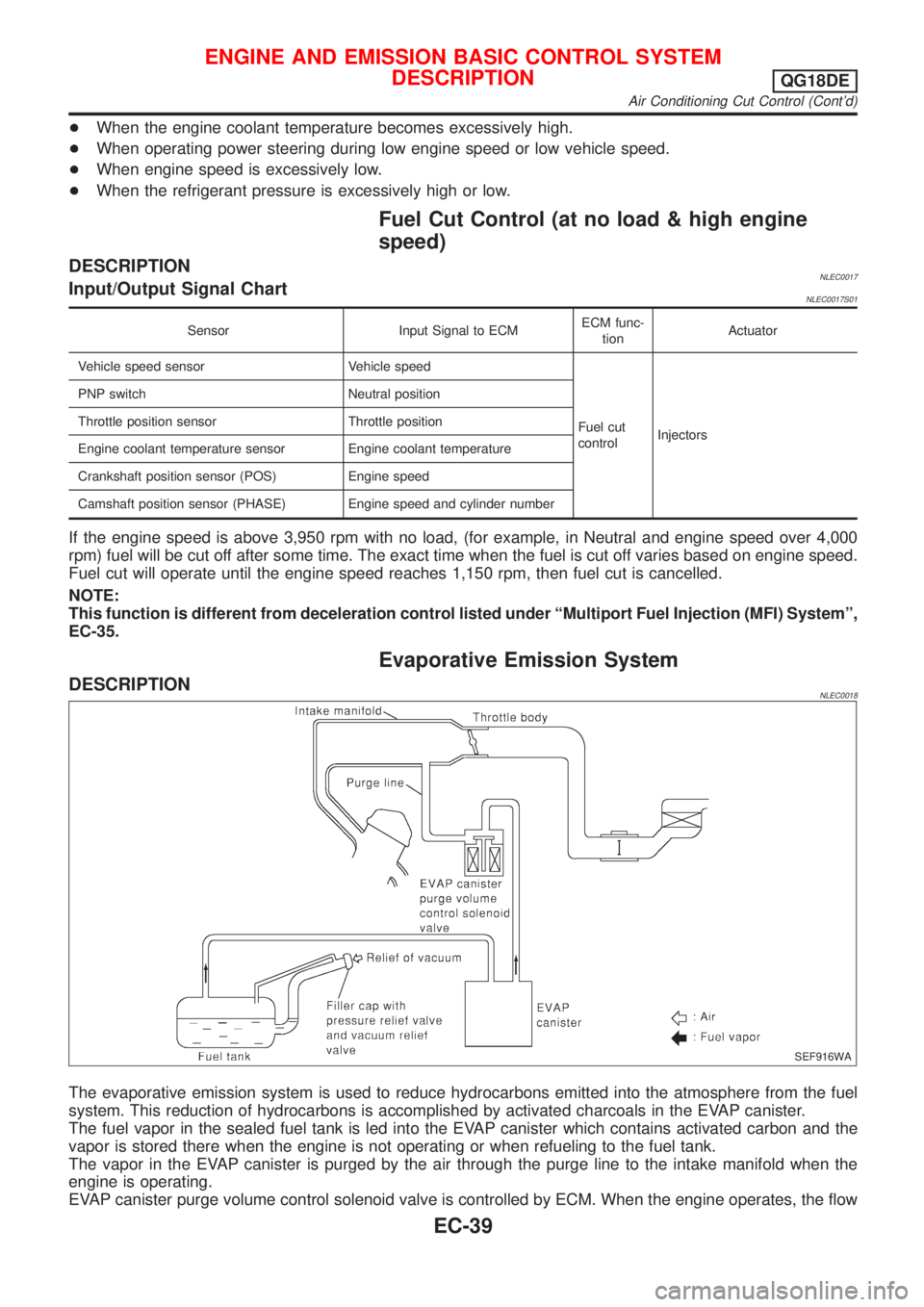
The evaporative emission system is used to reduce hydrocarbons emitted into the atmosphere from the fuel
system. This reduction of hydrocarbons is accomplished by activated charcoals in the EVAP canister.
The fuel vapor in the sealed fuel tank is led into the EVAP canister which contains activated carbon and the
vapor is stored there when the engine is not operating or when refueling to the fuel tank.
The vapor in the EVAP canister is purged by the air through the purge line to the intake manifold when the
engine is operating.
EVAP canister purge volume control solenoid valve is controlled by ECM. When the engine operates, the flow
ENGINE AND EMISSION BASIC CONTROL SYSTEM
DESCRIPTION
QG18DE
Air Conditioning Cut Control (Cont'd)
EC-39
Page 467 of 3051
Positive Crankcase Ventilation
DESCRIPTIONNLEC0022
SEF921W
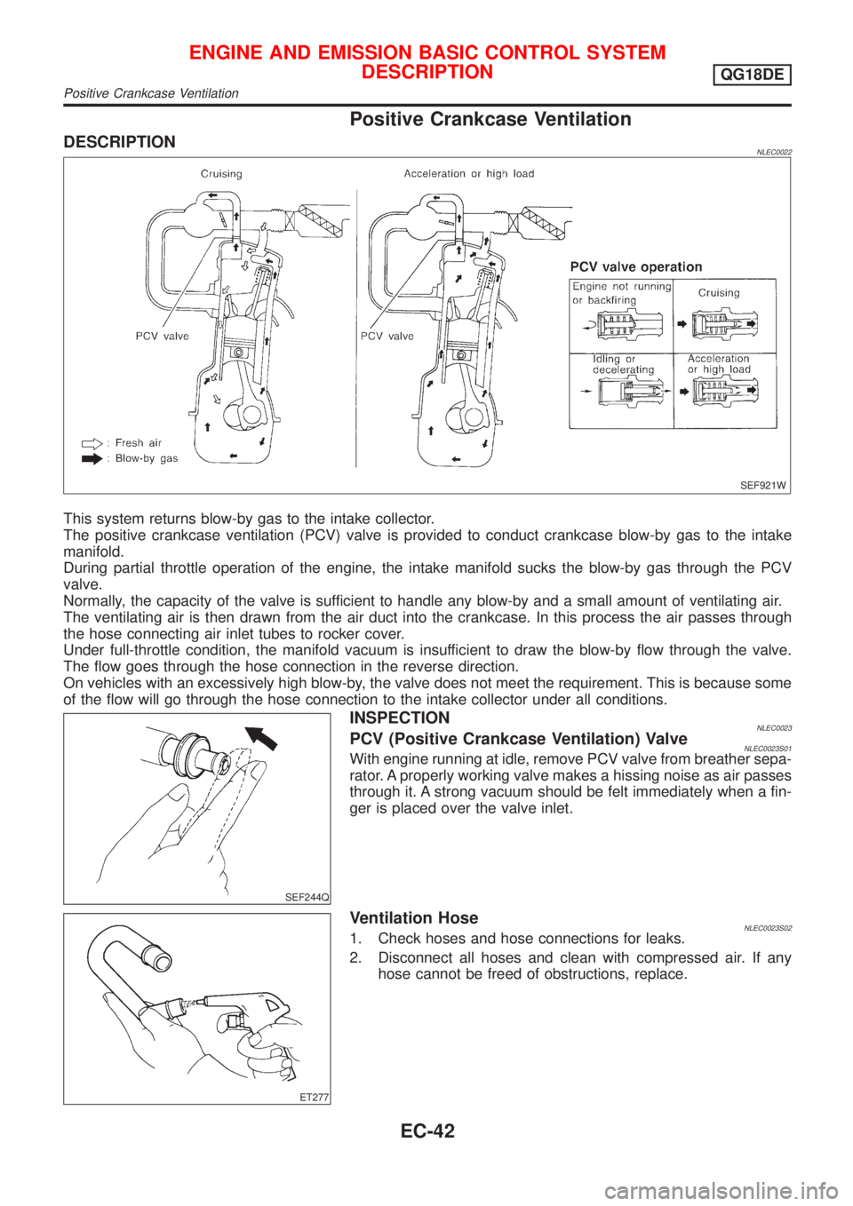
This system returns blow-by gas to the intake collector.
The positive crankcase ventilation (PCV) valve is provided to conduct crankcase blow-by gas to the intake
manifold.
During partial throttle operation of the engine, the intake manifold sucks the blow-by gas through the PCV
valve.
Normally, the capacity of the valve is sufficient to handle any blow-by and a small amount of ventilating air.
The ventilating air is then drawn from the air duct into the crankcase. In this process the air passes through
the hose connecting air inlet tubes to rocker cover.
Under full-throttle condition, the manifold vacuum is insufficient to draw the blow-by flow through the valve.
The flow goes through the hose connection in the reverse direction.
On vehicles with an excessively high blow-by, the valve does not meet the requirement. This is because some
of the flow will go through the hose connection to the intake collector under all conditions.
SEF244Q
INSPECTIONNLEC0023PCV (Positive Crankcase Ventilation) ValveNLEC0023S01With engine running at idle, remove PCV valve from breather sepa-
rator. A properly working valve makes a hissing noise as air passes
through it. A strong vacuum should be felt immediately when a fin-
ger is placed over the valve inlet.
ET277
Ventilation HoseNLEC0023S021. Check hoses and hose connections for leaks.
2. Disconnect all hoses and clean with compressed air. If any
hose cannot be freed of obstructions, replace.
ENGINE AND EMISSION BASIC CONTROL SYSTEM
DESCRIPTION
QG18DE
Positive Crankcase Ventilation
EC-42