2001 NISSAN ALMERA TINO coolant level
[x] Cancel search: coolant levelPage 1628 of 3051
AEC640
SEF111X
SEC163BA
MEC475B
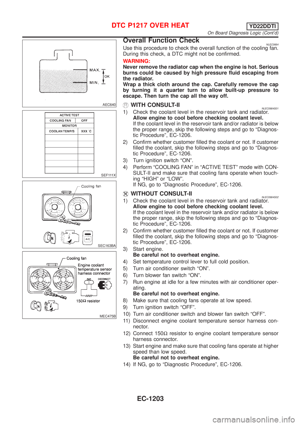
Overall Function CheckNLEC0664Use this procedure to check the overall function of the cooling fan.
During this check, a DTC might not be confirmed.
WARNING:
Never remove the radiator cap when the engine is hot. Serious
burns could be caused by high pressure fluid escaping from
the radiator.
Wrap a thick cloth around the cap. Carefully remove the cap
by turning it a quarter turn to allow built-up pressure to
escape. Then turn the cap all the way off.
WITH CONSULT-IINLEC0664S011) Check the coolant level in the reservoir tank and radiator.
Allow engine to cool before checking coolant level.
If the coolant level in the reservoir tank and/or radiator is below
the proper range, skip the following steps and go to ªDiagnos-
tic Procedureº, EC-1206.
2) Confirm whether customer filled the coolant or not. If customer
filled the coolant, skip the following steps and go to ªDiagnos-
tic Procedureº, EC-1206.
3) Turn ignition switch ªONº.
4) Perform ªCOOLING FANº in ªACTIVE TESTº mode with CON-
SULT-II and make sure that cooling fans operate when touch-
ing ªHIGHº or ªLOWº.
If NG, go to ªDiagnostic Procedureº, EC-1206.
WITHOUT CONSULT-IINLEC0664S021) Check the coolant level in the reservoir tank and radiator.
Allow engine to cool before checking coolant level.
If the coolant level in the reservoir tank and/or radiator is below
the proper range, skip the following steps and go to ªDiagnos-
tic Procedureº, EC-1206.
2) Confirm whether customer filled the coolant or not. If customer
filled the coolant, skip the following steps and go to ªDiagnos-
tic Procedureº, EC-1206.
3) Start engine.
Be careful not to overheat engine.
4) Set temperature control lever to full cold position.
5) Turn air conditioner switch ªONº.
6) Turn blower fan switch ªONº.
7) Run engine at idle for a few minutes with air conditioner oper-
ating.
Be careful not to overheat engine.
8) Make sure that cooling fans operate at low speed.
9) Turn ignition switch ªOFFº.
10) Turn air conditioner switch and blower fan switch ªOFFº.
11) Disconnect engine coolant temperature sensor harness con-
nector.
12) Connect 150Wresistor to engine coolant temperature sensor
harness connector.
13) Start engine and make sure that cooling fans operate at higher
speed than low speed.
Be careful not to overheat engine.
14) If NG, go to ªDiagnostic Procedureº, EC-1206.
DTC P1217 OVER HEATYD22DDTI
On Board Diagnosis Logic (Cont'd)
EC-1203
Page 1642 of 3051

9 CHECK INTERMITTENT INCIDENT
1. Perform ªTROUBLE DIAGNOSIS FOR INTERMITTENT INCIDENTº, EC-1135.
©INSPECTION END
Main 12 Causes of OverheatingNLEC0667
Engine Step Inspection item Equipment Condition Reference page
OFF 1+Blocked radiator
+Blocked radiator grille
+Blocked bumper+Visual No blocking Ð
2+Coolant mixture+Coolant tester 30 - 50% coolant mixture See MA-20, ªRECOM-
MENDED FLUIDS AND
LUBRICANTSº.
3+Coolant level+Visual Coolant up to MAX level
in reservoir tank and
radiator filler neckSee LC-19, ªChanging
Engine Coolantº.
4+Radiator cap+Pressure tester 78 - 98 kPa
(0.78 - 0.98 bar, 0.8 - 1.0
kg/cm
2, 11 - 14 psi)See LC-54, ªSystem
Checkº.
ON*
25+Coolant leaks+Visual No leaks See LC-54, ªSystem
Checkº.
ON*
26+Thermostat+Touch the upper and
lower radiator hosesBoth hoses should be
hotSee LC-57, ªThermostatº
and ªRadiatorº.
ON*
17+Cooling fan+CONSULT-II Operating See Trouble Diagnosis
for DTC P1217,
EC-1201.
OFF 8+Combustion gas leak+Color checker chemi-
cal tester 4 Gas ana-
lyzerNegative Ð
ON*
39+Coolant temperature
gauge+Visual Gauge less than 3/4
when drivingÐ
+Coolant overflow to
reservoir tank+Visual No overflow during driv-
ing and idlingSee LC-59, ªChanging
Engine Coolantº.
OFF*
410+Coolant return from
reservoir tank to radia-
tor+Visual Should be initial level in
reservoir tankSee LC-60, ªREFILLING
ENGINE COOLANTº.
OFF 11+Cylinder head+Straight gauge feeler
gauge0.04mm (0.0016 in)
Maximum distortion
(warping)See EM-203, ªInspec-
tionº.
12+Cylinder block and
pistons+Visual No scuffing on cylinder
walls or pistonSee EM-225, ªInspec-
tionº.
*1: Turn the ignition switch ON.
*2: Engine running at 3,000 rpm for 10 minutes.
*3: Drive at 90 km/h (55 MPH) for 30 minutes and then let idle for 10 minutes.
*4: After 60 minutes of cool down time.
For more information, refer to LC-62, ªOVERHEATING CAUSE ANALYSISº.
DTC P1217 OVER HEATYD22DDTI
Diagnostic Procedure (Cont'd)
EC-1217
Page 1803 of 3051
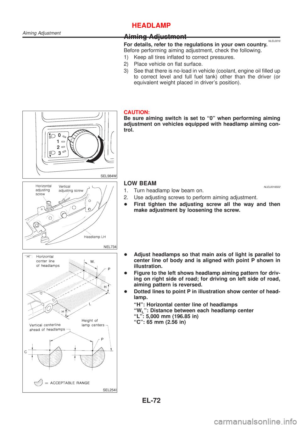
Aiming AdjustmentNLEL0016For details, refer to the regulations in your own country.
Before performing aiming adjustment, check the following.
1) Keep all tires inflated to correct pressures.
2) Place vehicle on flat surface.
3) See that there is no-load in vehicle (coolant, engine oil filled up
to correct level and full fuel tank) other than the driver (or
equivalent weight placed in driver's position).
SEL984W
CAUTION:
Be sure aiming switch is set to ª0º when performing aiming
adjustment on vehicles equipped with headlamp aiming con-
trol.
NEL734
LOW BEAMNLEL0016S021. Turn headlamp low beam on.
2. Use adjusting screws to perform aiming adjustment.
+First tighten the adjusting screw all the way and then
make adjustment by loosening the screw.
SEL254I
+Adjust headlamps so that main axis of light is parallel to
center line of body and is aligned with point P shown in
illustration.
+Figure to the left shows headlamp aiming pattern for driv-
ing on right side of road; for driving on left side of road,
aiming pattern is reversed.
+Dotted lines to point P in illustration show center of head-
lamp.
ªHº: Horizontal center line of headlamps
ªW
Lº: Distance between each headlamp center
ªLº: 5,000 mm (196.85 in)
ªCº: 65 mm (2.56 in)
HEADLAMP
Aiming Adjustment
EL-72
Page 1829 of 3051
NEL714
Aiming Adjustment=NLEL0029Before performing aiming adjustment, make sure of the following.
1) Keep all tires inflated to correct pressure.
2) Place vehicle on level ground.
3) See that vehicle is unloaded (except for full levels of coolant,
engine oil and fuel, and spare tire, jack, and tools). Have the
driver or equivalent weight placed in driver's seat.
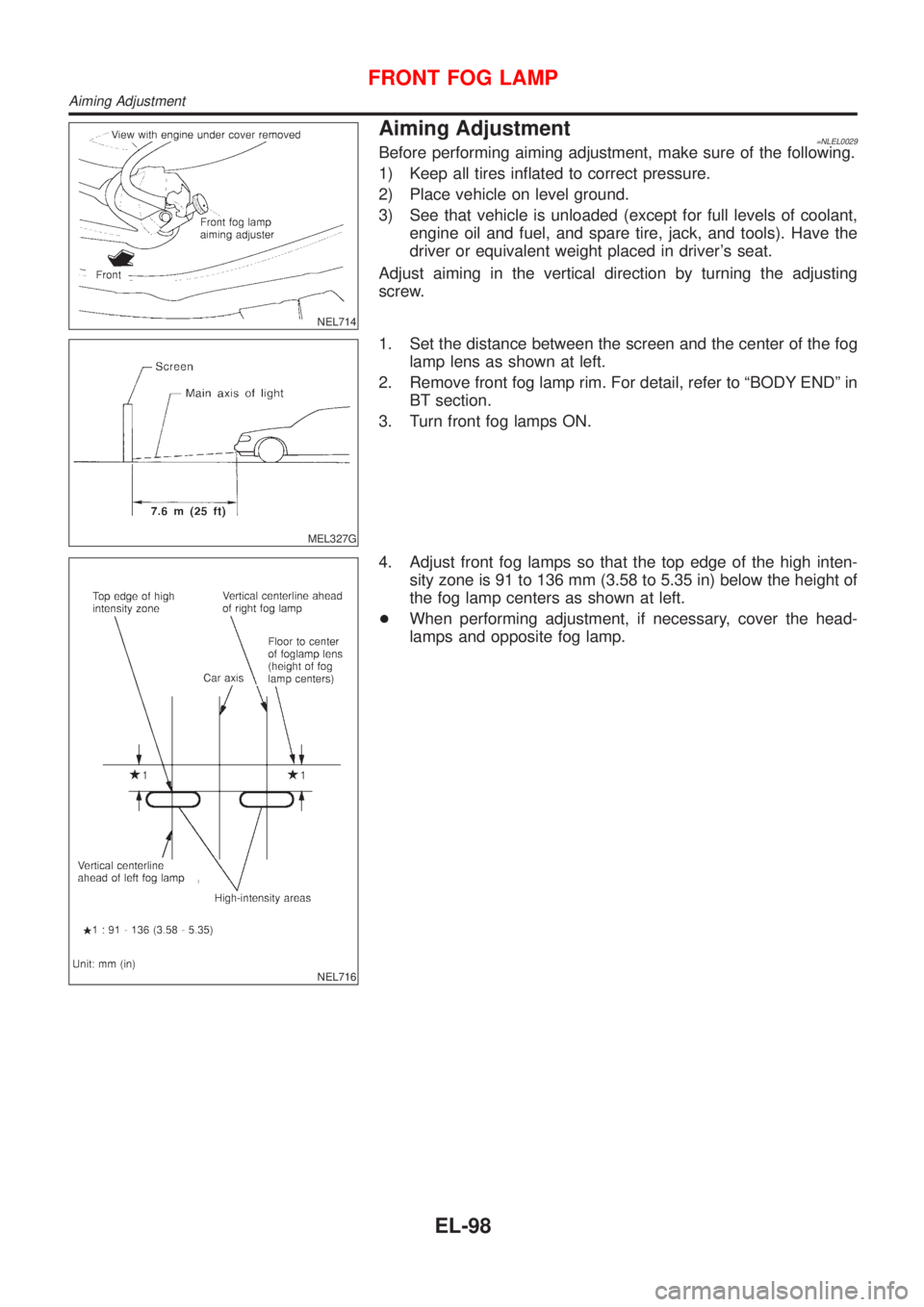
Adjust aiming in the vertical direction by turning the adjusting
screw.
MEL327G
1. Set the distance between the screen and the center of the fog
lamp lens as shown at left.
2. Remove front fog lamp rim. For detail, refer to ªBODY ENDº in
BT section.
3. Turn front fog lamps ON.
NEL716
4. Adjust front fog lamps so that the top edge of the high inten-
sity zone is 91 to 136 mm (3.58 to 5.35 in) below the height of
the fog lamp centers as shown at left.
+When performing adjustment, if necessary, cover the head-
lamps and opposite fog lamp.
FRONT FOG LAMP
Aiming Adjustment
EL-98
Page 1862 of 3051
![NISSAN ALMERA TINO 2001 Service Repair Manual POWER SUPPLY AND GROUND CIRCUITNLEL0442S03Power is supplied at all times
+through 10A fuse [No. 12, located in the fuse block (J/B)]
+to combination meter terminal 8.
With the ignition switch in the O](/manual-img/5/57352/w960_57352-1861.png "NISSAN ALMERA TINO 2001 Service Repair Manual POWER SUPPLY AND GROUND CIRCUITNLEL0442S03Power is supplied at all times
+through 10A fuse [No. 12, located in the fuse block (J/B)]
+to combination meter terminal 8.
With the ignition switch in the O")
POWER SUPPLY AND GROUND CIRCUITNLEL0442S03Power is supplied at all times
+through 10A fuse [No. 12, located in the fuse block (J/B)]
+to combination meter terminal 8.
With the ignition switch in the ON or START position, power is supplied
+through 10A fuse [No. 30, located in the fuse block (J/B)]
+to combination meter terminal 9.
Ground is supplied
+through body grounds M28 and M48
+to combination meter terminal 7.
WATER TEMPERATURE GAUGENLEL0442S04The water temperature gauge indicates the engine coolant temperature. The reading on the gauge is based
on the resistance of the thermal transmitter.
As the temperature of the coolant increases, the resistance of the thermal transmitter decreases. A variable
ground is supplied to terminal 5 of the combination meter for the water temperature gauge. The needle on the
gauge moves from ªCº to ªHº.
TACHOMETERNLEL0442S05The tachometer indicates engine speed in revolutions per minute (rpm).
The tachometer is regulated by a signal
+from terminal 32 (Gasoline engine models) or 439 (Diesel engine models) of the ECM
+to combination meter terminal 19 for the tachometer.
FUEL GAUGENLEL0442S06The fuel gauge indicates the approximate fuel level in the fuel tank.
The fuel gauge is regulated by a variable ground signal supplied
+from body grounds M28 and M48
+through terminals 4 and 7 of combination meter,
+through terminal 1 of the fuel level sensor unit and
+through terminal 4 of the fuel level sensor unit
+to combination meter terminal 3 for the fuel gauge.
SPEEDOMETERNLEL0442S07The combination meter provides a voltage signal to the vehicle speed sensor for the speedometer.
The voltage is supplied
+from combination meter terminal 18 for the speedometer
+to terminal 1 of the vehicle speed sensor.
Ground is supplied
+from body grounds M28 and M48
+through terminals 6 and 7 of combination meter
+to terminal 2 of the vehicle speed sensor.
The speedometer converts the voltage into the vehicle speed displayed.
METERS AND GAUGES
System Description (Cont'd)
EL-131
Page 2476 of 3051
crankshaft position sensor (TDC sensor) from the assem-
bly.
+Always pay extra attention not to damage edge of crank-
shaft position sensor (TDC sensor) or ring gear teeth.
REMOVALNLEM0069S011. Remove engine undercover, and hood for hoisting.
2. Drain coolant from both cylinder block and radiator. Refer to
LC-59, ªChanging Engine Coolantº.
3. Remove the following parts:
+Battery
+RH and LH front wheels
+RH and LH splash covers (combined with undercover)
+Auxiliary belts
+Alternator
+Alternator brackets
+Radiator and cooling fan
+Engine cover
+Air ducts and air cleaner case
LH side of engine room:
4. Disconnect all harnesses and grounds that are connected to
components on vehicle.
5. Disconnect vacuum hose on vacuum pump side.
6. Disconnect fuel feed and fuel return hoses on engine side.
+Immediately put blind plugs into the openings to prevent
fuel from flowing out.
7. Disconnect heater hose. Plug opening of hose to prevent cool-
ant from flowing out.
RH side of engine room:
8. Remove air conditioner compressor from brackets and move
it toward vehicle side. Secure compressor on vehicle side with
rope.
Vehicle underside:
9. Remove exhaust front tube.
10. Disconnect two hoses from power steering pump and plug to
stop fluid.
11. Remove M/T control rod and support rod.
12. Remove ABS wheel sensor, and temporarily hang brake cali-
per with rope on vehicle side.
13. Remove RH and LH drive shafts.
SEM499G
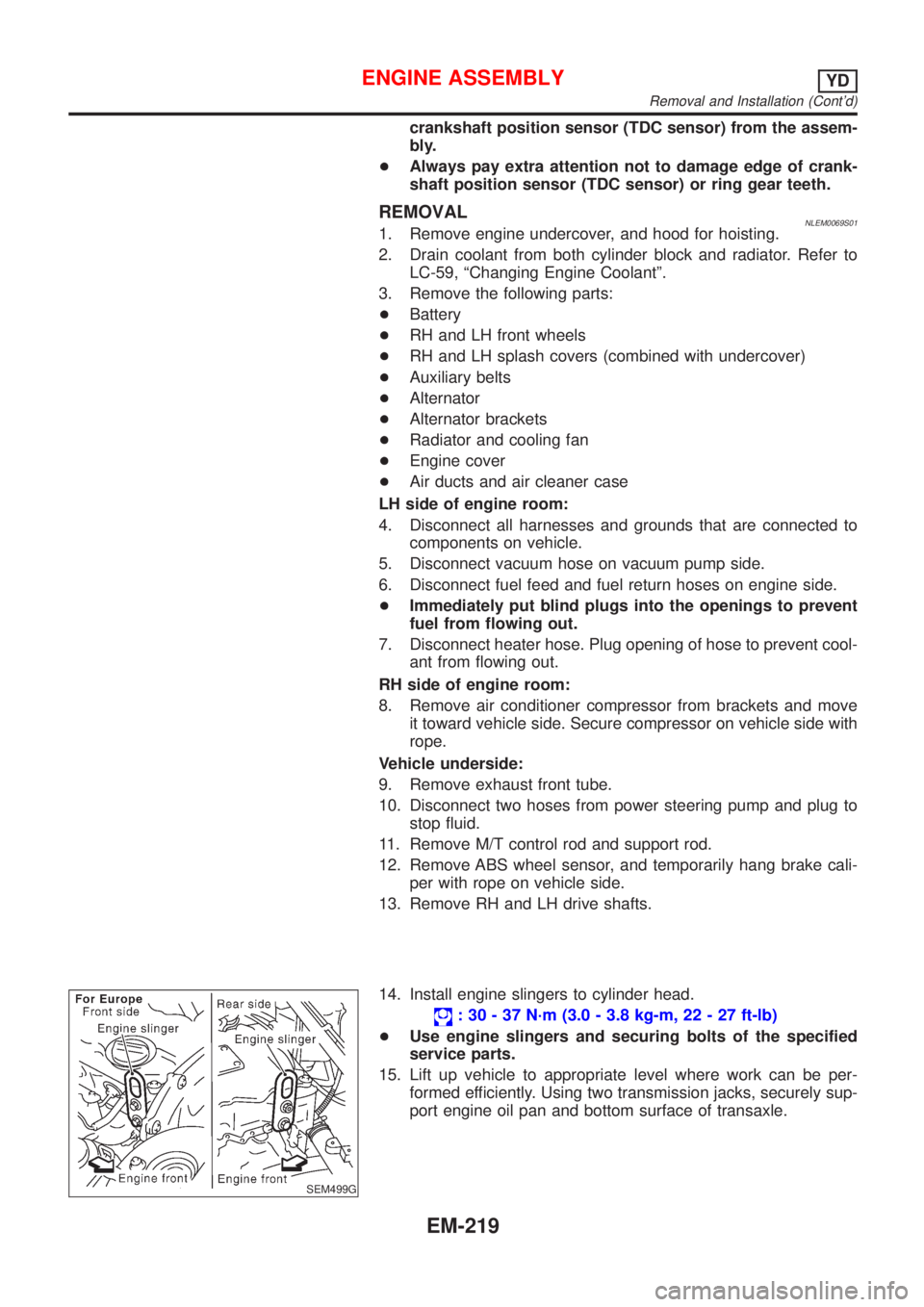
14. Install engine slingers to cylinder head.
: 30 - 37 N´m (3.0 - 3.8 kg-m, 22 - 27 ft-lb)
+Use engine slingers and securing bolts of the specified
service parts.
15. Lift up vehicle to appropriate level where work can be per-
formed efficiently. Using two transmission jacks, securely sup-
port engine oil pan and bottom surface of transaxle.
ENGINE ASSEMBLYYD
Removal and Installation (Cont'd)
EM-219
Page 2723 of 3051
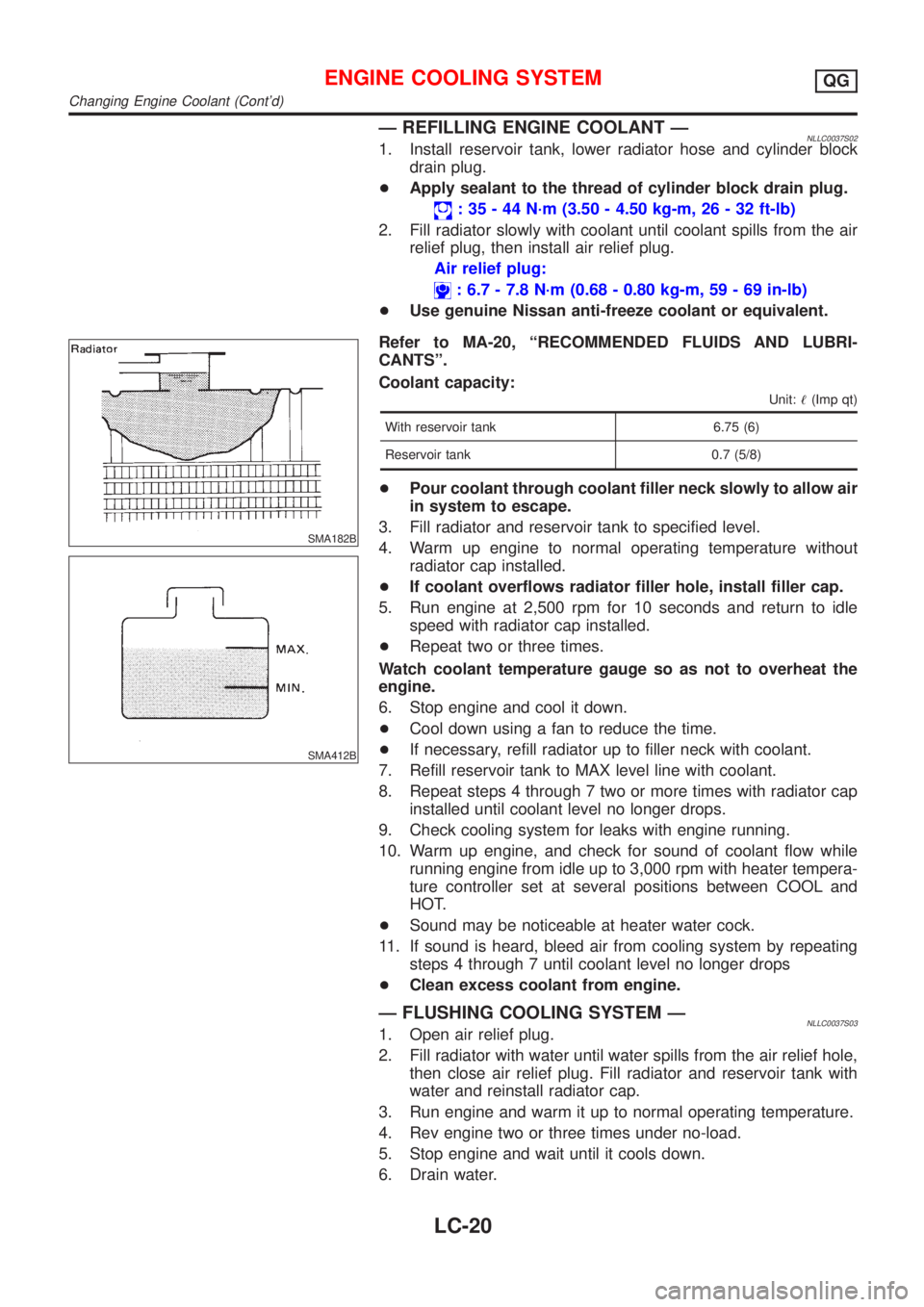
Ð REFILLING ENGINE COOLANT ÐNLLC0037S021. Install reservoir tank, lower radiator hose and cylinder block
drain plug.
+Apply sealant to the thread of cylinder block drain plug.
: 35 - 44 N´m (3.50 - 4.50 kg-m, 26 - 32 ft-lb)
2. Fill radiator slowly with coolant until coolant spills from the air
relief plug, then install air relief plug.
Air relief plug:
: 6.7 - 7.8 N´m (0.68 - 0.80 kg-m, 59 - 69 in-lb)
+Use genuine Nissan anti-freeze coolant or equivalent.
SMA182B
SMA412B
Refer to MA-20, ªRECOMMENDED FLUIDS AND LUBRI-
CANTSº.
Coolant capacity:
Unit:!(Imp qt)
With reservoir tank 6.75 (6)
Reservoir tank 0.7 (5/8)
+Pour coolant through coolant filler neck slowly to allow air
in system to escape.
3. Fill radiator and reservoir tank to specified level.
4. Warm up engine to normal operating temperature without
radiator cap installed.
+If coolant overflows radiator filler hole, install filler cap.
5. Run engine at 2,500 rpm for 10 seconds and return to idle
speed with radiator cap installed.
+Repeat two or three times.
Watch coolant temperature gauge so as not to overheat the
engine.
6. Stop engine and cool it down.
+Cool down using a fan to reduce the time.
+If necessary, refill radiator up to filler neck with coolant.
7. Refill reservoir tank to MAX level line with coolant.
8. Repeat steps 4 through 7 two or more times with radiator cap
installed until coolant level no longer drops.
9. Check cooling system for leaks with engine running.
10. Warm up engine, and check for sound of coolant flow while
running engine from idle up to 3,000 rpm with heater tempera-
ture controller set at several positions between COOL and
HOT.
+Sound may be noticeable at heater water cock.
11. If sound is heard, bleed air from cooling system by repeating
steps 4 through 7 until coolant level no longer drops
+Clean excess coolant from engine.
Ð FLUSHING COOLING SYSTEM ÐNLLC0037S031. Open air relief plug.
2. Fill radiator with water until water spills from the air relief hole,
then close air relief plug. Fill radiator and reservoir tank with
water and reinstall radiator cap.
3. Run engine and warm it up to normal operating temperature.
4. Rev engine two or three times under no-load.
5. Stop engine and wait until it cools down.
6. Drain water.
ENGINE COOLING SYSTEMQG
Changing Engine Coolant (Cont'd)
LC-20
Page 2742 of 3051
SMA182B
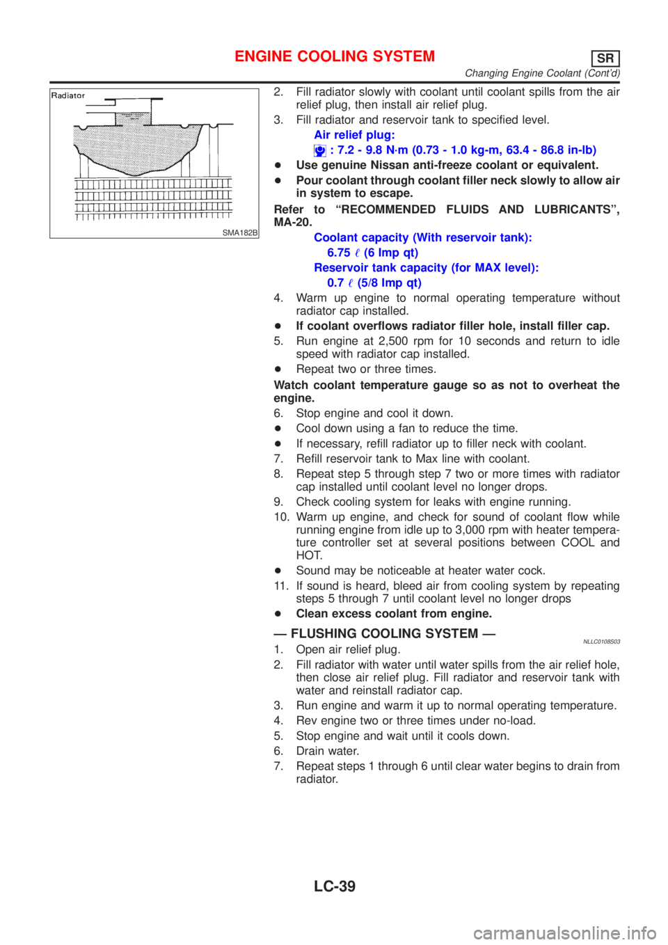
2. Fill radiator slowly with coolant until coolant spills from the air
relief plug, then install air relief plug.
3. Fill radiator and reservoir tank to specified level.
Air relief plug:
: 7.2 - 9.8 N´m (0.73 - 1.0 kg-m, 63.4 - 86.8 in-lb)
+Use genuine Nissan anti-freeze coolant or equivalent.
+Pour coolant through coolant filler neck slowly to allow air
in system to escape.
Refer to ªRECOMMENDED FLUIDS AND LUBRICANTSº,
MA-20.
Coolant capacity (With reservoir tank):
6.75!(6 Imp qt)
Reservoir tank capacity (for MAX level):
0.7!(5/8 Imp qt)
4. Warm up engine to normal operating temperature without
radiator cap installed.
+If coolant overflows radiator filler hole, install filler cap.
5. Run engine at 2,500 rpm for 10 seconds and return to idle
speed with radiator cap installed.
+Repeat two or three times.
Watch coolant temperature gauge so as not to overheat the
engine.
6. Stop engine and cool it down.
+Cool down using a fan to reduce the time.
+If necessary, refill radiator up to filler neck with coolant.
7. Refill reservoir tank to Max line with coolant.
8. Repeat step 5 through step 7 two or more times with radiator
cap installed until coolant level no longer drops.
9. Check cooling system for leaks with engine running.
10. Warm up engine, and check for sound of coolant flow while
running engine from idle up to 3,000 rpm with heater tempera-
ture controller set at several positions between COOL and
HOT.
+Sound may be noticeable at heater water cock.
11. If sound is heard, bleed air from cooling system by repeating
steps 5 through 7 until coolant level no longer drops
+Clean excess coolant from engine.
Ð FLUSHING COOLING SYSTEM ÐNLLC0108S031. Open air relief plug.
2. Fill radiator with water until water spills from the air relief hole,
then close air relief plug. Fill radiator and reservoir tank with
water and reinstall radiator cap.
3. Run engine and warm it up to normal operating temperature.
4. Rev engine two or three times under no-load.
5. Stop engine and wait until it cools down.
6. Drain water.
7. Repeat steps 1 through 6 until clear water begins to drain from
radiator.
ENGINE COOLING SYSTEMSR
Changing Engine Coolant (Cont'd)
LC-39