2001 NISSAN ALMERA TINO CHAIN
[x] Cancel search: CHAINPage 2132 of 3051
Self-diagnosis ModeNLEL0515APPLICATION ITEMSNLEL0515S01
Mode DescriptionReference
page
Self DiagnosisSelf-diagnosis for Navigation, Display and GPS Antenna
connection.EL-402
Confirmation/
adjustmentDiagnose the DisplayColor and gray gradation of display can be checked in
this mode.EL-410
Diagnosis for Signals from the CarSeveral input signals to NAVI control unit, can be moni-
tored in this mode.EL-408
NavigationCheck the map CD-
ROM versionThe version (parts number) of inserted CD-ROM can be
checked in this model.EL-409
Error historyDiagnosis results previously stored in the memory
(before turning ignition switch ON) are displayed in this
mode. Time and location when/where the errors
occurred are also displayed.EL-404
Longitude & LatitudeDisplay the map. Use the joystick to adjust position. Lon-
gitude and latitude will be displayed.EL-411
Adjust the AngleTurning angle of the vehicle on the display can be
adjusted in this mode.EL-412
Speed CalibrationUnder ordinary conditions, the navigation system dis-
tance measuring function will automatically compensate
for minute decreases in wheel and tire diameter caused
by tire wear or low pressure. Speed calibration immedi-
ately restores system accuracy in cases such as when
distance calibration is needed because of the use of tire
chains in inclement weather.EL-413
Initialize LocationThis mode is for initializing the current location. Use
when the vehicle is transported a long distance by a
trailer, etc.EL-414
NEL729
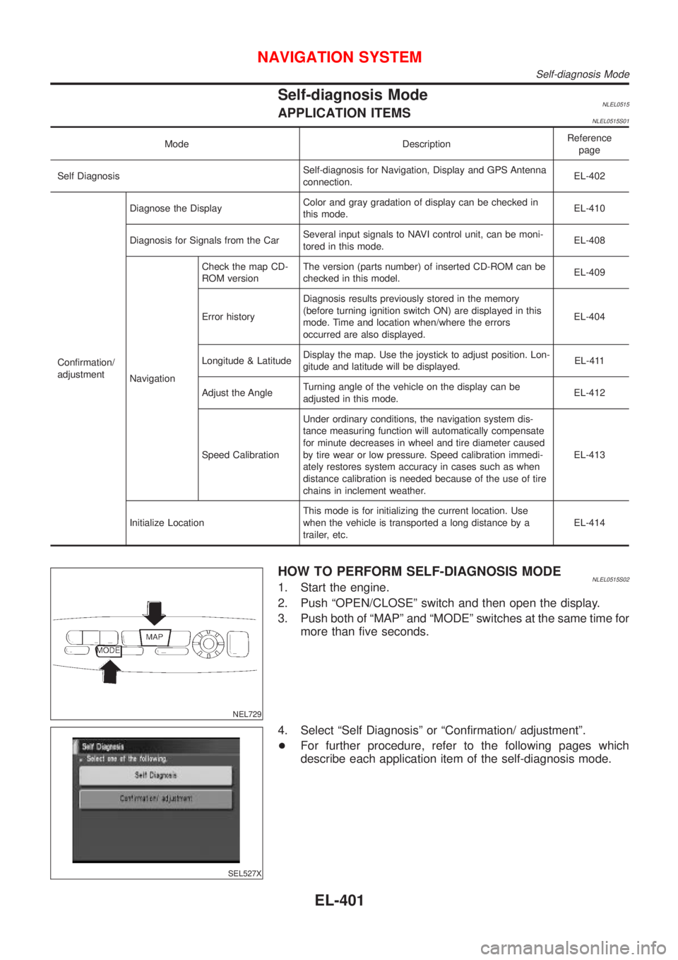
HOW TO PERFORM SELF-DIAGNOSIS MODENLEL0515S021. Start the engine.
2. Push ªOPEN/CLOSEº switch and then open the display.
3. Push both of ªMAPº and ªMODEº switches at the same time for
more than five seconds.
SEL527X
4. Select ªSelf Diagnosisº or ªConfirmation/ adjustmentº.
+For further procedure, refer to the following pages which
describe each application item of the self-diagnosis mode.
NAVIGATION SYSTEM
Self-diagnosis Mode
EL-401
Page 2165 of 3051
Possible cause Drive condition Service procedure
AreaSlippery road surfaceOn wet, icy, or gravel road where
frequent wheel slippage occurs, dis-
tance calculations may be errone-
ous. The position marker may show
the vehicle to be in inaccurate posi-
tion.
If the position marker does
not move to the correct posi-
tion even after the vehicle
has been driven approxi-
mately 10 km (6 miles), per-
form ªAdjust Current Loca-
tionº MODE (EL-421). If
necessary, perform ªSpeed
Calibrationº (EL-413). Slanted areaHilly areas where the road has
banked curves. When the vehicle
enters these banked curves, there
may be an error in steering angle
measurement. The position marker
may show the vehicle to be in inac-
curate position.
Map
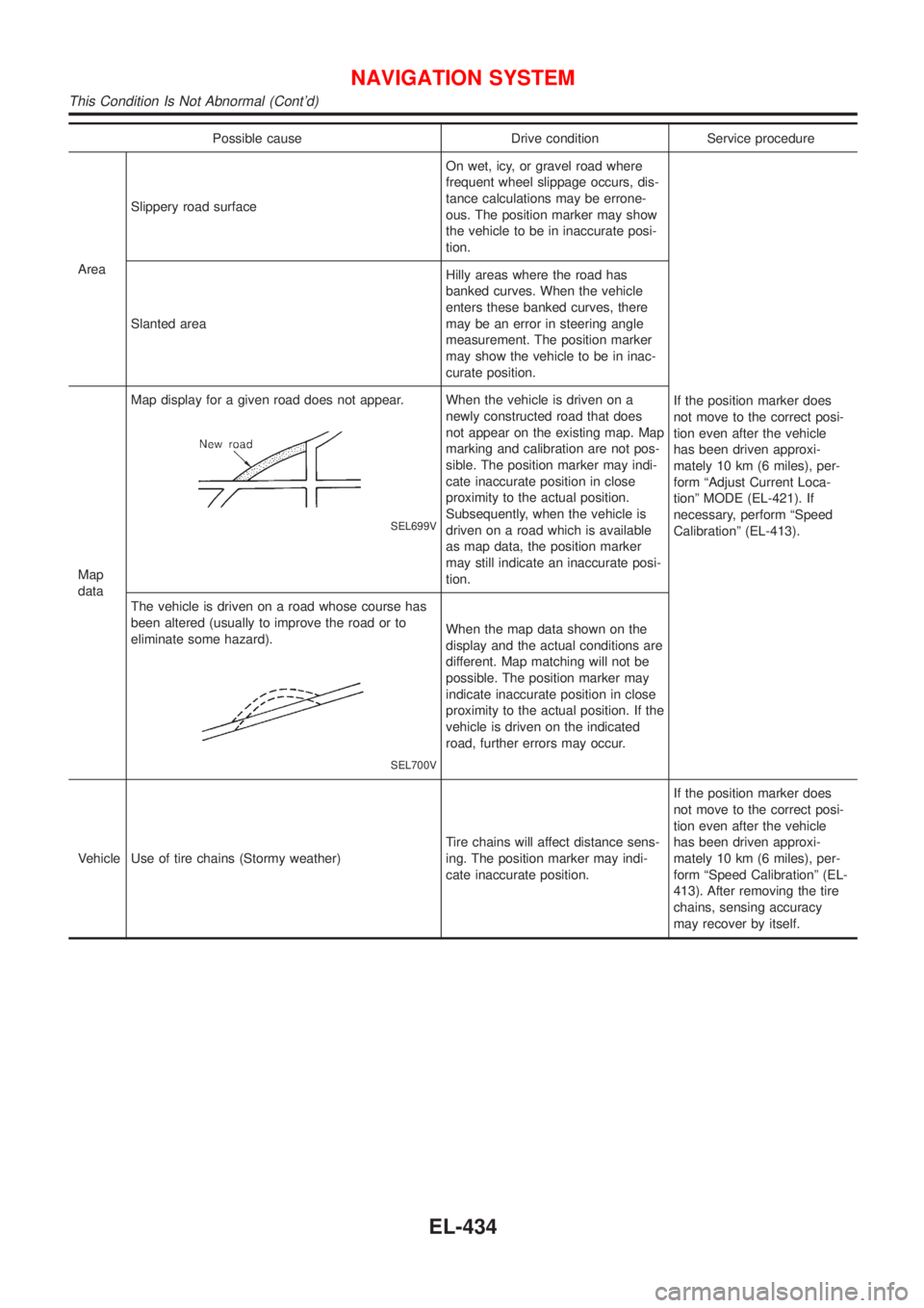
dataMap display for a given road does not appear.
SEL699V
When the vehicle is driven on a
newly constructed road that does
not appear on the existing map. Map
marking and calibration are not pos-
sible. The position marker may indi-
cate inaccurate position in close
proximity to the actual position.
Subsequently, when the vehicle is
driven on a road which is available
as map data, the position marker
may still indicate an inaccurate posi-
tion.
The vehicle is driven on a road whose course has
been altered (usually to improve the road or to
eliminate some hazard).
SEL700V
When the map data shown on the
display and the actual conditions are
different. Map matching will not be
possible. The position marker may
indicate inaccurate position in close
proximity to the actual position. If the
vehicle is driven on the indicated
road, further errors may occur.
Vehicle Use of tire chains (Stormy weather)Tire chains will affect distance sens-
ing. The position marker may indi-
cate inaccurate position.If the position marker does
not move to the correct posi-
tion even after the vehicle
has been driven approxi-
mately 10 km (6 miles), per-
form ªSpeed Calibrationº (EL-
413). After removing the tire
chains, sensing accuracy
may recover by itself.
NAVIGATION SYSTEM
This Condition Is Not Abnormal (Cont'd)
EL-434
Page 2169 of 3051
GPS signal reception conditions are good. However, the position mark does not return to its proper
position.
+The system senses the vehicle location with an error of approximately 100 m (328 ft). Due to the limita-
tion of precision, the position marker may be inaccurate even if the GPS signal reception condition is good.
+The navigation system uses GPS data to determine vehicle location. GPS data is compared with other
locational sensing data during the map matching process. The system decides which data is more pre-
cise and uses that data.
+When the vehicle is stationary, GPS data cannot be used to make system corrections.
Area designations on the map display and the BIRDVIEW
Tdisplay differ.
To prevent the display from becoming congested, alphanumeric information is abridged.
[No problem]
Correct position of your vehicle is not displayed.
Vehicle position changed after ignition key was turned to the OFF position (Vehicle is transported on car ferry,
car train, or by some other means).
[Operate vehicle for short time under GPS receiving conditions.]
The display does not change to night-time mode even though the light switch has been turned ON.
Lights have been turned on. In ªDISPLAY CHANGEº mode, night-time mode on display has been switched to
day-time mode and still is.
[Turn lights on again. Set the display to night-time mode. Refer to EL-419.]
Map does not scroll even though the position of your vehicle is changed.
Present area does not appear on the display.
[Press the ªMAPº switch.]
Vehicle position marker does not appear.
Present area does not appear on the display.
[Press the ªMAPº switch.]
The map surface precision display (GPS satellite marker) still remains gray.
Vehicle is parked inside a building or in the shadow of a large building. This intercepts the GPS signal.
[Move the vehicle to a more open position.]
GPS signal is not received because objects are placed on the rear parcel shelf.
[Remove objects from the rear parcel shelf.]
GPS satellite position is bad.
[Wait until GPS satellite position improves.]
Vehicle position precision is bad.
The map surface precision display (GPS satellite marker) still remains gray.
[Refer to ªThe map surface precision display (GPS satellite marker) still remains grayº item (Symptoms)]
Vehicle speed and elapsed distance is calculated from the vehicle speed pulse. This pulse is dependent upon
tire size. If tire chains are used on the vehicle, accuracy will be affected (pulse rate will be too fast or too slow).
The same is true if the system installed to your vehicle is removed and installed on another vehicle.
[Drive the vehicle at a speed higher than 30 km/h (19 MPH) for approximately 30 minutes. Automatic read-
justment should occur. If it does not (remains too fast or too slow), distance calibration is required. Or, drive
the vehicle for a short distance. Perform ªSPEED CALIBRATIONº (EL-413). After removing the tire chains,
sensing accuracy may recover by itself.]
Bad map data or system defect (same error consistently occurs in the same area)
ROUTE SEARCH/ROUTE GUIDENLEL0522S03+If the present location or the destination location is displayed in the avoid area, it is not possible to search
routes.
+If the avoid area is set to wide range area, it may not be possible to find appropriate routes or search for
alternate routes.
+The automatic re-route calculates a return to the original route. Because of this, it may not be possible to
search appropriate new routes. If you deviate from the original route and wish to select an appropriate new
route, touch ªRoute Calculationº.
+The automatic re-route function may sometimes require considerable time.
+Displayed route number and directional information at a highway junction may differ from the information
posted on the actual road signs.
+Displayed street name information at a highway exit may differ from the information posted on the actual
road signs.
+Street name information displayed on the enlarged intersection map may differ from the information posted
on the actual road signs.
NAVIGATION SYSTEM
This Condition Is Not Abnormal (Cont'd)
EL-438
Page 2258 of 3051
ENGINE MECHANICAL
SECTION
EM
CONTENTS
QG
PRECAUTIONS...............................................................5
Parts Requiring Angular Tightening .............................5
Liquid Gasket Application Procedure ..........................5
PREPARATION...............................................................6
Special Service Tools ..................................................6
Commercial Service Tools ...........................................8
NOISE, VIBRATION AND HARSHNESS (NVH)
TROUBLESHOOTING...................................................10
NVH Troubleshooting - Engine Noise .......................10
OUTER COMPONENT PARTS.....................................12
Removal and Installation ...........................................12
MEASUREMENT OF COMPRESSION PRESSURE....16
DRIVE BELTS................................................................17
Checking ....................................................................17
AIR CLEANER...............................................................18
Changing Air Cleaner Filter .......................................18
VISCOUS PAPER TYPE...........................................18
SPARK PLUG................................................................19
Checking and Changing ............................................19
OIL PAN.........................................................................20
Components...............................................................20
Removal .....................................................................20
Installation ..................................................................21
TIMING CHAIN..............................................................22
Components...............................................................22
Removal .....................................................................23
Inspection...................................................................26
Installation ..................................................................27
OIL SEAL.......................................................................31
Replacement ..............................................................31
VALVE OIL SEAL.....................................................31
FRONT OIL SEAL....................................................31
REAR OIL SEAL......................................................32
CYLINDER HEAD..........................................................33
Components...............................................................33
Removal .....................................................................34
Disassembly...............................................................36Inspection...................................................................36
CYLINDER HEAD DISTORTION...............................36
CAMSHAFT VISUAL CHECK....................................36
CAMSHAFT RUNOUT..............................................37
CAMSHAFT CAM HEIGHT.......................................37
CAMSHAFT JOURNAL CLEARANCE........................37
CAMSHAFT END PLAY............................................38
CAMSHAFT SPROCKET RUNOUT...........................38
VALVE GUIDE CLEARANCE....................................38
VALVE GUIDE REPLACEMENT................................39
VALVE SEATS.........................................................40
REPLACING VALVE SEAT FOR SERVICE PARTS....40
VALVE DIMENSIONS...............................................41
VALVE SPRING.......................................................41
VALVE LIFTER AND VALVE SHIM............................41
Valve Clearance.........................................................42
CHECKING.............................................................42
ADJUSTING............................................................43
Assembly ...................................................................45
Installation ..................................................................45
ENGINE ASSEMBLY.....................................................49
Removal and Installation ...........................................49
REMOVAL...............................................................50
INSTALLATION........................................................51
CYLINDER BLOCK.......................................................52
Components...............................................................52
Removal and Installation ...........................................53
Disassembly...............................................................53
PISTON AND CRANKSHAFT....................................53
Inspection...................................................................54
PISTON AND PISTON PIN CLEARANCE..................54
PISTON RING SIDE CLEARANCE............................54
PISTON RING END GAP..........................................54
CONNECTING ROD BEND AND TORSION...............55
CYLINDER BLOCK DISTORTION AND WEAR...........55
PISTON-TO-BORE CLEARANCE..............................56
CRANKSHAFT.........................................................57
BEARING CLEARANCE...........................................57
CONNECTING ROD BUSHING CLEARANCE
(SMALL END)
..........................................................59
Page 2259 of 3051
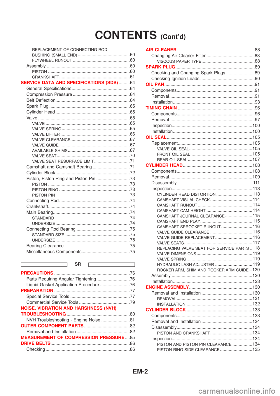
REPLACEMENT OF CONNECTING ROD
BUSHING (SMALL END)
..........................................60
FLYWHEEL RUNOUT..............................................60
Assembly ...................................................................60
PISTON..................................................................60
CRANKSHAFT.........................................................61
SERVICE DATA AND SPECIFICATIONS (SDS).........64
General Specifications ...............................................64
Compression Pressure ..............................................64
Belt Deflection............................................................64
Spark Plug .................................................................65
Cylinder Head ............................................................65
Valve ..........................................................................65
VALVE....................................................................65
VALVE SPRING.......................................................65
VALVE LIFTER........................................................66
VALVE CLEARANCE................................................67
VALVE GUIDE.........................................................67
AVAILABLE SHIMS..................................................67
VALVE SEAT...........................................................70
VALVE SEAT RESURFACE LIMIT.............................71
Camshaft and Camshaft Bearing ..............................71
Cylinder Block ............................................................72
Piston, Piston Ring and Piston Pin ...........................73
PISTON..................................................................73
PISTON RING.........................................................73
PISTON PIN............................................................73
Connecting Rod .........................................................74
Crankshaft..................................................................74
Main Bearing..............................................................74
STANDARD.............................................................74
UNDERSIZE............................................................74
Connecting Rod Bearing ...........................................75
STANDARD SIZE....................................................75
UNDERSIZE............................................................75
Bearing Clearance .....................................................75
Miscellaneous Components.......................................75
SR
PRECAUTIONS.............................................................76
Parts Requiring Angular Tightening ...........................76
Liquid Gasket Application Procedure ........................76
PREPARATION.............................................................77
Special Service Tools ................................................77
Commercial Service Tools .........................................79
NOISE, VIBRATION AND HARSHNESS (NVH)
TROUBLESHOOTING...................................................80
NVH Troubleshooting - Engine Noise .......................81
OUTER COMPONENT PARTS.....................................82
Removal and Installation ...........................................82
MEASUREMENT OF COMPRESSION PRESSURE....85
DRIVE BELTS................................................................86
Checking ....................................................................86AIR CLEANER...............................................................88
Changing Air Cleaner Filter .......................................88
VISCOUS PAPER TYPE...........................................88
SPARK PLUG................................................................89
Checking and Changing Spark Plugs .......................89
Checking Ignition Leads ............................................90
OIL PAN.........................................................................91
Components...............................................................91
Removal .....................................................................91
Installation ..................................................................93
TIMING CHAIN..............................................................96
Components...............................................................96
Removal .....................................................................97
Inspection.................................................................100
Installation ................................................................100
OIL SEAL.....................................................................105
Replacement ............................................................105
VALVE OIL SEAL...................................................105
FRONT OIL SEAL..................................................105
REAR OIL SEAL....................................................107
CYLINDER HEAD........................................................108
Components.............................................................108
Removal ...................................................................109
Disassembly............................................................. 111
Inspection................................................................. 113
CYLINDER HEAD DISTORTION............................. 113
CAMSHAFT VISUAL CHECK.................................. 114
CAMSHAFT RUNOUT............................................ 114
CAMSHAFT CAM HEIGHT..................................... 114
CAMSHAFT JOURNAL CLEARANCE...................... 115
CAMSHAFT END PLAY.......................................... 115
CAMSHAFT SPROCKET RUNOUT......................... 116
VALVE GUIDE CLEARANCE.................................. 116
VALVE GUIDE REPLACEMENT.............................. 116
VALVE SEATS....................................................... 117
REPLACING VALVE SEAT FOR SERVICE PARTS.. 118
VALVE DIMENSIONS............................................. 119
VALVE SPRING..................................................... 119
HYDRAULIC LASH ADJUSTER.............................. 119
ROCKER ARM, SHIM AND ROCKER ARM GUIDE...120
Assembly .................................................................120
Installation ................................................................123
ENGINE ASSEMBLY...................................................130
Removal and Installation .........................................130
REMOVAL.............................................................131
INSTALLATION......................................................132
CYLINDER BLOCK.....................................................133
Components.............................................................133
Removal and Installation .........................................134
Disassembly.............................................................134
PISTON AND CRANKSHAFT..................................134
Inspection.................................................................134
PISTON AND PISTON PIN CLEARANCE................134
PISTON RING SIDE CLEARANCE..........................135
CONTENTS(Cont'd)
EM-2
Page 2260 of 3051
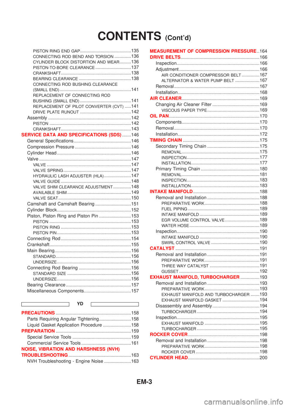
PISTON RING END GAP........................................135
CONNECTING ROD BEND AND TORSION.............136
CYLINDER BLOCK DISTORTION AND WEAR.........136
PISTON-TO-BORE CLEARANCE............................137
CRANKSHAFT.......................................................138
BEARING CLEARANCE.........................................138
CONNECTING ROD BUSHING CLEARANCE
(SMALL END)
........................................................141
REPLACEMENT OF CONNECTING ROD
BUSHING (SMALL END)
........................................141
REPLACEMENT OF PILOT CONVERTER (CVT).....141
DRIVE PLATE RUNOUT........................................142
Assembly .................................................................142
PISTON................................................................142
CRANKSHAFT.......................................................143
SERVICE DATA AND SPECIFICATIONS (SDS).......146
General Specifications .............................................146
Compression Pressure ............................................146
Cylinder Head ..........................................................146
Valve ........................................................................147
VALVE..................................................................147
VALVE SPRING.....................................................147
HYDRAULIC LASH ADJUSTER (HLA).....................147
VALVE GUIDE.......................................................148
VALVE SHIM CLEARANCE ADJUSTMENT..............148
AVAILABLE SHIM..................................................149
VALVE SEAT.........................................................150
Camshaft and Camshaft Bearing ............................151
Cylinder Block ..........................................................152
Piston, Piston Ring and Piston Pin .........................153
PISTON................................................................153
PISTON RING.......................................................153
PISTON PIN..........................................................153
Connecting Rod .......................................................154
Crankshaft................................................................155
Main Bearing............................................................156
STANDARD...........................................................156
UNDERSIZE..........................................................156
Connecting Rod Bearing .........................................156
STANDARD SIZE..................................................156
UNDERSIZE..........................................................156
Bearing Clearance ...................................................157
Miscellaneous Components.....................................157
YD
PRECAUTIONS...........................................................158
Parts Requiring Angular Tightening .........................158
Liquid Gasket Application Procedure ......................158
PREPARATION...........................................................159
Special Service Tools ..............................................159
Commercial Service Tools .......................................161
NOISE, VIBRATION AND HARSHNESS (NVH)
TROUBLESHOOTING.................................................163
NVH Troubleshooting - Engine Noise .....................163MEASUREMENT OF COMPRESSION PRESSURE..164
DRIVE BELTS..............................................................166
Inspection.................................................................166
Adjustment ...............................................................166
AIR CONDITIONER COMPRESSOR BELT..............167
ALTERNATOR & WATER PUMP BELT...................167
Removal ...................................................................167
Installation ................................................................168
AIR CLEANER.............................................................169
Changing Air Cleaner Filter .....................................169
VISCOUS PAPER TYPE.........................................169
OIL PAN.......................................................................170
Components.............................................................170
Removal ...................................................................170
Installation ................................................................172
TIMING CHAIN............................................................175
Secondary Timing Chain .........................................175
REMOVAL.............................................................175
INSPECTION.........................................................177
INSTALLATION......................................................177
Primary Timing Chain ..............................................180
REMOVAL.............................................................181
INSPECTION.........................................................183
INSTALLATION......................................................183
INTAKE MANIFOLD....................................................188
Removal and Installation .........................................188
PREPARATIVE WORK...........................................188
FUEL PIPING........................................................189
INTAKE MANIFOLD...............................................189
EGR VOLUME CONTROL VALVE...........................189
WATER HOSE.......................................................189
Inspection.................................................................190
INTAKE MANIFOLD...............................................190
SWIRL CONTROL VALVE......................................190
CATALYST..................................................................191
Removal and Installation .........................................191
PREPARATIVE WORK...........................................191
THREE WAY CATALYST.......................................191
GUSSET...............................................................192
EXHAUST MANIFOLD, TURBOCHARGER...............193
Removal and Installation .........................................193
PREPARATIVE WORK...........................................193
EXHAUST MANIFOLD AND TURBOCHARGER.......193
EXHAUST MANIFOLD GASKET.............................194
Disassembly and Assembly .....................................194
TURBOCHARGER.................................................194
Inspection.................................................................195
EXHAUST MANIFOLD...........................................195
TURBOCHARGER.................................................195
ROCKER COVER........................................................198
Removal and Installation .........................................198
PREPARATIVE WORK...........................................198
ROCKER COVER..................................................198
CYLINDER HEAD........................................................200
CONTENTS(Cont'd)
EM-3
Page 2261 of 3051
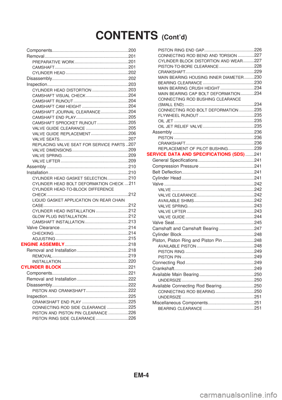
Components.............................................................200
Removal ...................................................................201
PREPARATIVE WORK...........................................201
CAMSHAFT...........................................................201
CYLINDER HEAD..................................................202
Disassembly.............................................................202
Inspection.................................................................203
CYLINDER HEAD DISTORTION.............................203
CAMSHAFT VISUAL CHECK..................................204
CAMSHAFT RUNOUT............................................204
CAMSHAFT CAM HEIGHT.....................................204
CAMSHAFT JOURNAL CLEARANCE......................204
CAMSHAFT END PLAY..........................................205
CAMSHAFT SPROCKET RUNOUT.........................205
VALVE GUIDE CLEARANCE..................................205
VALVE GUIDE REPLACEMENT..............................206
VALVE SEATS.......................................................207
REPLACING VALVE SEAT FOR SERVICE PARTS..207
VALVE DIMENSIONS.............................................209
VALVE SPRING.....................................................209
VALVE LIFTER......................................................209
Assembly .................................................................210
Installation ................................................................210
CYLINDER HEAD GASKET SELECTION.................210
CYLINDER HEAD BOLT DEFORMATION CHECK... 211
CYLINDER HEAD-TO-BLOCK DIFFERENCE
CHECK
.................................................................212
LIQUID GASKET APPLICATION ON REAR CHAIN
CASE
....................................................................212
CYLINDER HEAD INSTALLATION..........................212
GLOW PLUG INSTALLATION.................................212
CAMSHAFT INSTALLATION...................................213
Valve Clearance.......................................................214
CHECKING...........................................................214
ADJUSTING..........................................................215
ENGINE ASSEMBLY...................................................218
Removal and Installation .........................................218
REMOVAL.............................................................219
INSTALLATION......................................................220
CYLINDER BLOCK.....................................................221
Components.............................................................221
Removal and Installation .........................................222
Disassembly.............................................................222
PISTON AND CRANKSHAFT..................................222
Inspection.................................................................225
CRANKSHAFT END PLAY.....................................225
CONNECTING ROD SIDE CLEARANCE.................225
PISTON AND PISTON PIN CLEARANCE................226
PISTON RING SIDE CLEARANCE..........................226
PISTON RING END GAP........................................226
CONNECTING ROD BEND AND TORSION.............227
CYLINDER BLOCK DISTORTION AND WEAR.........227
PISTON-TO-BORE CLEARANCE............................228
CRANKSHAFT.......................................................229
MAIN BEARING HOUSING INNER DIAMETER........230
BEARING CLEARANCE.........................................230
MAIN BEARING CRUSH HEIGHT...........................234
MAIN BEARING CAP BOLT DEFORMATION...........234
CONNECTING ROD BUSHING CLEARANCE
(SMALL END)
........................................................234
CONNECTING ROD BOLT DEFORMATION............235
FLYWHEEL RUNOUT............................................235
OIL JET................................................................235
OIL JET RELIEF VALVE.........................................235
Assembly .................................................................236
PISTON................................................................236
CRANKSHAFT.......................................................236
REPLACEMENT OF PILOT BUSHING.....................239
SERVICE DATA AND SPECIFICATIONS (SDS).......241
General Specifications .............................................241
Compression Pressure ............................................241
Belt Deflection..........................................................241
Cylinder Head ..........................................................241
Valve ........................................................................242
VALVE..................................................................242
VALVE CLEARANCE..............................................242
AVAILABLE SHIMS................................................242
VALVE SPRING.....................................................243
VALVE LIFTER......................................................243
VALVE GUIDE.......................................................244
Valve Seat................................................................245
Camshaft and Camshaft Bearing ............................247
Cylinder Block ..........................................................248
Piston, Piston Ring and Piston Pin .........................248
AVAILABLE PISTON..............................................248
PISTON RING.......................................................249
PISTON PIN..........................................................249
Connecting Rod .......................................................249
Crankshaft................................................................249
Available Main Bearing ............................................250
UNDERSIZE..........................................................250
Available Connecting Rod Bearing..........................250
CONNECTING ROD BEARING...............................250
UNDERSIZE..........................................................251
Miscellaneous Components.....................................251
BEARING CLEARANCE.........................................251
CONTENTS(Cont'd)
EM-4
Page 2267 of 3051
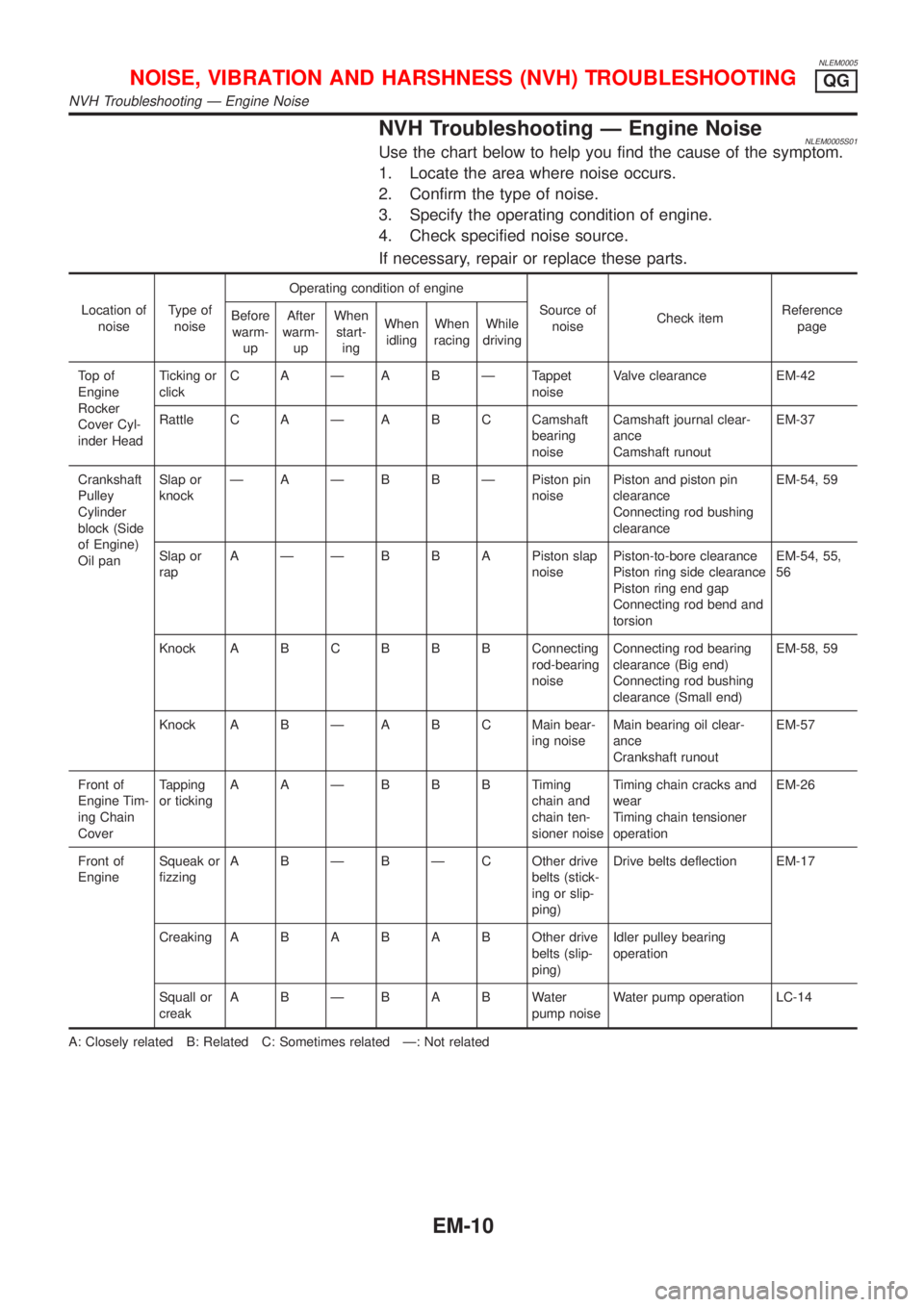
NLEM0005
NVH Troubleshooting Ð Engine NoiseNLEM0005S01Use the chart below to help you find the cause of the symptom.
1. Locate the area where noise occurs.
2. Confirm the type of noise.
3. Specify the operating condition of engine.
4. Check specified noise source.
If necessary, repair or replace these parts.
Location of
noiseType of
noiseOperating condition of engine
Source of
noiseCheck itemReference
page Before
warm-
upAfter
warm-
upWhen
start-
ingWhen
idlingWhen
racingWhile
driving
To p o f
Engine
Rocker
Cover Cyl-
inder HeadTicking or
clickC A Ð A B Ð Tappet
noiseValve clearance EM-42
Rattle C A Ð A B C Camshaft
bearing
noiseCamshaft journal clear-
ance
Camshaft runoutEM-37
Crankshaft
Pulley
Cylinder
block (Side
of Engine)
Oil panSlap or
knockÐ A Ð B B Ð Piston pin
noisePiston and piston pin
clearance
Connecting rod bushing
clearanceEM-54, 59
Slap or
rapA Ð Ð B B A Piston slap
noisePiston-to-bore clearance
Piston ring side clearance
Piston ring end gap
Connecting rod bend and
torsionEM-54, 55,
56
Knock A B CB B B Connecting
rod-bearing
noiseConnecting rod bearing
clearance (Big end)
Connecting rod bushing
clearance (Small end)EM-58, 59
Knock A B Ð A B C Main bear-
ing noiseMain bearing oil clear-
ance
Crankshaft runoutEM-57
Front of
Engine Tim-
ing Chain
CoverTapping
or tickingAAÐBBBTiming
chain and
chain ten-
sioner noiseTiming chain cracks and
wear
Timing chain tensioner
operationEM-26
Front of
EngineSqueak or
fizzingA B Ð B Ð C Other drive
belts (stick-
ing or slip-
ping)Drive belts deflection EM-17
CreakingABABABOther drive
belts (slip-
ping)Idler pulley bearing
operation
Squall or
creakABÐBABWater
pump noiseWater pump operation LC-14
A: Closely related B: Related C: Sometimes related Ð: Not related
NOISE, VIBRATION AND HARSHNESS (NVH) TROUBLESHOOTINGQG
NVH Troubleshooting Ð Engine Noise
EM-10