Page 1961 of 3051
Trouble DiagnosesNLEL0385AUDIO UNITNLEL0385S05
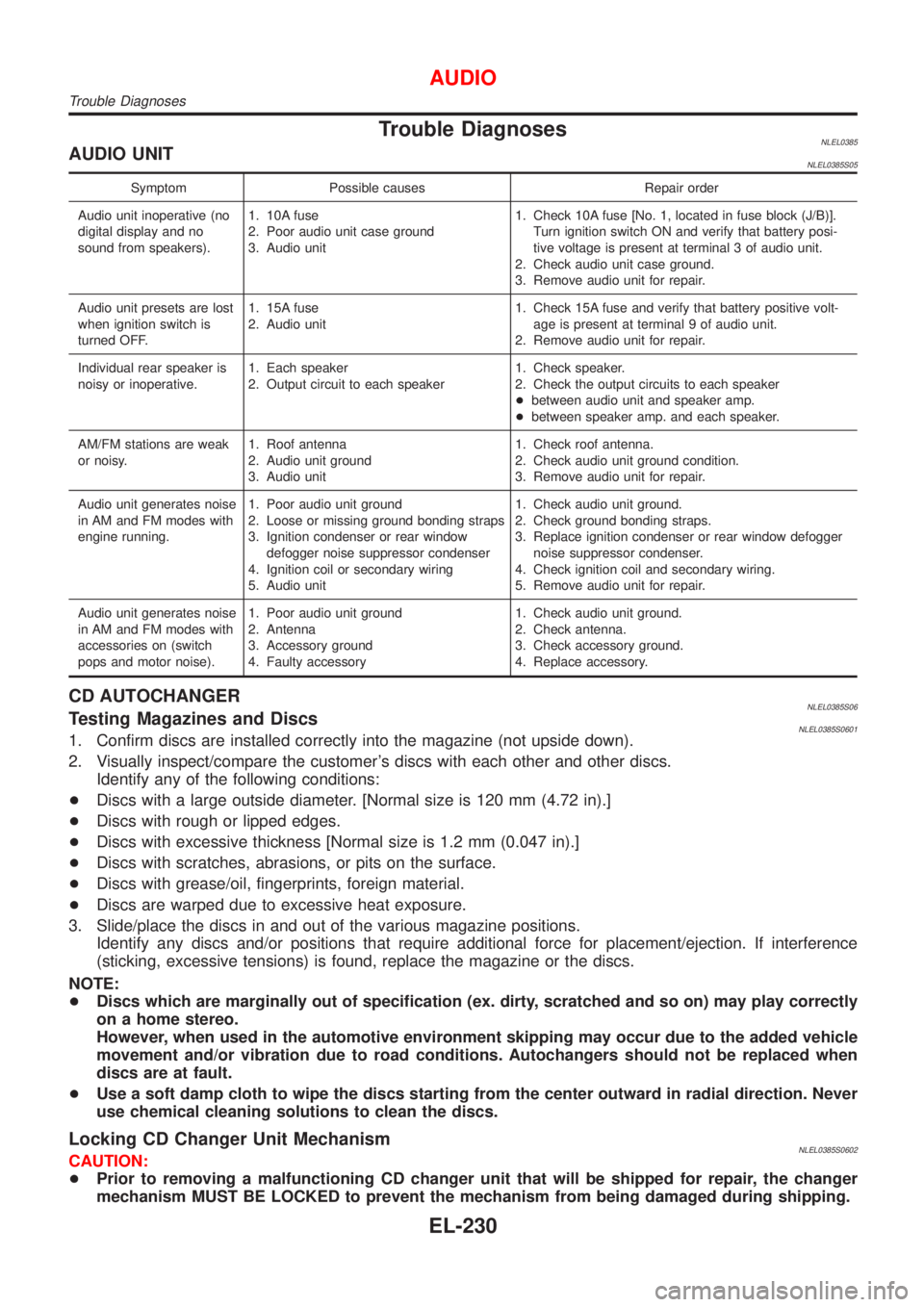
Symptom Possible causes Repair order
Audio unit inoperative (no
digital display and no
sound from speakers).1. 10A fuse
2. Poor audio unit case ground
3. Audio unit1. Check 10A fuse [No. 1, located in fuse block (J/B)].
Turn ignition switch ON and verify that battery posi-
tive voltage is present at terminal 3 of audio unit.
2. Check audio unit case ground.
3. Remove audio unit for repair.
Audio unit presets are lost
when ignition switch is
turned OFF.1. 15A fuse
2. Audio unit1. Check 15A fuse and verify that battery positive volt-
age is present at terminal 9 of audio unit.
2. Remove audio unit for repair.
Individual rear speaker is
noisy or inoperative.1. Each speaker
2. Output circuit to each speaker1. Check speaker.
2. Check the output circuits to each speaker
+between audio unit and speaker amp.
+between speaker amp. and each speaker.
AM/FM stations are weak
or noisy.1. Roof antenna
2. Audio unit ground
3. Audio unit1. Check roof antenna.
2. Check audio unit ground condition.
3. Remove audio unit for repair.
Audio unit generates noise
in AM and FM modes with
engine running.1. Poor audio unit ground
2. Loose or missing ground bonding straps
3. Ignition condenser or rear window
defogger noise suppressor condenser
4. Ignition coil or secondary wiring
5. Audio unit1. Check audio unit ground.
2. Check ground bonding straps.
3. Replace ignition condenser or rear window defogger
noise suppressor condenser.
4. Check ignition coil and secondary wiring.
5. Remove audio unit for repair.
Audio unit generates noise
in AM and FM modes with
accessories on (switch
pops and motor noise).1. Poor audio unit ground
2. Antenna
3. Accessory ground
4. Faulty accessory1. Check audio unit ground.
2. Check antenna.
3. Check accessory ground.
4. Replace accessory.
CD AUTOCHANGERNLEL0385S06Testing Magazines and DiscsNLEL0385S06011. Confirm discs are installed correctly into the magazine (not upside down).
2. Visually inspect/compare the customer's discs with each other and other discs.
Identify any of the following conditions:
+Discs with a large outside diameter. [Normal size is 120 mm (4.72 in).]
+Discs with rough or lipped edges.
+Discs with excessive thickness [Normal size is 1.2 mm (0.047 in).]
+Discs with scratches, abrasions, or pits on the surface.
+Discs with grease/oil, fingerprints, foreign material.
+Discs are warped due to excessive heat exposure.
3. Slide/place the discs in and out of the various magazine positions.
Identify any discs and/or positions that require additional force for placement/ejection. If interference
(sticking, excessive tensions) is found, replace the magazine or the discs.
NOTE:
+Discs which are marginally out of specification (ex. dirty, scratched and so on) may play correctly
on a home stereo.
However, when used in the automotive environment skipping may occur due to the added vehicle
movement and/or vibration due to road conditions. Autochangers should not be replaced when
discs are at fault.
+Use a soft damp cloth to wipe the discs starting from the center outward in radial direction. Never
use chemical cleaning solutions to clean the discs.
Locking CD Changer Unit MechanismNLEL0385S0602CAUTION:
+Prior to removing a malfunctioning CD changer unit that will be shipped for repair, the changer
mechanism MUST BE LOCKED to prevent the mechanism from being damaged during shipping.
AUDIO
Trouble Diagnoses
EL-230
Page 1962 of 3051
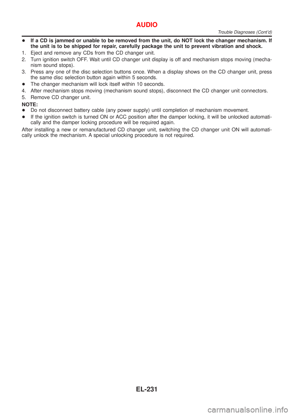
+If a CD is jammed or unable to be removed from the unit, do NOT lock the changer mechanism. If
the unit is to be shipped for repair, carefully package the unit to prevent vibration and shock.
1. Eject and remove any CDs from the CD changer unit.
2. Turn ignition switch OFF. Wait until CD changer unit display is off and mechanism stops moving (mecha-
nism sound stops).
3. Press any one of the disc selection buttons once. When a display shows on the CD changer unit, press
the same disc selection button again within 5 seconds.
+The changer mechanism will lock itself within 10 seconds.
4. After mechanism stops moving (mechanism sound stops), disconnect the CD changer unit connectors.
5. Remove CD changer unit.
NOTE:
+Do not disconnect battery cable (any power supply) until completion of mechanism movement.
+If the ignition switch is turned ON or ACC position after the damper locking, it will be unlocked automati-
cally and the damper locking procedure will be required again.
After installing a new or remanufactured CD changer unit, switching the CD changer unit ON will automati-
cally unlock the mechanism. A special unlocking procedure is not required.
AUDIO
Trouble Diagnoses (Cont'd)
EL-231
Page 2081 of 3051
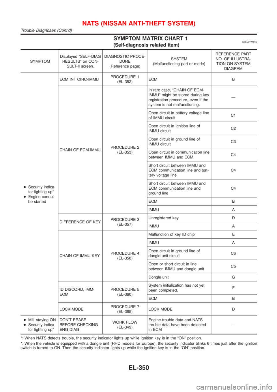
SYMPTOM MATRIX CHART 1NLEL0411S02(Self-diagnosis related item)
SYMPTOMDisplayed ªSELF-DIAG
RESULTSº on CON-
SULT-II screen.DIAGNOSTIC PROCE-
DURE
(Reference page)SYSTEM
(Malfunctioning part or mode)REFERENCE PART
NO. OF ILLUSTRA-
TION ON SYSTEM
DIAGRAM
+Security indica-
tor lighting up*
+Engine cannot
be startedECM INT CIRC-IMMUPROCEDURE 1
(EL-352)ECM B
CHAIN OF ECM-IMMUPROCEDURE 2
(EL-353)In rare case, ªCHAIN OF ECM-
IMMUº might be stored during key
registration procedure, even if the
system is not malfunctioning.Ð
Open circuit in battery voltage line
of IMMU circuitC1
Open circuit in ignition line of
IMMU circuitC2
Open circuit in ground line of
IMMU circuitC3
Open circuit in communication line
between IMMU and ECMC4
Short circuit between IMMU and
ECM communication line and bat-
tery voltage lineC4
Short circuit between IMMU and
ECM communication line and
ground lineC4
ECM B
IMMU A
DIFFERENCE OF KEYPROCEDURE 3
(EL-357)Unregistered key D
IMMU A
CHAIN OF IMMU-KEYPROCEDURE 4
(EL-358)Malfunction of key ID chip E
IMMU A
Open circuit in ground line of
dongle unit circuitC6
Open or short circuit in line
between IMMU and dongle unitC5
Dongle unit G
ID DISCORD, IMM-
ECMPROCEDURE 5
(EL-360)System initialization has not yet
been completed.F
ECM B
LOCK MODEPROCEDURE 7
(EL-365)LOCK MODE D
+MIL staying ON
+Security indica-
tor lighting up*DON'T ERASE
BEFORE CHECKING
ENG DIAGWORK FLOW
(EL-349)Engine trouble data and NATS
trouble data have been detected
in ECMÐ
*: When NATS detects trouble, the security indicator lights up while ignition key is in the ªONº position.
*: When the vehicle is equipped with a dongle unit (RHD models for Europe), the security indicator blinks 6 times just after the ignition
switch is turned to ON. Then the security indicator lights up while the ignition key is in the ªONº position.
NATS (NISSAN ANTI-THEFT SYSTEM)
Trouble Diagnoses (Cont'd)
EL-350
Page 2083 of 3051
SEL152X
DIAGNOSTIC PROCEDURE 1NLEL0411S05Self-diagnostic results:
ªECM INT CIRC-IMMUº displayed on CONSULT-II screen
1. Confirm SELF-DIAGNOSTIC RESULTS ªECM INT CIRC-
IMMUº displayed on CONSULT-II screen. Ref. part No. B.
2. Replace ECM.
3. Perform initialization with CONSULT-II.
For initialization, refer to ªCONSULT-II operation manual
NATSº.
NATS (NISSAN ANTI-THEFT SYSTEM)
Trouble Diagnoses (Cont'd)
EL-352
Page 2084 of 3051
DIAGNOSTIC PROCEDURE 2=NLEL0411S06Self-diagnostic results:
ªCHAIN OF ECM-IMMUº displayed on CONSULT-II screen
1 CONFIRM SELF-DIAGNOSTIC RESULTS
Confirm SELF-DIAGNOSTIC RESULTS ªCHAIN OF ECM-IMMUº displayed on CONSULT-II screen.
NOTE:
In rare case, ªCHAIN OF ECM-IMMUº might be stored during key registration procedure, even if the system is not mal-
functioning.
SEL366X
Is CONSULT-II screen displayed as above?
Ye s©GO TO 2.
No©GO TO SYMPTOM MATRIX CHART 1.
2 CHECK POWER SUPPLY CIRCUIT FOR IMMU
1. Disconnect IMMU connector.
2. Check voltage between terminal 8 of IMMU and ground with CONSULT-II or tester.
NEL695
OK or NG
OK©GO TO 3.
NG©Check the following
+10A fuse Ð (Gasoline engine)
+20A fuse Ð (Diesel engine)
+Harness for open or short between fuse and IMMU connector
Ref. Part No. C1
NATS (NISSAN ANTI-THEFT SYSTEM)
Trouble Diagnoses (Cont'd)
EL-353
Page 2088 of 3051
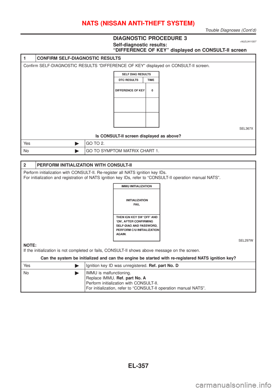
DIAGNOSTIC PROCEDURE 3=NLEL0411S07Self-diagnostic results:
ªDIFFERENCE OF KEYº displayed on CONSULT-II screen
1 CONFIRM SELF-DIAGNOSTIC RESULTS
Confirm SELF-DIAGNOSTIC RESULTS ªDIFFERENCE OF KEYº displayed on CONSULT-II screen.
SEL367X
Is CONSULT-II screen displayed as above?
Ye s©GO TO 2.
No©GO TO SYMPTOM MATRIX CHART 1.
2 PERFORM INITIALIZATION WITH CONSULT-II
Perform initialization with CONSULT-II. Re-register all NATS ignition key IDs.
For initialization and registration of NATS ignition key IDs, refer to ªCONSULT-II operation manual NATSº.
SEL297W
NOTE:
If the initialization is not completed or fails, CONSULT-II shows above message on the screen.
Can the system be initialized and can the engine be started with re-registered NATS ignition key?
Ye s©Ignition key ID was unregistered.Ref. part No. D
No©IMMU is malfunctioning.
Replace IMMU.Ref. part No. A
Perform initialization with CONSULT-II.
For initialization, refer to ªCONSULT-II operation manual NATSº.
NATS (NISSAN ANTI-THEFT SYSTEM)
Trouble Diagnoses (Cont'd)
EL-357
Page 2089 of 3051
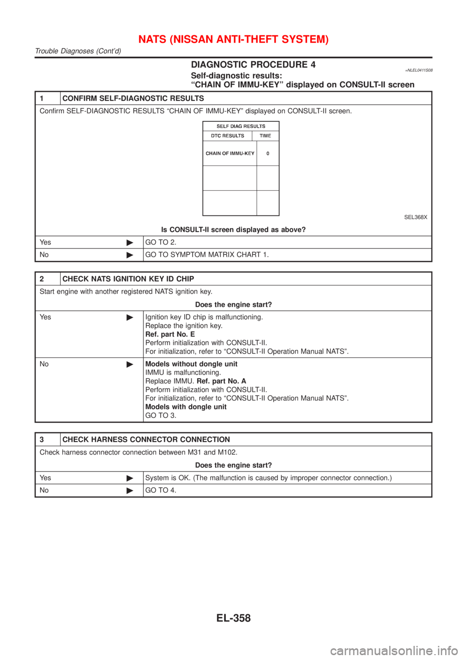
DIAGNOSTIC PROCEDURE 4=NLEL0411S08Self-diagnostic results:
ªCHAIN OF IMMU-KEYº displayed on CONSULT-II screen
1 CONFIRM SELF-DIAGNOSTIC RESULTS
Confirm SELF-DIAGNOSTIC RESULTS ªCHAIN OF IMMU-KEYº displayed on CONSULT-II screen.
SEL368X
Is CONSULT-II screen displayed as above?
Ye s©GO TO 2.
No©GO TO SYMPTOM MATRIX CHART 1.
2 CHECK NATS IGNITION KEY ID CHIP
Start engine with another registered NATS ignition key.
Does the engine start?
Ye s©Ignition key ID chip is malfunctioning.
Replace the ignition key.
Ref. part No. E
Perform initialization with CONSULT-II.
For initialization, refer to ªCONSULT-II Operation Manual NATSº.
No©Models without dongle unit
IMMU is malfunctioning.
Replace IMMU.Ref. part No. A
Perform initialization with CONSULT-II.
For initialization, refer to ªCONSULT-II Operation Manual NATSº.
Models with dongle unit
GO TO 3.
3 CHECK HARNESS CONNECTOR CONNECTION
Check harness connector connection between M31 and M102.
Does the engine start?
Ye s©System is OK. (The malfunction is caused by improper connector connection.)
No©GO TO 4.
NATS (NISSAN ANTI-THEFT SYSTEM)
Trouble Diagnoses (Cont'd)
EL-358
Page 2091 of 3051
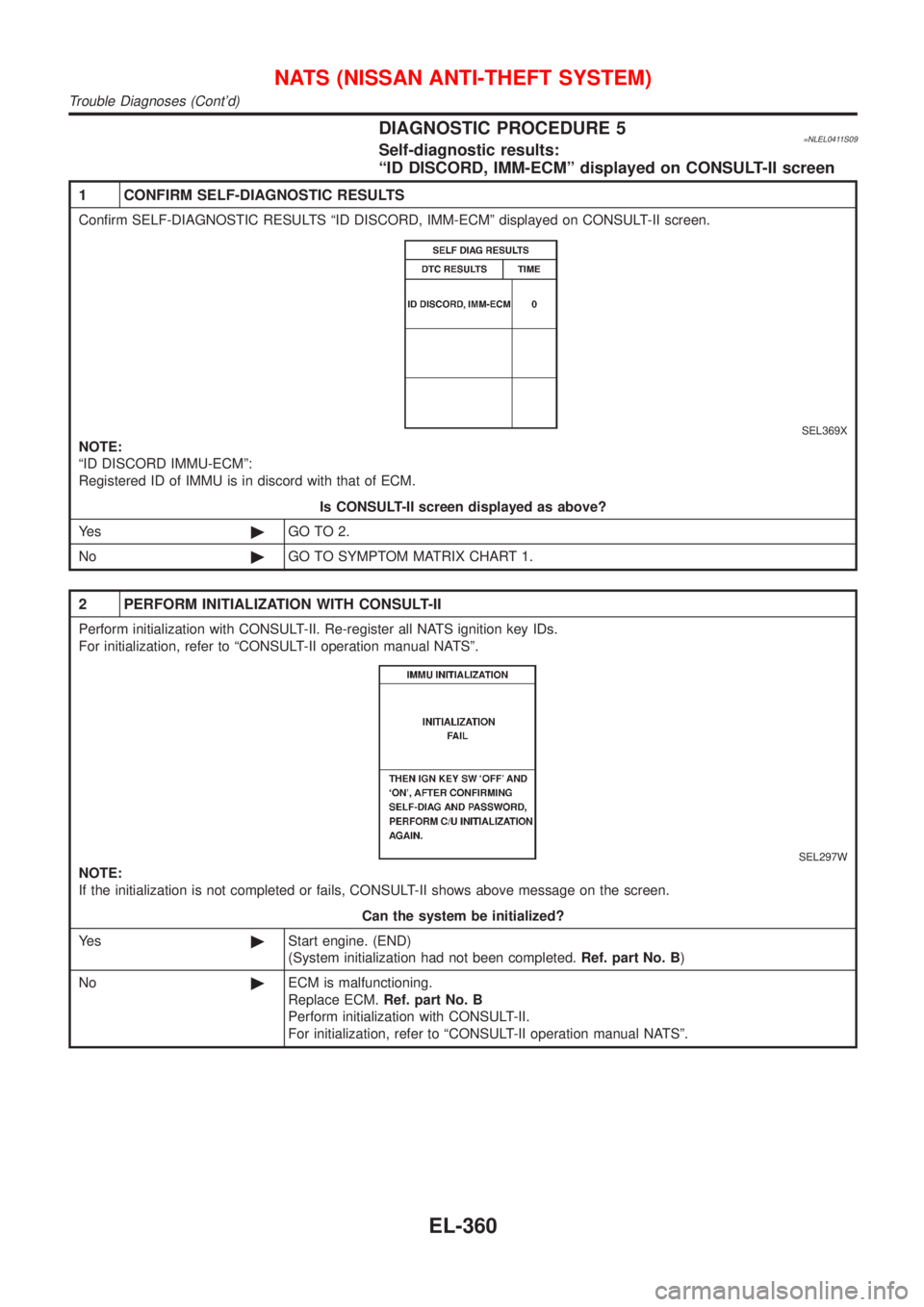
DIAGNOSTIC PROCEDURE 5=NLEL0411S09Self-diagnostic results:
ªID DISCORD, IMM-ECMº displayed on CONSULT-II screen
1 CONFIRM SELF-DIAGNOSTIC RESULTS
Confirm SELF-DIAGNOSTIC RESULTS ªID DISCORD, IMM-ECMº displayed on CONSULT-II screen.
SEL369X
NOTE:
ªID DISCORD IMMU-ECMº:
Registered ID of IMMU is in discord with that of ECM.
Is CONSULT-II screen displayed as above?
Ye s©GO TO 2.
No©GO TO SYMPTOM MATRIX CHART 1.
2 PERFORM INITIALIZATION WITH CONSULT-II
Perform initialization with CONSULT-II. Re-register all NATS ignition key IDs.
For initialization, refer to ªCONSULT-II operation manual NATSº.
SEL297W
NOTE:
If the initialization is not completed or fails, CONSULT-II shows above message on the screen.
Can the system be initialized?
Ye s©Start engine. (END)
(System initialization had not been completed.Ref. part No. B)
No©ECM is malfunctioning.
Replace ECM.Ref. part No. B
Perform initialization with CONSULT-II.
For initialization, refer to ªCONSULT-II operation manual NATSº.
NATS (NISSAN ANTI-THEFT SYSTEM)
Trouble Diagnoses (Cont'd)
EL-360