Page 1326 of 3051
![NISSAN ALMERA TINO 2001 Service Repair Manual TERMI-
NAL
NO.WIRE
COLORITEM CONDITION DATA (DC Voltage)
36 G Ignition check[Engine is running]
+Warm-up condition
+Idle speedApproximately 13V
SEF998V
[Engine is running]
+Engine speed is 2,000 rpmAp NISSAN ALMERA TINO 2001 Service Repair Manual TERMI-
NAL
NO.WIRE
COLORITEM CONDITION DATA (DC Voltage)
36 G Ignition check[Engine is running]
+Warm-up condition
+Idle speedApproximately 13V
SEF998V
[Engine is running]
+Engine speed is 2,000 rpmAp](/manual-img/5/57352/w960_57352-1325.png)
TERMI-
NAL
NO.WIRE
COLORITEM CONDITION DATA (DC Voltage)
36 G Ignition check[Engine is running]
+Warm-up condition
+Idle speedApproximately 13V
SEF998V
[Engine is running]
+Engine speed is 2,000 rpmApproximately 12V
SEF999V
On Board Diagnosis LogicNLEC1912
DTC No. Malfunction is detected when ... Check Items (Possible Cause)
P1320
1320+The ignition signal in the primary circuit is not sent to
ECM during engine cranking or running.+Harness or connectors
(The ignition primary circuit is open or shorted.)
+Power transistor unit.
+Resistor
+Camshaft position sensor
+Camshaft position sensor circuit
DTC Confirmation ProcedureNLEC1913NOTE:
+If ªDTC Confirmation Procedureº has been previously
conducted, always turn ignition switch ªOFFº and wait at least
10 seconds before conducting the next test.
+If DTC P1320 is displayed with P0340, perform trouble
diagnosis for DTC P0340 first. Refer to EC-825.
SEF058Y
With CONSULT-II
1) Turn ignition switch ªONº.
2) Select ªDATA MONITORº mode with CONSULT-II.
3) Start engine and wait at least 4 seconds. (If engine does not
run, turn ignition switch to ªSTARTº at least 5 seconds.)
4) If 1st trip DTC is detected, go to ªDiagnostic Procedureº,
EC-905.
Without CONSULT-II
1) Start engine and wait at least 4 seconds. (If engine does not
run, turn ignition switch to ªSTARTº at least 5 seconds.)
DTC P1320 IGNITION SIGNALSR20DE
ECM Terminals and Reference Value (Cont'd)
EC-901
Page 1348 of 3051
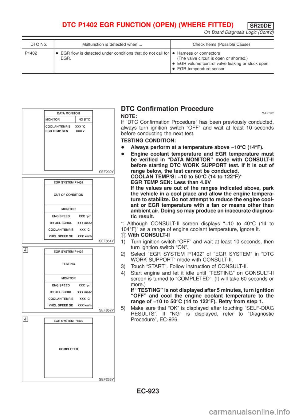
DTC No. Malfunction is detected when ... Check Items (Possible Cause)
P1402+EGR flow is detected under conditions that do not call for
EGR.+Harness or connectors
(The valve circuit is open or shorted.)
+EGR volume control valve leaking or stuck open
+EGR temperature sensor
SEF202Y
SEF851Y
SEF852Y
SEF236Y
DTC Confirmation ProcedureNLEC1637NOTE:
If ªDTC Confirmation Procedureº has been previously conducted,
always turn ignition switch ªOFFº and wait at least 10 seconds
before conducting the next test.
TESTING CONDITION:
+Always perform at a temperature above þ10ÉC (14ÉF).
+Engine coolant temperature and EGR temperature must
be verified in ªDATA MONITORº mode with CONSULT-II
before starting DTC WORK SUPPORT test. If it is out of
range below, the test cannot be conducted.
COOLAN TEMP/S: þ10 to 50ÉC (14 to 122ÉF)*
EGR TEMP SEN: Less than 4.8V
If the values are out of the ranges indicated above, park
the vehicle in a cool place and allow the engine tempera-
ture to stabilize. Do not attempt to reduce the engine cool-
ant or EGR temperature with a fan or means other than
ambient air. Doing so may produce an inaccurate diagnos-
tic result.
*: Although CONSULT-II screen displays ªþ10 to 40ÉC (14 to
104ÉF)º as a range of engine coolant temperature, ignore it.
With CONSULT-II
1) Turn ignition switch ªOFFº and wait at least 10 seconds, then
turn ignition switch ªONº.
2) Select ªEGR SYSTEM P1402º of ªEGR SYSTEMº in ªDTC
WORK SUPPORTº mode with CONSULT-II.
3) Touch ªSTARTº. Follow instruction of CONSULT-II.
4) Start engine and let it idle until ªTESTINGº on CONSULT-II
screen is turned to ªCOMPLETEDº. (It will take 60 seconds or
more.)
If ªTESTINGº is not displayed after 5 minutes, turn ignition
ªOFFº and cool the engine coolant temperature to the
range of þ10 to 50ÉC (14 to 122ÉF). Retry from step 1.
5) Make sure that ªOKº is displayed after touching ªSELF-DIAG
RESULTSº. If ªNGº is displayed, refer to ªDiagnostic
Procedureº, EC-926.
DTC P1402 EGR FUNCTION (OPEN) (WHERE FITTED)SR20DE
On Board Diagnosis Logic (Cont'd)
EC-923
Page 1349 of 3051
SEF947X
With GST
1) Turn ignition switch ªONº and select ªMODE 1º with GST.
2) Check that engine coolant temperature is within the range of
þ10 to 50ÉC (14 to 122ÉF).
3) Check that voltage between ECM terminal 72 (EGR tempera-
ture sensor signal) and ground is less than 4.8V.
4) Start engine and let it idle for at least 60 seconds.
5) Stop engine.
6) Perform from step 1 to 4.
7) Select ªMODE 3º with GST.
8) If DTC is detected, go to ªDiagnostic Procedureº, EC-926.
+When using GST, ªDTC Confirmation Procedureº should
be performed twice as much as when using CONSULT-II
because GST cannot display MODE 7 (1st trip DTC) con-
cerning this diagnosis. Therefore, using CONSULT-II is
recommended.
DTC P1402 EGR FUNCTION (OPEN) (WHERE FITTED)SR20DE
DTC Confirmation Procedure (Cont'd)
EC-924
Page 1489 of 3051
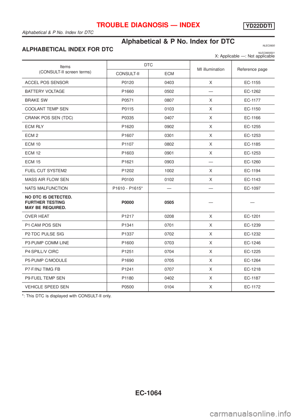
Alphabetical & P No. Index for DTCNLEC0600ALPHABETICAL INDEX FOR DTCNLEC0600S01X: Applicable Ð: Not applicable
Items
(CONSULT-II screen terms)DTC
MI illumination Reference page
CONSULT-II ECM
ACCEL POS SENSOR P0120 0403 X EC-1155
BATTERY VOLTAGE P1660 0502 Ð EC-1262
BRAKE SW P0571 0807 X EC-1177
COOLANT TEMP SEN P0115 0103 X EC-1150
CRANK POS SEN (TDC) P0335 0407 X EC-1166
ECM RLY P1620 0902 X EC-1255
ECM 2 P1607 0301 X EC-1253
ECM 10 P1107 0802 X EC-1185
ECM 12 P1603 0901 X EC-1253
ECM 15 P1621 0903 Ð EC-1260
FUEL CUT SYSTEM2 P1202 1002 X EC-1194
MASS AIR FLOW SEN P0100 0102 X EC-1143
NATS MALFUNCTION P1610 - P1615* Ð Ð EC-1097
NO DTC IS DETECTED.
FURTHER TESTING
MAY BE REQUIRED.P0000 0505ÐÐ
OVER HEAT P1217 0208 X EC-1201
P1´CAM POS SEN P1341 0701 X EC-1239
P2´TDC PULSE SIG P1337 0702 X EC-1232
P3´PUMP COMM LINE P1600 0703 X EC-1246
P4´SPILL/V CIRC P1251 0704 X EC-1225
P5´PUMP C/MODULE P1690 0705 X EC-1264
P7´F/INJ TIMG FB P1241 0707 X EC-1218
P9´FUEL TEMP SEN P1180 0402 X EC-1187
VEHICLE SPEED SEN P0500 0104 X EC-1172
*: This DTC is displayed with CONSULT-II only.
TROUBLE DIAGNOSIS Ð INDEXYD22DDTI
Alphabetical & P No. Index for DTC
EC-1064
Page 1490 of 3051
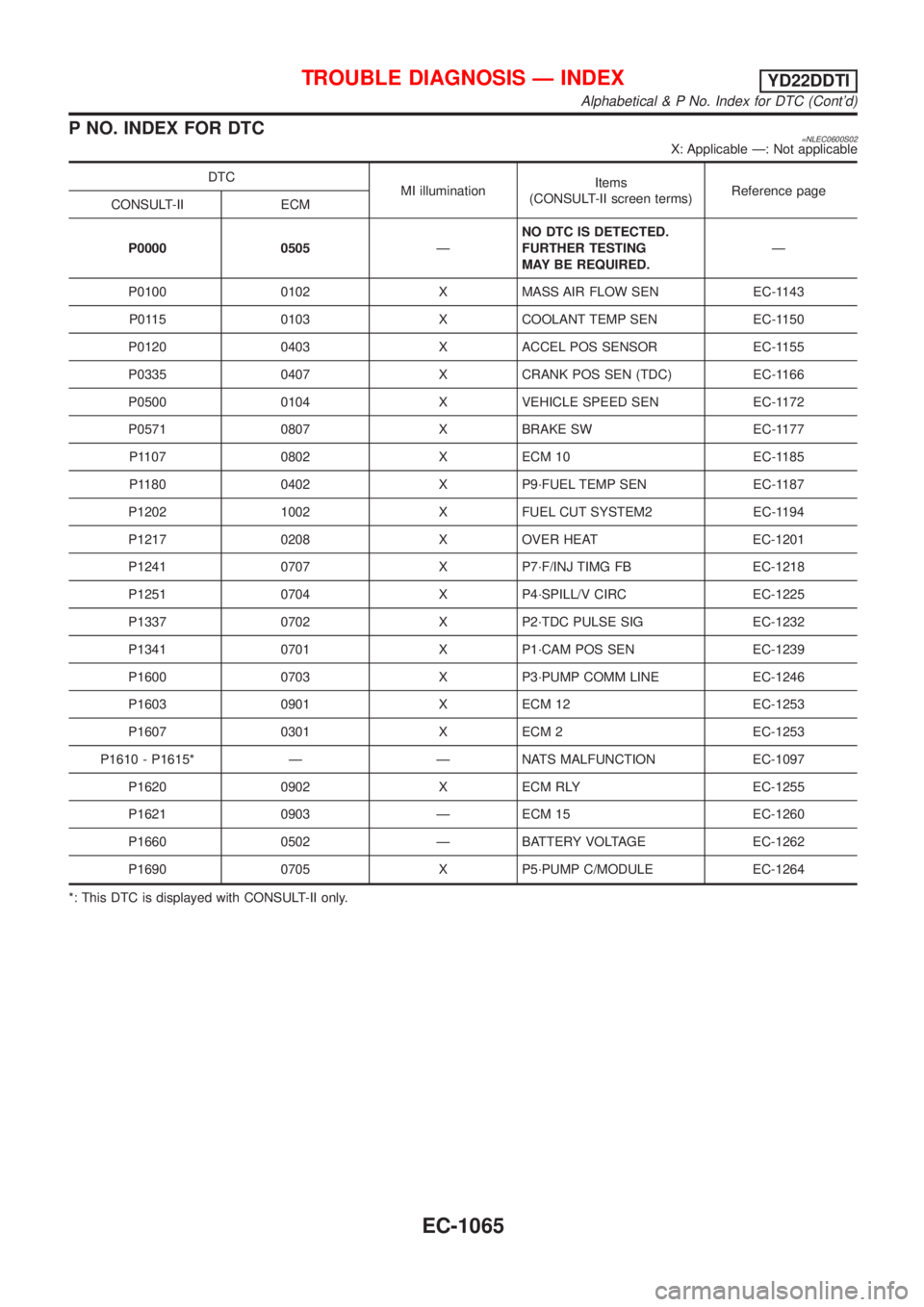
P NO. INDEX FOR DTC=NLEC0600S02X: Applicable Ð: Not applicable
DTC
MI illuminationItems
(CONSULT-II screen terms)Reference page
CONSULT-II ECM
P0000 0505ÐNO DTC IS DETECTED.
FURTHER TESTING
MAY BE REQUIRED.Ð
P0100 0102 X MASS AIR FLOW SEN EC-1143
P0115 0103 X COOLANT TEMP SEN EC-1150
P0120 0403 X ACCEL POS SENSOR EC-1155
P0335 0407 X CRANK POS SEN (TDC) EC-1166
P0500 0104 X VEHICLE SPEED SEN EC-1172
P0571 0807 X BRAKE SW EC-1177
P1107 0802 X ECM 10 EC-1185
P1180 0402 X P9´FUEL TEMP SEN EC-1187
P1202 1002 X FUEL CUT SYSTEM2 EC-1194
P1217 0208 X OVER HEAT EC-1201
P1241 0707 X P7´F/INJ TIMG FB EC-1218
P1251 0704 X P4´SPILL/V CIRC EC-1225
P1337 0702 X P2´TDC PULSE SIG EC-1232
P1341 0701 X P1´CAM POS SEN EC-1239
P1600 0703 X P3´PUMP COMM LINE EC-1246
P1603 0901 X ECM 12 EC-1253
P1607 0301 X ECM 2 EC-1253
P1610 - P1615* Ð Ð NATS MALFUNCTION EC-1097
P1620 0902 X ECM RLY EC-1255
P1621 0903 Ð ECM 15 EC-1260
P1660 0502 Ð BATTERY VOLTAGE EC-1262
P1690 0705 X P5´PUMP C/MODULE EC-1264
*: This DTC is displayed with CONSULT-II only.
TROUBLE DIAGNOSIS Ð INDEXYD22DDTI
Alphabetical & P No. Index for DTC (Cont'd)
EC-1065
Page 1493 of 3051
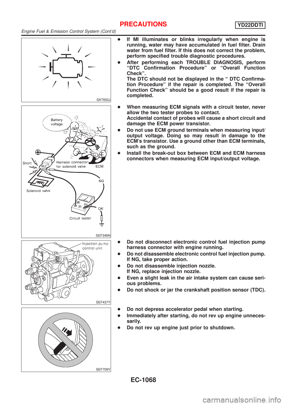
SAT652J
+If MI illuminates or blinks irregularly when engine is
running, water may have accumulated in fuel filter. Drain
water from fuel filter. If this does not correct the problem,
perform specified trouble diagnostic procedures.
+After performing each TROUBLE DIAGNOSIS, perform
ªDTC Confirmation Procedureº or ªOverall Function
Checkº.
The DTC should not be displayed in the ª DTC Confirma-
tion Procedureº if the repair is completed. The ªOverall
Function Checkº should be a good result if the repair is
completed.
SEF348N
+When measuring ECM signals with a circuit tester, never
allow the two tester probes to contact.
Accidental contact of probes will cause a short circuit and
damage the ECM power transistor.
+Do not use ECM ground terminals when measuring input/
output voltage. Doing so may result in damage to the
ECM's transistor. Use a ground other than ECM terminals,
such as the ground.
+Install the break-out box between ECM and ECM harness
connectors when measuring ECM input/output voltage.
SEF437Y
+Do not disconnect electronic control fuel injection pump
harness connector with engine running.
+Do not disassemble electronic control fuel injection pump.
If NG, take proper action.
+Do not disassemble injection nozzle.
If NG, replace injection nozzle.
+Even a slight leak in the air intake system can cause seri-
ous problems.
+Do not shock or jar the crankshaft position sensor (TDC).
SEF709Y
+Do not depress accelerator pedal when starting.
+Immediately after starting, do not rev up engine unneces-
sarily.
+Do not rev up engine just prior to shutdown.
PRECAUTIONSYD22DDTI
Engine Fuel & Emission Control System (Cont'd)
EC-1068
Page 1521 of 3051
DTC and MI Detection LogicNLEC0626When a malfunction is detected, the malfunction (DTC) is stored in the ECM memory.
The MI will light up each time the ECM detects malfunction. For diagnostic items causing the MI to light up,
refer to ªTROUBLE DIAGNOSIS Ð INDEXº, EC-1064.
Diagnostic Trouble Code (DTC)NLEC0627HOW TO READ DTCNLEC0627S01The DTC can be read by the following methods.
Without CONSULT-II
ECM displays the DTC by a set of four digit numbers with MI illumination in the diagnostic test mode II (Self-
diagnostic results). Example: 0103, 0807, 1002, etc.
With CONSULT-II
CONSULT-II displays the DTC in ªSELF-DIAG RESULTSº mode. Examples: P0115, P0571, P1202, etc.
These DTCs are prescribed by ISO15031-6.
(CONSULT-II also displays the malfunctioning component or system.)
+Output of the trouble code means that the indicated circuit has a malfunction. However, in the Mode
II it does not indicate whether the malfunction is still occurring or occurred in the past and returned
to normal.
CONSULT-II can identify them. Therefore, using CONSULT-II (if available) is recommended.
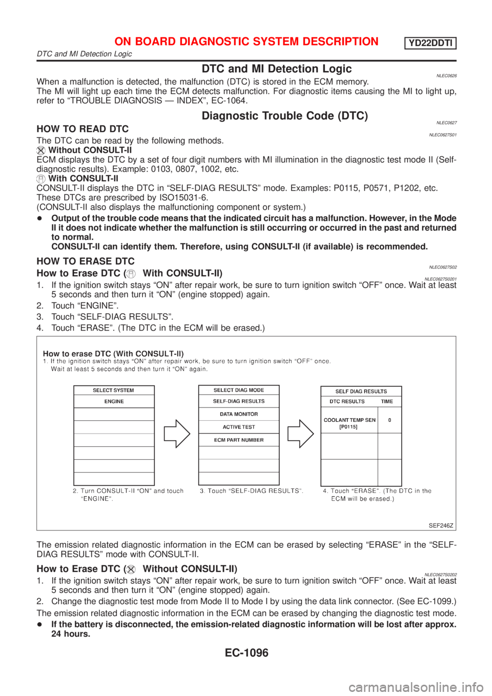
HOW TO ERASE DTCNLEC0627S02How to Erase DTC (With CONSULT-II)NLEC0627S02011. If the ignition switch stays ªONº after repair work, be sure to turn ignition switch ªOFFº once. Wait at least
5 seconds and then turn it ªONº (engine stopped) again.
2. Touch ªENGINEº.
3. Touch ªSELF-DIAG RESULTSº.
4. Touch ªERASEº. (The DTC in the ECM will be erased.)
SEF246Z
The emission related diagnostic information in the ECM can be erased by selecting ªERASEº in the ªSELF-
DIAG RESULTSº mode with CONSULT-II.
How to Erase DTC (Without CONSULT-II)NLEC0627S02021. If the ignition switch stays ªONº after repair work, be sure to turn ignition switch ªOFFº once. Wait at least
5 seconds and then turn it ªONº (engine stopped) again.
2. Change the diagnostic test mode from Mode II to Mode I by using the data link connector. (See EC-1099.)
The emission related diagnostic information in the ECM can be erased by changing the diagnostic test mode.
+If the battery is disconnected, the emission-related diagnostic information will be lost after approx.
24 hours.
ON BOARD DIAGNOSTIC SYSTEM DESCRIPTIONYD22DDTI
DTC and MI Detection Logic
EC-1096
Page 1526 of 3051
Relationship Between MI, DTC, CONSULT-II and Driving PatternsNLEC0628S07
SEF879Y
*1: When a malfunction is detected,
MI will light up.
*2: When the same malfunction is
detected in two consecutive driv-
ing patterns, MI will stay lit up.
*3: MI will go off after vehicle is driven
three times without any malfunc-
tions.*4: When a malfunction is detected
for the first time, the DTC will be
stored in ECM.
*5: The DTC will not be displayed any
longer after vehicle is driven 40
times without the same malfunc-
tion. (The DTC still remain in
ECM.)*6: Other screens except SELF-DIAG-
NOSTIC RESULTS & DATA
MONITOR (AUTO TRIG) cannot
display the malfunction. DATA
MONITOR (AUTO TRIG) can dis-
play the malfunction at the
moment it is detected.
ON BOARD DIAGNOSTIC SYSTEM DESCRIPTIONYD22DDTI
Malfunction Indicator (MI) (Cont'd)
EC-1101