2001 NISSAN ALMERA TINO fuel type
[x] Cancel search: fuel typePage 1457 of 3051
System DescriptionNLEC1865
Sensor Input Signal to ECMECM func-
tionActuator
Camshaft position sensor Engine speed
Fuel pump
controlFuel pump relay
Ignition switch Ignition signal and start signal
The ECM activates the fuel pump for several seconds after the ignition switch is turned on to improve engine
startability. If the ECM receives a 180É signal from the camshaft position sensor, it knows that the engine is
rotating, and causes the pump to perform. If the 180É signal is not received when the ignition switch is on, the
engine stalls. The ECM stops pump operation and prevents battery discharging, thereby improving safety. The
ECM does not directly drive the fuel pump. It controls the ON/OFF fuel pump relay, which in turn controls the
fuel pump.
Condition Fuel pump operation
Ignition switch is turned to ON. Operates for 1 second
Engine running and cranking Operates
When engine is stopped (Signal is not sent from crankshaft position sensor
and camshaft position sensor.)Stops in 1.5 seconds
Except as shown aboveStops
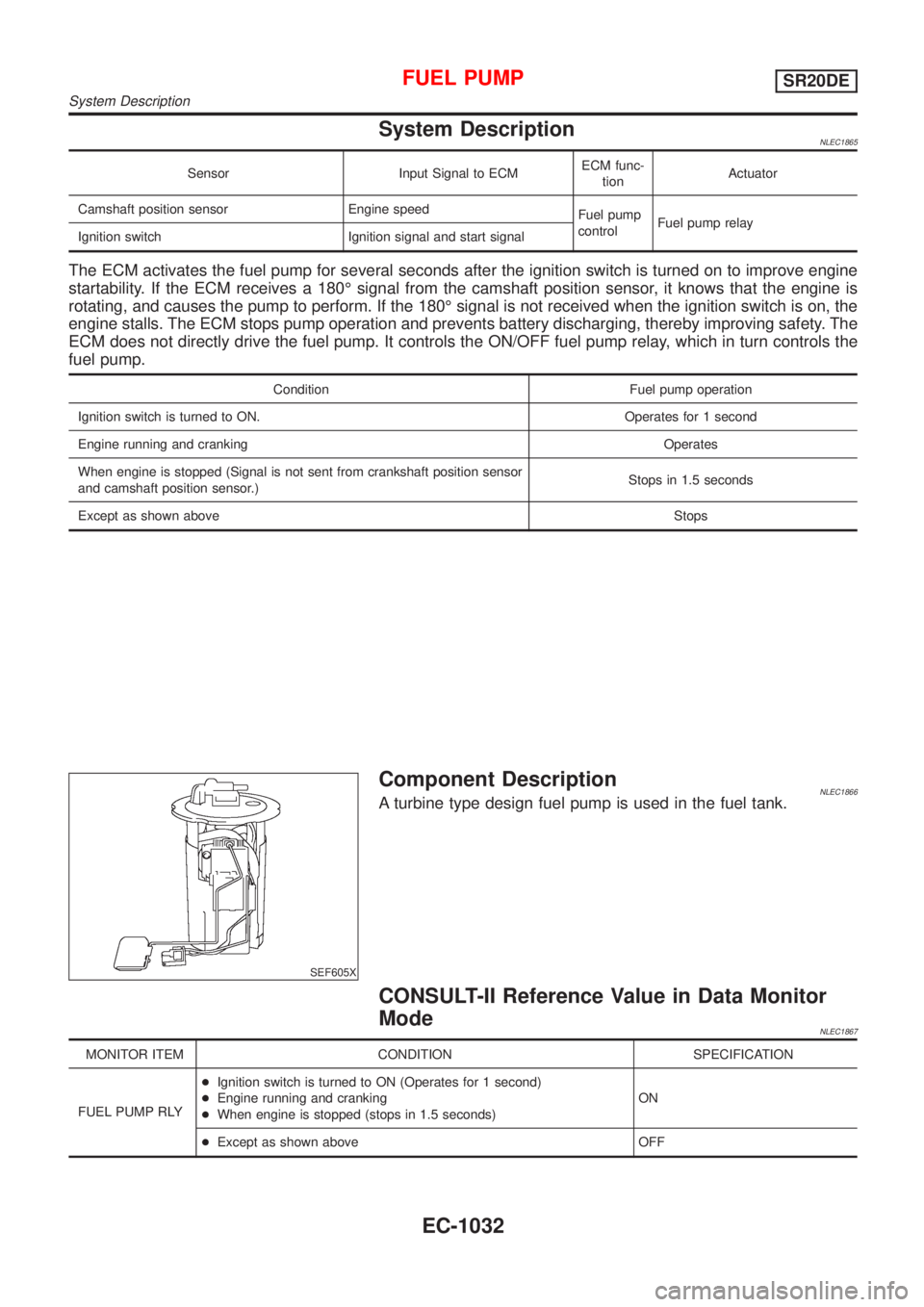
SEF605X
Component DescriptionNLEC1866A turbine type design fuel pump is used in the fuel tank.
CONSULT-II Reference Value in Data Monitor
Mode
NLEC1867
MONITOR ITEM CONDITION SPECIFICATION
FUEL PUMP RLY+Ignition switch is turned to ON (Operates for 1 second)
+Engine running and cranking
+When engine is stopped (stops in 1.5 seconds)ON
+Except as shown above OFF
FUEL PUMPSR20DE
System Description
EC-1032
Page 1504 of 3051
Fuel Injection Control System
DESCRIPTIONNLEC0612System DescriptionNLEC0612S01Three types of fuel injection control are provided to accommodate engine operating conditions; normal control,
idle control and start control. The ECM determines the appropriate fuel injection control. Under each control,
the amount of fuel injected is compensated to improve engine performance.
Pulse signals are exchanged between ECM and electronic control fuel injection pump (control unit is built-in).
The fuel injection pump control unit performs duty control on the spill valve (built into the fuel injection pump)
according to the input signals to compensate the amount of fuel injected to the preset value.
Start ControlNLEC0612S02Input/Output Signal ChartNLEC0612S0201
Sensor Input Signal to ECM ECM Function Actuator
Engine coolant temperature sensor Engine coolant temperature
Fuel injection
control (start
control)Electronic control fuel
injection pump Crankshaft position sensor (TDC) Engine speed
Ignition switch Start signal
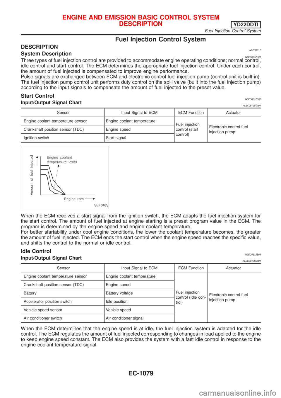
SEF648S
When the ECM receives a start signal from the ignition switch, the ECM adapts the fuel injection system for
the start control. The amount of fuel injected at engine starting is a preset program value in the ECM. The
program is determined by the engine speed and engine coolant temperature.
For better startability under cool engine conditions, the lower the coolant temperature becomes, the greater
the amount of fuel injected. The ECM ends the start control when the engine speed reaches the specific value,
and shifts the control to the normal or idle control.
Idle ControlNLEC0612S03Input/Output Signal ChartNLEC0612S0301
Sensor Input Signal to ECM ECM Function Actuator
Engine coolant temperature sensor Engine coolant temperature
Fuel injection
control (Idle con-
trol)Electronic control fuel
injection pump Crankshaft position sensor (TDC) Engine speed
Battery Battery voltage
Accelerator position switch Idle position
Vehicle speed sensor Vehicle speed
Air conditioner switch Air conditioner signal
When the ECM determines that the engine speed is at idle, the fuel injection system is adapted for the idle
control. The ECM regulates the amount of fuel injected corresponding to changes in load applied to the engine
to keep engine speed constant. The ECM also provides the system with a fast idle control in response to the
engine coolant temperature signal.
ENGINE AND EMISSION BASIC CONTROL SYSTEM
DESCRIPTION
YD22DDTI
Fuel Injection Control System
EC-1079
Page 1514 of 3051
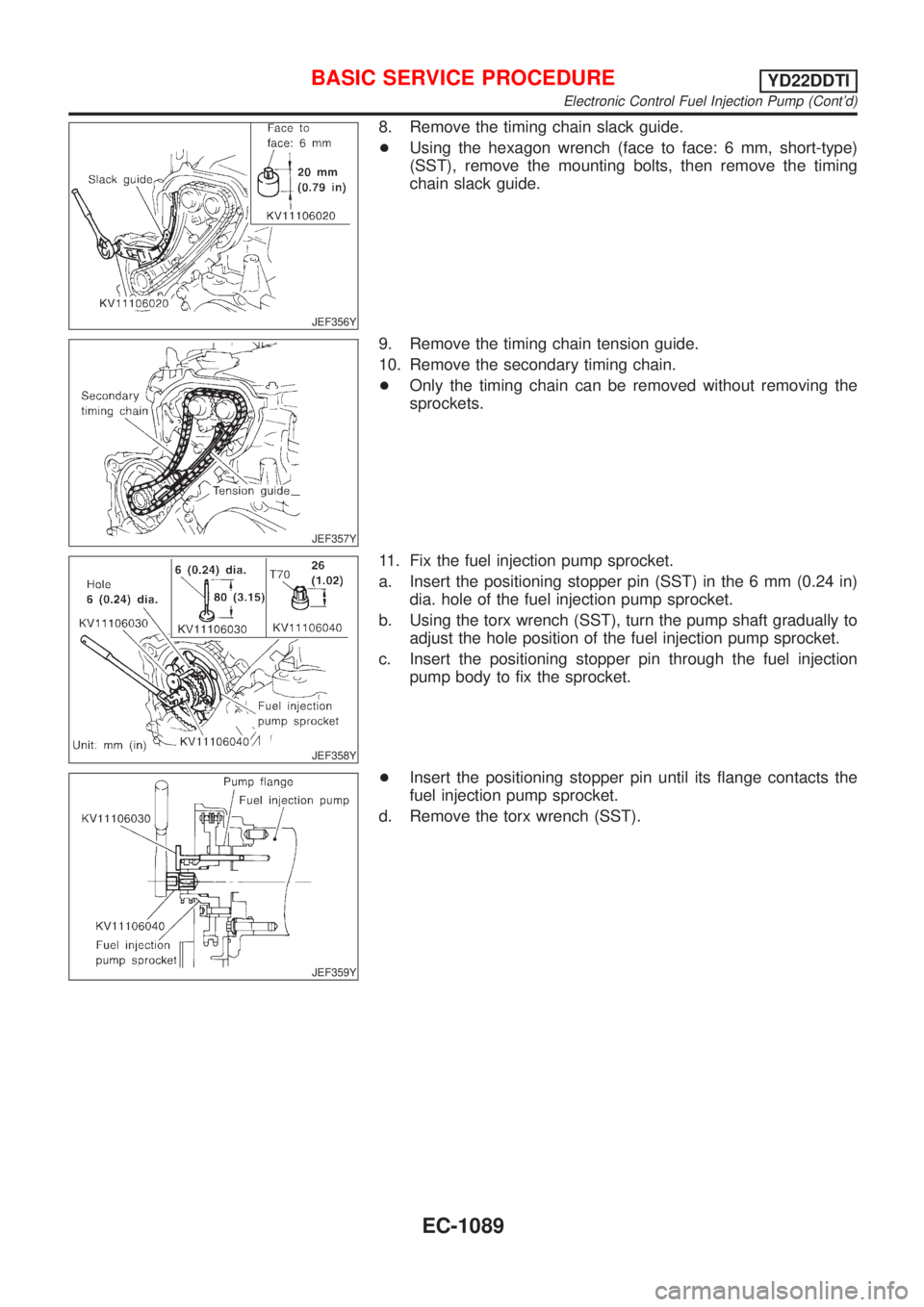
JEF356Y
8. Remove the timing chain slack guide.
+Using the hexagon wrench (face to face: 6 mm, short-type)
(SST), remove the mounting bolts, then remove the timing
chain slack guide.
JEF357Y
9. Remove the timing chain tension guide.
10. Remove the secondary timing chain.
+Only the timing chain can be removed without removing the
sprockets.
JEF358Y
11. Fix the fuel injection pump sprocket.
a. Insert the positioning stopper pin (SST) in the 6 mm (0.24 in)
dia. hole of the fuel injection pump sprocket.
b. Using the torx wrench (SST), turn the pump shaft gradually to
adjust the hole position of the fuel injection pump sprocket.
c. Insert the positioning stopper pin through the fuel injection
pump body to fix the sprocket.
JEF359Y
+Insert the positioning stopper pin until its flange contacts the
fuel injection pump sprocket.
d. Remove the torx wrench (SST).
BASIC SERVICE PROCEDUREYD22DDTI
Electronic Control Fuel Injection Pump (Cont'd)
EC-1089
Page 1515 of 3051
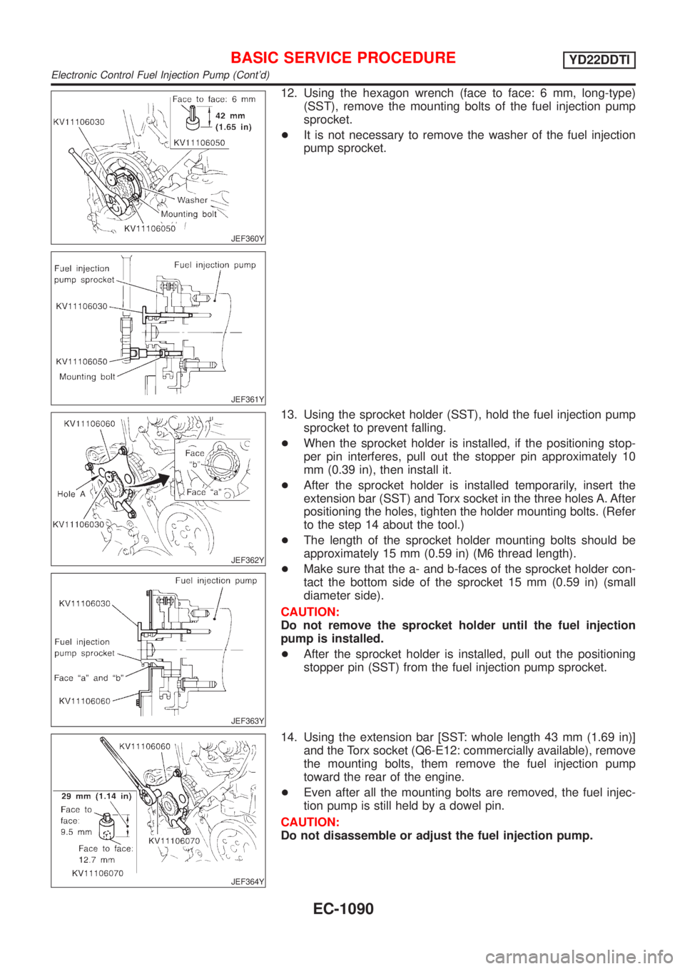
JEF360Y
JEF361Y
12. Using the hexagon wrench (face to face: 6 mm, long-type)
(SST), remove the mounting bolts of the fuel injection pump
sprocket.
+It is not necessary to remove the washer of the fuel injection
pump sprocket.
JEF362Y
JEF363Y
13. Using the sprocket holder (SST), hold the fuel injection pump
sprocket to prevent falling.
+When the sprocket holder is installed, if the positioning stop-
per pin interferes, pull out the stopper pin approximately 10
mm (0.39 in), then install it.
+After the sprocket holder is installed temporarily, insert the
extension bar (SST) and Torx socket in the three holes A. After
positioning the holes, tighten the holder mounting bolts. (Refer
to the step 14 about the tool.)
+The length of the sprocket holder mounting bolts should be
approximately 15 mm (0.59 in) (M6 thread length).
+Make sure that the a- and b-faces of the sprocket holder con-
tact the bottom side of the sprocket 15 mm (0.59 in) (small
diameter side).
CAUTION:
Do not remove the sprocket holder until the fuel injection
pump is installed.
+After the sprocket holder is installed, pull out the positioning
stopper pin (SST) from the fuel injection pump sprocket.
JEF364Y
14. Using the extension bar [SST: whole length 43 mm (1.69 in)]
and the Torx socket (Q6-E12: commercially available), remove
the mounting bolts, them remove the fuel injection pump
toward the rear of the engine.
+Even after all the mounting bolts are removed, the fuel injec-
tion pump is still held by a dowel pin.
CAUTION:
Do not disassemble or adjust the fuel injection pump.
BASIC SERVICE PROCEDUREYD22DDTI
Electronic Control Fuel Injection Pump (Cont'd)
EC-1090
Page 1517 of 3051
JEF360Y
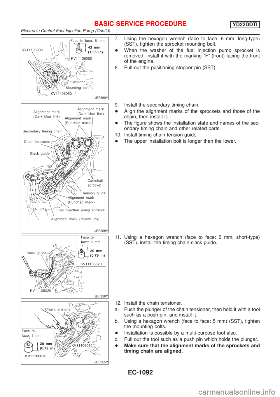
7. Using the hexagon wrench (face to face: 6 mm, long-type)
(SST), tighten the sprocket mounting bolt.
+When the washer of the fuel injection pump sprocket is
removed, install it with the marking ªFº (front) facing the front
of the engine.
8. Pull out the positioning stopper pin (SST).
JEF368Y
9. Install the secondary timing chain.
+Align the alignment marks of the sprockets and those of the
chain, then install it.
+The figure shows the installation state and names of the sec-
ondary timing chain and other related parts.
10. Install timing chain tension guide.
+The upper installation bolt is longer than the lower.
JEF356Y
11. Using a hexagon wrench (face to face: 6 mm, short-type)
(SST), install the timing chain slack guide.
JEF355Y
12. Install the chain tensioner.
a. Push the plunger of the chain tensioner, then hold it with a tool
such as a push pin, and install it.
b. Using a hexagon wrench (face to face: 5 mm) (SST), tighten
the mounting bolts.
+Installation is possible by a multi-purpose tool also.
c. Pull out the tool such as a push pin which holds the plunger.
+Make sure that the alignment marks of the sprockets and
timing chain are aligned.
BASIC SERVICE PROCEDUREYD22DDTI
Electronic Control Fuel Injection Pump (Cont'd)
EC-1092
Page 1895 of 3051
NEL664
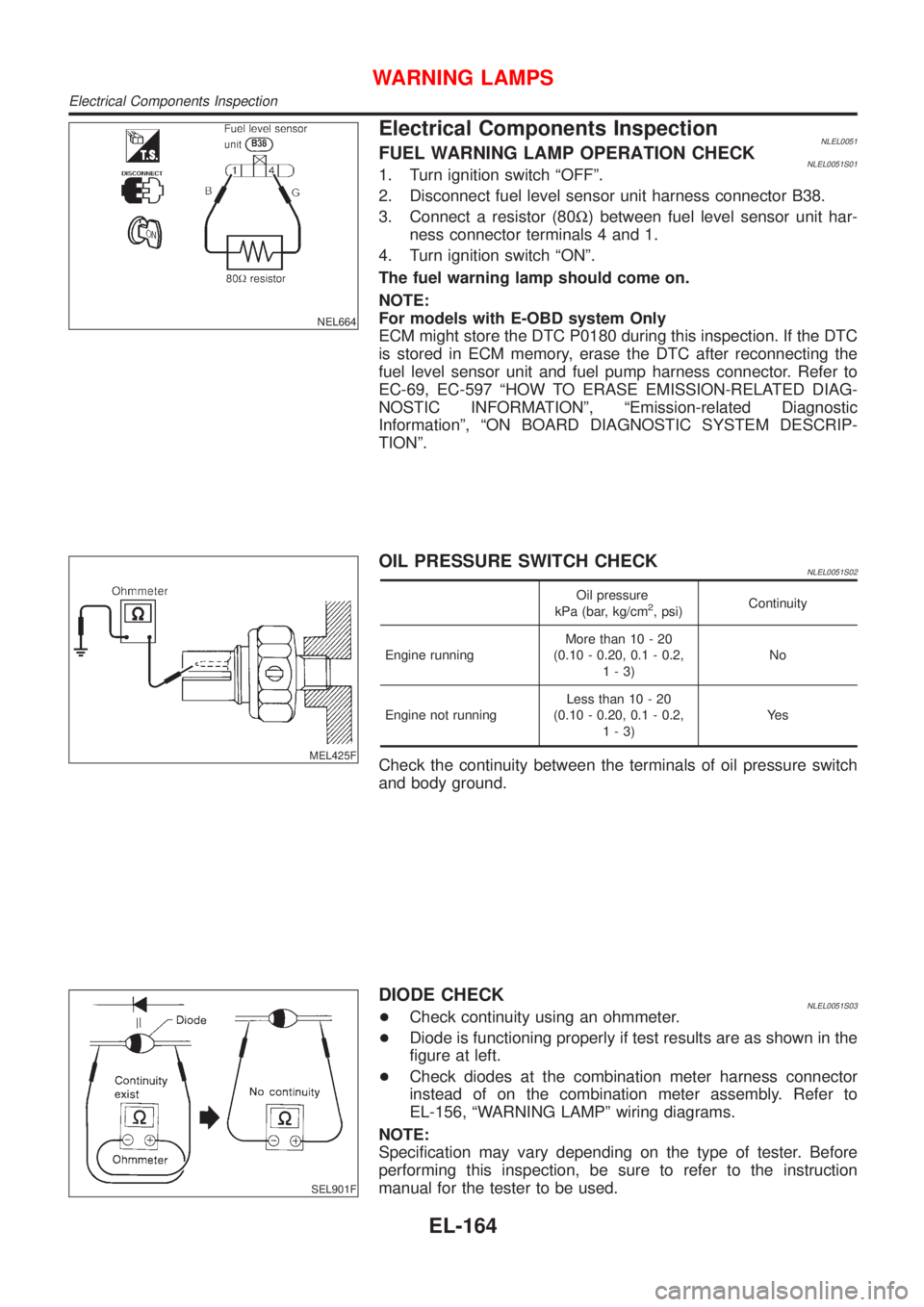
Electrical Components InspectionNLEL0051FUEL WARNING LAMP OPERATION CHECKNLEL0051S011. Turn ignition switch ªOFFº.
2. Disconnect fuel level sensor unit harness connector B38.
3. Connect a resistor (80W) between fuel level sensor unit har-
ness connector terminals 4 and 1.
4. Turn ignition switch ªONº.
The fuel warning lamp should come on.
NOTE:
For models with E-OBD system Only
ECM might store the DTC P0180 during this inspection. If the DTC
is stored in ECM memory, erase the DTC after reconnecting the
fuel level sensor unit and fuel pump harness connector. Refer to
EC-69, EC-597 ªHOW TO ERASE EMISSION-RELATED DIAG-
NOSTIC INFORMATIONº, ªEmission-related Diagnostic
Informationº, ªON BOARD DIAGNOSTIC SYSTEM DESCRIP-
TIONº.
MEL425F
OIL PRESSURE SWITCH CHECKNLEL0051S02
Oil pressure
kPa (bar, kg/cm2, psi)Continuity
Engine runningMore than 10 - 20
(0.10 - 0.20, 0.1 - 0.2,
1-3)No
Engine not runningLess than 10 - 20
(0.10 - 0.20, 0.1 - 0.2,
1-3)Ye s
Check the continuity between the terminals of oil pressure switch
and body ground.
SEL901F
DIODE CHECKNLEL0051S03+Check continuity using an ohmmeter.
+Diode is functioning properly if test results are as shown in the
figure at left.
+Check diodes at the combination meter harness connector
instead of on the combination meter assembly. Refer to
EL-156, ªWARNING LAMPº wiring diagrams.
NOTE:
Specification may vary depending on the type of tester. Before
performing this inspection, be sure to refer to the instruction
manual for the tester to be used.
WARNING LAMPS
Electrical Components Inspection
EL-164
Page 2260 of 3051
PISTON RING END GAP........................................135
CONNECTING ROD BEND AND TORSION.............136
CYLINDER BLOCK DISTORTION AND WEAR.........136
PISTON-TO-BORE CLEARANCE............................137
CRANKSHAFT.......................................................138
BEARING CLEARANCE.........................................138
CONNECTING ROD BUSHING CLEARANCE
(SMALL END)
........................................................141
REPLACEMENT OF CONNECTING ROD
BUSHING (SMALL END)
........................................141
REPLACEMENT OF PILOT CONVERTER (CVT).....141
DRIVE PLATE RUNOUT........................................142
Assembly .................................................................142
PISTON................................................................142
CRANKSHAFT.......................................................143
SERVICE DATA AND SPECIFICATIONS (SDS).......146
General Specifications .............................................146
Compression Pressure ............................................146
Cylinder Head ..........................................................146
Valve ........................................................................147
VALVE..................................................................147
VALVE SPRING.....................................................147
HYDRAULIC LASH ADJUSTER (HLA).....................147
VALVE GUIDE.......................................................148
VALVE SHIM CLEARANCE ADJUSTMENT..............148
AVAILABLE SHIM..................................................149
VALVE SEAT.........................................................150
Camshaft and Camshaft Bearing ............................151
Cylinder Block ..........................................................152
Piston, Piston Ring and Piston Pin .........................153
PISTON................................................................153
PISTON RING.......................................................153
PISTON PIN..........................................................153
Connecting Rod .......................................................154
Crankshaft................................................................155
Main Bearing............................................................156
STANDARD...........................................................156
UNDERSIZE..........................................................156
Connecting Rod Bearing .........................................156
STANDARD SIZE..................................................156
UNDERSIZE..........................................................156
Bearing Clearance ...................................................157
Miscellaneous Components.....................................157
YD
PRECAUTIONS...........................................................158
Parts Requiring Angular Tightening .........................158
Liquid Gasket Application Procedure ......................158
PREPARATION...........................................................159
Special Service Tools ..............................................159
Commercial Service Tools .......................................161
NOISE, VIBRATION AND HARSHNESS (NVH)
TROUBLESHOOTING.................................................163
NVH Troubleshooting - Engine Noise .....................163MEASUREMENT OF COMPRESSION PRESSURE..164
DRIVE BELTS..............................................................166
Inspection.................................................................166
Adjustment ...............................................................166
AIR CONDITIONER COMPRESSOR BELT..............167
ALTERNATOR & WATER PUMP BELT...................167
Removal ...................................................................167
Installation ................................................................168
AIR CLEANER.............................................................169
Changing Air Cleaner Filter .....................................169
VISCOUS PAPER TYPE.........................................169
OIL PAN.......................................................................170
Components.............................................................170
Removal ...................................................................170
Installation ................................................................172
TIMING CHAIN............................................................175
Secondary Timing Chain .........................................175
REMOVAL.............................................................175
INSPECTION.........................................................177
INSTALLATION......................................................177
Primary Timing Chain ..............................................180
REMOVAL.............................................................181
INSPECTION.........................................................183
INSTALLATION......................................................183
INTAKE MANIFOLD....................................................188
Removal and Installation .........................................188
PREPARATIVE WORK...........................................188
FUEL PIPING........................................................189
INTAKE MANIFOLD...............................................189
EGR VOLUME CONTROL VALVE...........................189
WATER HOSE.......................................................189
Inspection.................................................................190
INTAKE MANIFOLD...............................................190
SWIRL CONTROL VALVE......................................190
CATALYST..................................................................191
Removal and Installation .........................................191
PREPARATIVE WORK...........................................191
THREE WAY CATALYST.......................................191
GUSSET...............................................................192
EXHAUST MANIFOLD, TURBOCHARGER...............193
Removal and Installation .........................................193
PREPARATIVE WORK...........................................193
EXHAUST MANIFOLD AND TURBOCHARGER.......193
EXHAUST MANIFOLD GASKET.............................194
Disassembly and Assembly .....................................194
TURBOCHARGER.................................................194
Inspection.................................................................195
EXHAUST MANIFOLD...........................................195
TURBOCHARGER.................................................195
ROCKER COVER........................................................198
Removal and Installation .........................................198
PREPARATIVE WORK...........................................198
ROCKER COVER..................................................198
CYLINDER HEAD........................................................200
CONTENTS(Cont'd)
EM-3
Page 2441 of 3051
JEM140G
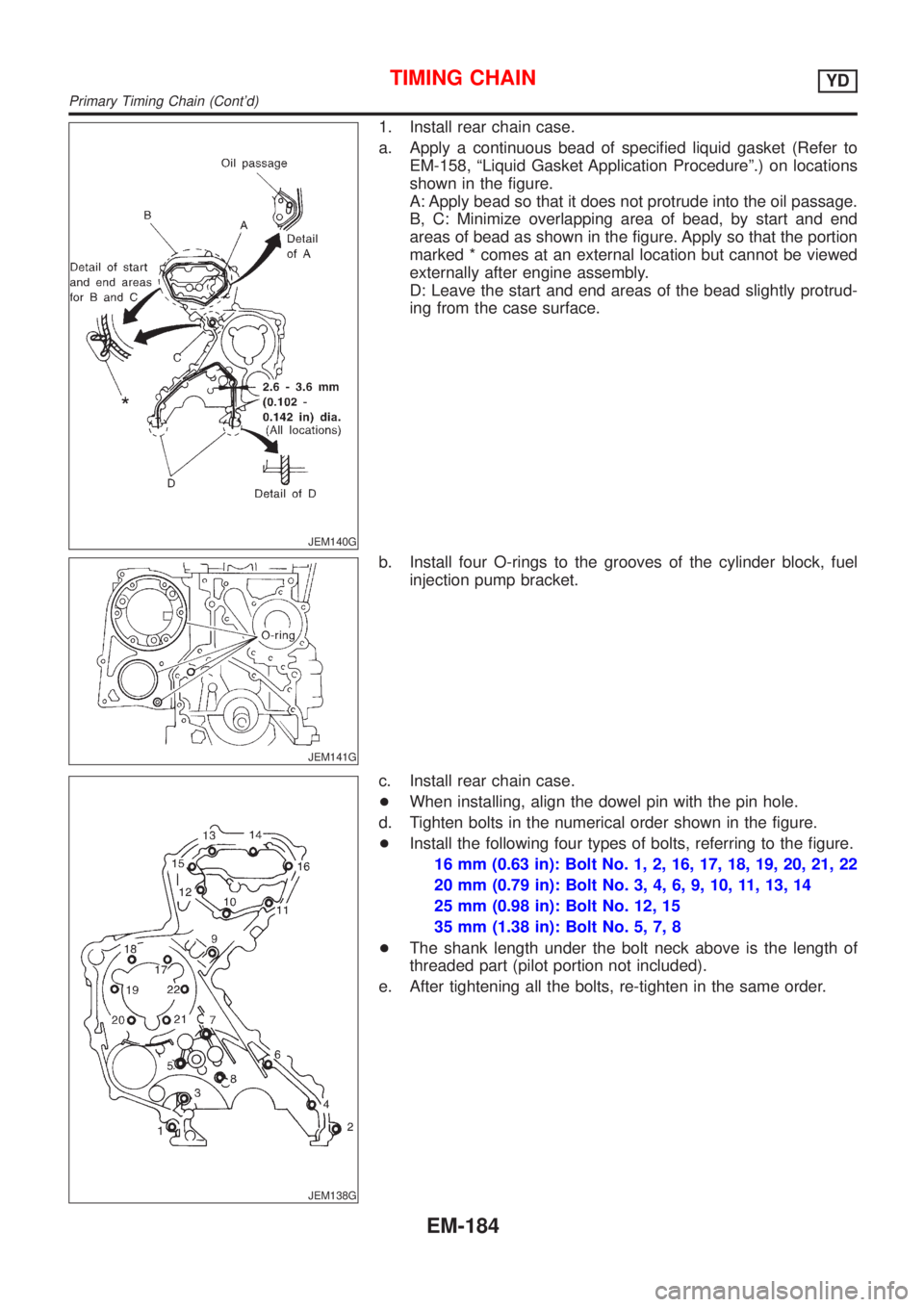
1. Install rear chain case.
a. Apply a continuous bead of specified liquid gasket (Refer to
EM-158, ªLiquid Gasket Application Procedureº.) on locations
shown in the figure.
A: Apply bead so that it does not protrude into the oil passage.
B, C: Minimize overlapping area of bead, by start and end
areas of bead as shown in the figure. Apply so that the portion
marked * comes at an external location but cannot be viewed
externally after engine assembly.
D: Leave the start and end areas of the bead slightly protrud-
ing from the case surface.
JEM141G
b. Install four O-rings to the grooves of the cylinder block, fuel
injection pump bracket.
JEM138G
c. Install rear chain case.
+When installing, align the dowel pin with the pin hole.
d. Tighten bolts in the numerical order shown in the figure.
+Install the following four types of bolts, referring to the figure.
16 mm (0.63 in): Bolt No. 1, 2, 16, 17, 18, 19, 20, 21, 22
20 mm (0.79 in): Bolt No. 3, 4, 6, 9, 10, 11, 13, 14
25 mm (0.98 in): Bolt No. 12, 15
35 mm (1.38 in): Bolt No. 5, 7, 8
+The shank length under the bolt neck above is the length of
threaded part (pilot portion not included).
e. After tightening all the bolts, re-tighten in the same order.
TIMING CHAINYD
Primary Timing Chain (Cont'd)
EM-184