2001 NISSAN ALMERA TINO ECU
[x] Cancel search: ECUPage 1020 of 3051
The emission-related diagnostic information can be erased by selecting ªERASEº in the ªSELF-DIAG
RESULTSº mode with CONSULT-II.
How to Erase DTC (
With GST)
NOTE:
If the DTC is not for CVT related items (see EC-550), skip step 2.
1) If the ignition switch stays ªONº after repair work, be sure to turn ignition switch ªOFFº once. Wait at least
10 seconds and then turn it ªONº (engine stopped) again.
2) Perform ªSELF-DIAGNOSTIC PROCEDURE (Without CONSULT-II)º in AT section titled ªTROUBLE
DIAGNOSISº, ªSelf-diagnosisº. (The engine warm-up step can be skipped when performing the diagnosis
only to erase the DTC.)
3) Select Mode 4 with GST (Generic Scan Tool).
The emission-related diagnostic information can be erased by selecting Mode 4 with GST (Generic Scan Tool).
NOTE:
+If the battery is disconnected, the emission-related diagnostic information will be lost after approx.
24 hours.
+Erasing the emission-related diagnostic information using CONSULT-II or GST is easier and
quicker than switching the mode using the data link connector.
+The following data are cleared when the ECM memory is erased.
1) Diagnostic trouble codes
2) 1st trip diagnostic trouble codes
3) Freeze frame data
4) 1st trip freeze frame data
5) System readiness test (SRT) codes
6) Test values
7) Distance traveled while MI is activated
8) Others
Actual work procedures are explained using a DTC as an example. Be careful so that not only the DTC, but
all of the data listed above, are cleared from the ECM memory during work procedures.
MODELS WITHOUT EURO-OBD SYSTEMNLEC1361S02DTC and 1st Trip DTCNLEC1361S0201The 1st trip DTC (whose number is the same as the DTC number) is displayed for the latest self-diagnostic
result obtained. If the ECM memory was cleared previously, and the 1st trip DTC did not reoccur, the 1st trip
DTC will not be displayed.
If a malfunction is detected during the 1st trip, the 1st trip DTC is stored in the ECM memory. If the same mal-
function is not detected in the 2nd trip (meeting the required driving pattern), the 1st trip DTC is cleared from
the ECM memory. If the same malfunction is detected in the 2nd trip, both the 1st trip DTC and DTC are stored
in the ECM memory. In other words, the DTC is stored in the ECM memory when the same malfunction occurs
in two consecutive trips. If a 1st trip DTC is stored and a non-diagnostic operation is performed between the
1st and 2nd trips, only the 1st trip DTC will continue to be stored. For fail-safe items, the DTC is stored in the
ECM memory even in the 1st trip.
Procedures for clearing the DTC and the 1st trip DTC from the ECM memory are described in ªHow to Erase
Emission-related Diagnostic Informationº, EC-596.
When a (1st trip) DTC is detected, check, print out or write down and erase (1st trip) DTC and Freeze Frame
data as specified in ªWork Flowº procedure Step II, refer to EC-621. Then perform ªDTC Confirmation Proce-
dureº or ªOverall Function Checkº to try to duplicate the problem. If the malfunction is duplicated, the item
requires repair.
How to Read DTC and 1st Trip DTC
DTC and 1st trip DTC can be read by the following methods.
Without CONSULT-II
ECM displays the DTC by a set of four digit numbers with MI illumination in the diagnostic test mode II (Self-
diagnostic results). Example: 0100, 0115, 0340, 1335, etc.
With CONSULT-II
CONSULT-II displays the DTC in ªSELF-DIAG RESULTSº mode. Examples: P0100, P0115, P0340, P1335,
etc.
(CONSULT-II also displays the malfunctioning component or system.)
+1st trip DTC No. is the same as DTC No.
ON BOARD DIAGNOSTIC SYSTEM DESCRIPTIONSR20DE
Emission-related Diagnostic Information (Cont'd)
EC-595
Page 1022 of 3051
SEF993X
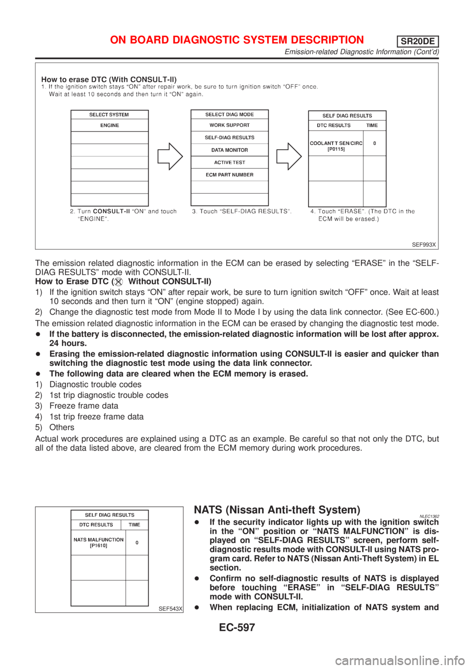
The emission related diagnostic information in the ECM can be erased by selecting ªERASEº in the ªSELF-
DIAG RESULTSº mode with CONSULT-II.
How to Erase DTC (
Without CONSULT-II)
1) If the ignition switch stays ªONº after repair work, be sure to turn ignition switch ªOFFº once. Wait at least
10 seconds and then turn it ªONº (engine stopped) again.
2) Change the diagnostic test mode from Mode II to Mode I by using the data link connector. (See EC-600.)
The emission related diagnostic information in the ECM can be erased by changing the diagnostic test mode.
+If the battery is disconnected, the emission-related diagnostic information will be lost after approx.
24 hours.
+Erasing the emission-related diagnostic information using CONSULT-II is easier and quicker than
switching the diagnostic test mode using the data link connector.
+The following data are cleared when the ECM memory is erased.
1) Diagnostic trouble codes
2) 1st trip diagnostic trouble codes
3) Freeze frame data
4) 1st trip freeze frame data
5) Others
Actual work procedures are explained using a DTC as an example. Be careful so that not only the DTC, but
all of the data listed above, are cleared from the ECM memory during work procedures.
SEF543X
NATS (Nissan Anti-theft System)NLEC1362+If the security indicator lights up with the ignition switch
in the ªONº position or ªNATS MALFUNCTIONº is dis-
played on ªSELF-DIAG RESULTSº screen, perform self-
diagnostic results mode with CONSULT-II using NATS pro-
gram card. Refer to NATS (Nissan Anti-Theft System) in EL
section.
+Confirm no self-diagnostic results of NATS is displayed
before touching ªERASEº in ªSELF-DIAG RESULTSº
mode with CONSULT-II.
+When replacing ECM, initialization of NATS system and
ON BOARD DIAGNOSTIC SYSTEM DESCRIPTIONSR20DE
Emission-related Diagnostic Information (Cont'd)
EC-597
Page 1027 of 3051
MI Fuel mixture condition in the exhaust gas Air fuel ratio feedback control condition
*Remains ON or OFF Any condition Open loop system
*: Maintains conditions just before switching to open loop.
To check the heated oxygen sensor 1 (front) function, start engine in the Diagnostic Test Mode II and warm
it up until engine coolant temperature indicator points to the middle of the gauge.
Next run engine at about 2,000 rpm for about 2 minutes under no-load conditions. Then make sure that the
MI comes ON more than 5 times within 10 seconds with engine running at 2,000 rpm under no-load.
OBD System Operation Chart (With Euro-OBD
Models Only)
NLEC1364RELATIONSHIP BETWEEN MI, 1ST TRIP DTC, DTC, AND DETECTABLE ITEMSNLEC1364S01+When a malfunction is detected for the first time, the 1st trip DTC and the 1st trip freeze frame data are
stored in the ECM memory.
+When the same malfunction is detected in two consecutive trips, the DTC and the freeze frame data are
stored in the ECM memory, and the MI will come on. For details, refer to ªTwo Trip Detection Logicº on
EC-583.
+The MI will go off after the vehicle is driven 3 times with no malfunction. The drive is counted only when
the recorded driving pattern is met (as stored in the ECM). If another malfunction occurs while counting,
the counter will reset.
+The DTC and the freeze frame data will be stored until the vehicle is driven 40 times (driving pattern A)
without the same malfunction recurring (except for Misfire and Fuel Injection System). For Misfire and Fuel
Injection System, the DTC and freeze frame data will be stored until the vehicle is driven 80 times (driv-
ing pattern C) without the same malfunction recurring. The ªTIMEº in ªSELF-DIAGNOSTIC RESULTSº
mode of CONSULT-II will count the number of times the vehicle is driven.
+The 1st trip DTC is not displayed when the self-diagnosis results in ªOKº for the 2nd trip.
SUMMARY CHARTNLEC1364S02
Items Fuel Injection System Misfire Other
MI (goes off) 3 (pattern B) 3 (pattern B) 3 (pattern B)
DTC, Freeze Frame Data (no display) 80 (pattern C) 80 (pattern C) 40 (pattern A)
1st Trip DTC (clear) 1 (pattern C), *1 1 (pattern C), *1 1 (pattern B)
1st Trip Freeze Frame Data (clear) *1, *2 *1, *2 1 (pattern B)
For details about patterns ªBº and ªCº under ªFuel Injection Systemº and ªMisfireº, see EC-604.
For details about patterns ªAº and ªBº under ªOtherº, see EC-606.
*1: Clear timing is at the moment OK is detected.
*2: Clear timing is when the same malfunction is detected in the 2nd trip.
ON BOARD DIAGNOSTIC SYSTEM DESCRIPTIONSR20DE
Malfunction Indicator (MI) (Cont'd)
EC-602
Page 1028 of 3051
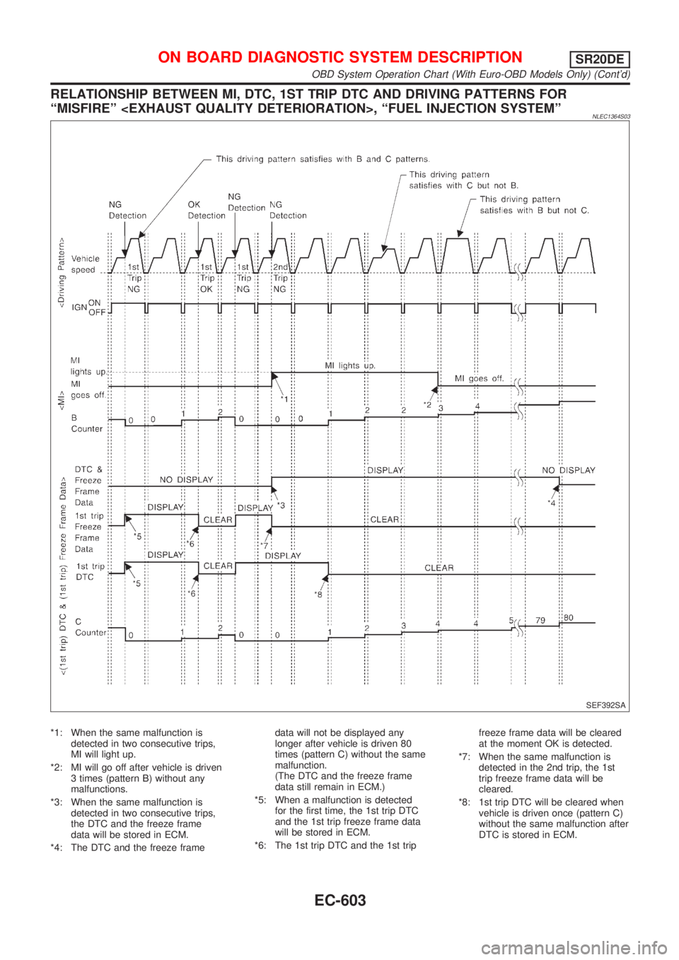
RELATIONSHIP BETWEEN MI, DTC, 1ST TRIP DTC AND DRIVING PATTERNS FOR
ªMISFIREº
NLEC1364S03
SEF392SA
*1: When the same malfunction is
detected in two consecutive trips,
MI will light up.
*2: MI will go off after vehicle is driven
3 times (pattern B) without any
malfunctions.
*3: When the same malfunction is
detected in two consecutive trips,
the DTC and the freeze frame
data will be stored in ECM.
*4: The DTC and the freeze framedata will not be displayed any
longer after vehicle is driven 80
times (pattern C) without the same
malfunction.
(The DTC and the freeze frame
data still remain in ECM.)
*5: When a malfunction is detected
for the first time, the 1st trip DTC
and the 1st trip freeze frame data
will be stored in ECM.
*6: The 1st trip DTC and the 1st tripfreeze frame data will be cleared
at the moment OK is detected.
*7: When the same malfunction is
detected in the 2nd trip, the 1st
trip freeze frame data will be
cleared.
*8: 1st trip DTC will be cleared when
vehicle is driven once (pattern C)
without the same malfunction after
DTC is stored in ECM.
ON BOARD DIAGNOSTIC SYSTEM DESCRIPTIONSR20DE
OBD System Operation Chart (With Euro-OBD Models Only) (Cont'd)
EC-603
Page 1030 of 3051
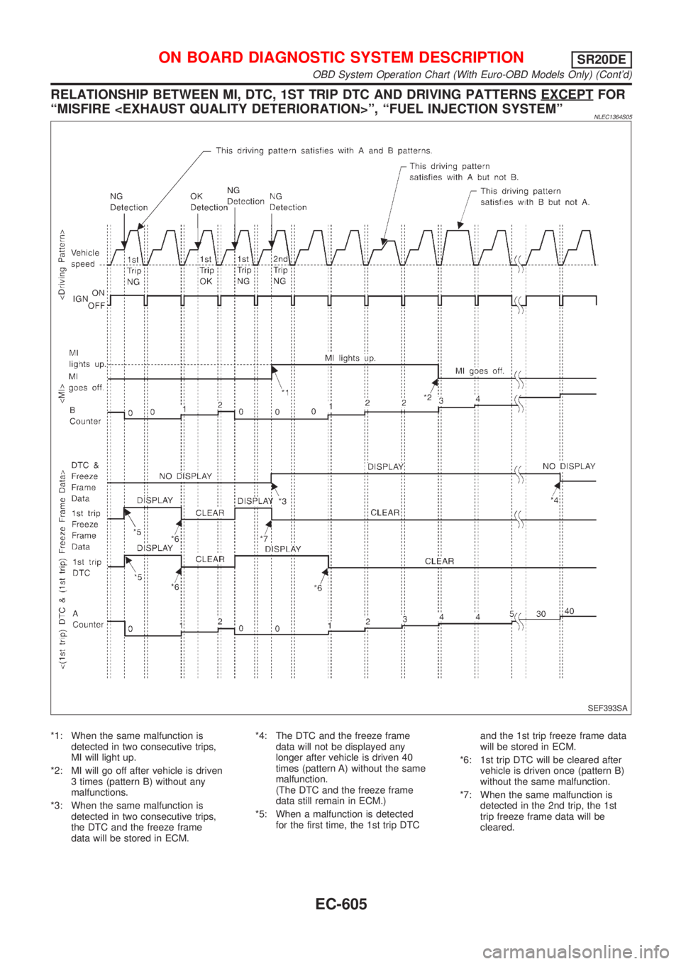
RELATIONSHIP BETWEEN MI, DTC, 1ST TRIP DTC AND DRIVING PATTERNS EXCEPTFOR
ªMISFIRE
NLEC1364S05
SEF393SA
*1: When the same malfunction is
detected in two consecutive trips,
MI will light up.
*2: MI will go off after vehicle is driven
3 times (pattern B) without any
malfunctions.
*3: When the same malfunction is
detected in two consecutive trips,
the DTC and the freeze frame
data will be stored in ECM.*4: The DTC and the freeze frame
data will not be displayed any
longer after vehicle is driven 40
times (pattern A) without the same
malfunction.
(The DTC and the freeze frame
data still remain in ECM.)
*5: When a malfunction is detected
for the first time, the 1st trip DTCand the 1st trip freeze frame data
will be stored in ECM.
*6: 1st trip DTC will be cleared after
vehicle is driven once (pattern B)
without the same malfunction.
*7: When the same malfunction is
detected in the 2nd trip, the 1st
trip freeze frame data will be
cleared.
ON BOARD DIAGNOSTIC SYSTEM DESCRIPTIONSR20DE
OBD System Operation Chart (With Euro-OBD Models Only) (Cont'd)
EC-605
Page 1055 of 3051
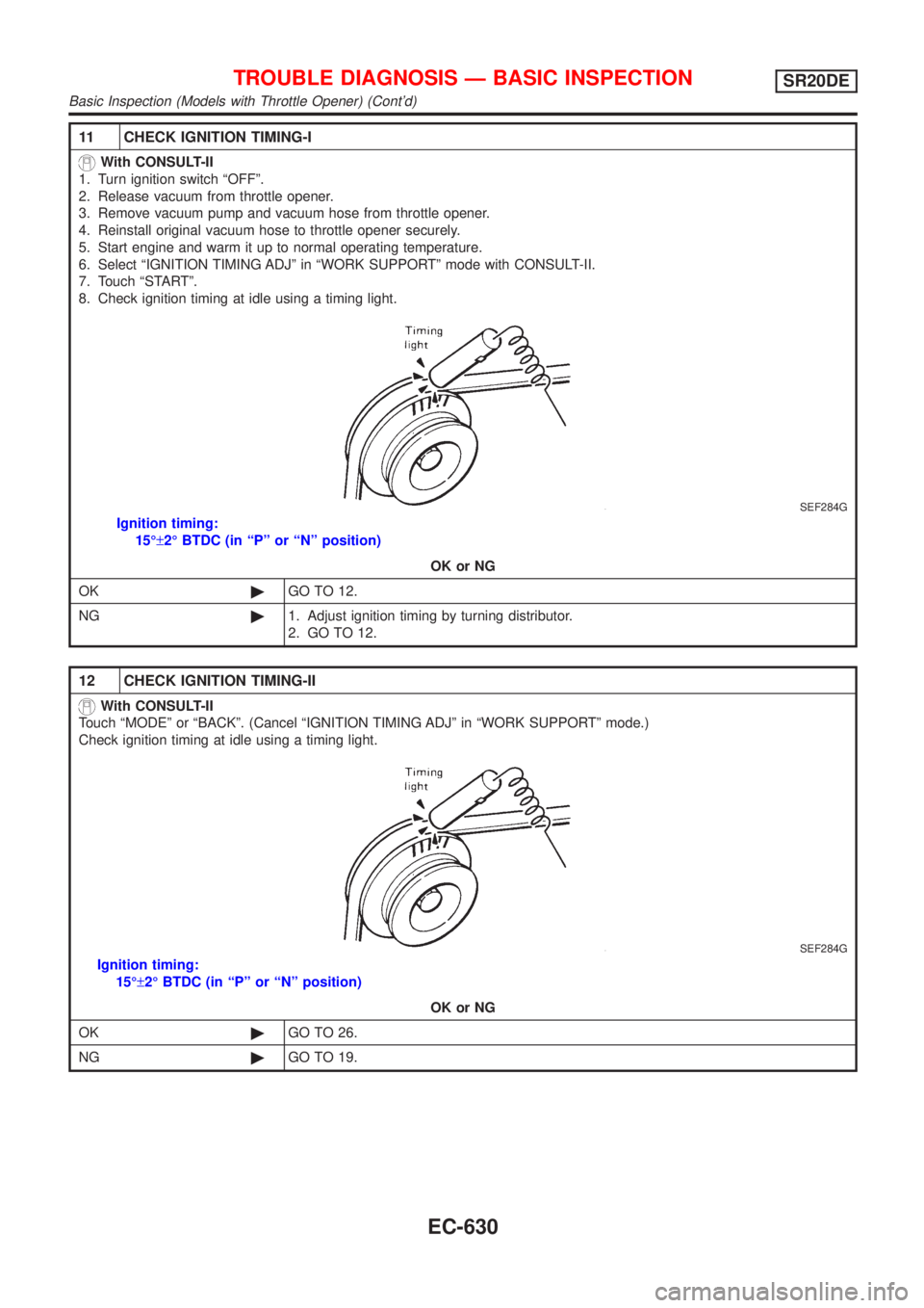
11 CHECK IGNITION TIMING-I
With CONSULT-II
1. Turn ignition switch ªOFFº.
2. Release vacuum from throttle opener.
3. Remove vacuum pump and vacuum hose from throttle opener.
4. Reinstall original vacuum hose to throttle opener securely.
5. Start engine and warm it up to normal operating temperature.
6. Select ªIGNITION TIMING ADJº in ªWORK SUPPORTº mode with CONSULT-II.
7. Touch ªSTARTº.
8. Check ignition timing at idle using a timing light.
SEF284G
Ignition timing:
15ɱ2É BTDC (in ªPº or ªNº position)
OK or NG
OK©GO TO 12.
NG©1. Adjust ignition timing by turning distributor.
2. GO TO 12.
12 CHECK IGNITION TIMING-II
With CONSULT-II
Touch ªMODEº or ªBACKº. (Cancel ªIGNITION TIMING ADJº in ªWORK SUPPORTº mode.)
Check ignition timing at idle using a timing light.
SEF284G
Ignition timing:
15ɱ2É BTDC (in ªPº or ªNº position)
OK or NG
OK©GO TO 26.
NG©GO TO 19.
TROUBLE DIAGNOSIS Ð BASIC INSPECTIONSR20DE
Basic Inspection (Models with Throttle Opener) (Cont'd)
EC-630
Page 1059 of 3051
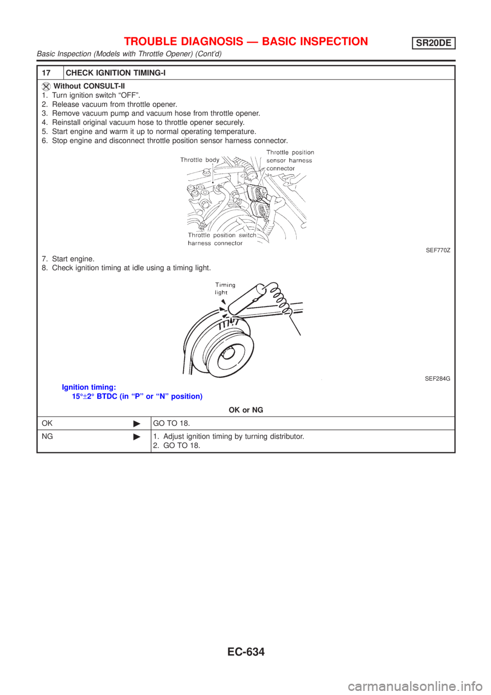
17 CHECK IGNITION TIMING-I
Without CONSULT-II
1. Turn ignition switch ªOFFº.
2. Release vacuum from throttle opener.
3. Remove vacuum pump and vacuum hose from throttle opener.
4. Reinstall original vacuum hose to throttle opener securely.
5. Start engine and warm it up to normal operating temperature.
6. Stop engine and disconnect throttle position sensor harness connector.
SEF770Z
7. Start engine.
8. Check ignition timing at idle using a timing light.
SEF284G
Ignition timing:
15ɱ2É BTDC (in ªPº or ªNº position)
OK or NG
OK©GO TO 18.
NG©1. Adjust ignition timing by turning distributor.
2. GO TO 18.
TROUBLE DIAGNOSIS Ð BASIC INSPECTIONSR20DE
Basic Inspection (Models with Throttle Opener) (Cont'd)
EC-634
Page 1082 of 3051
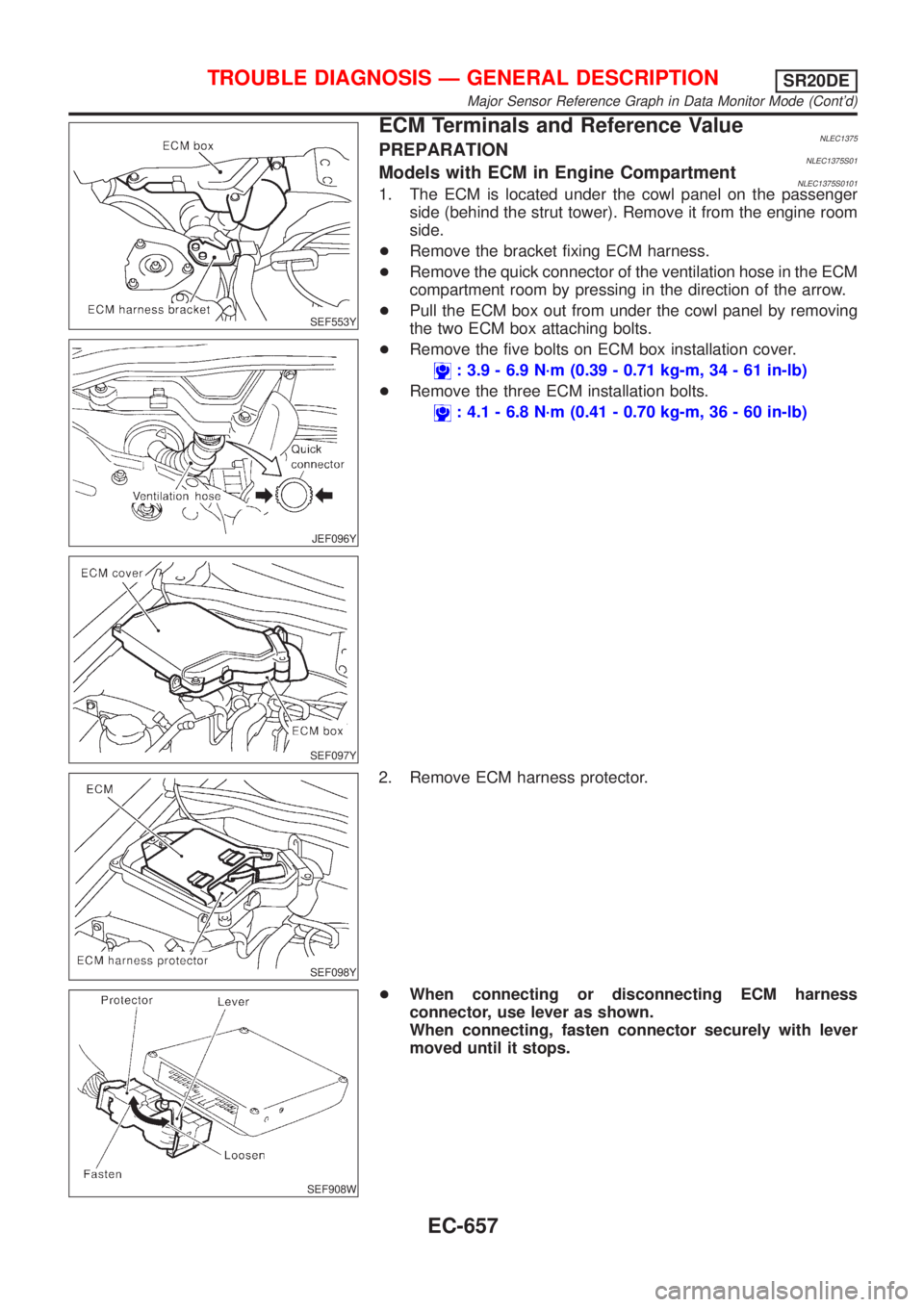
SEF553Y
JEF096Y
SEF097Y
ECM Terminals and Reference ValueNLEC1375PREPARATIONNLEC1375S01Models with ECM in Engine CompartmentNLEC1375S01011. The ECM is located under the cowl panel on the passenger
side (behind the strut tower). Remove it from the engine room
side.
+Remove the bracket fixing ECM harness.
+Remove the quick connector of the ventilation hose in the ECM
compartment room by pressing in the direction of the arrow.
+Pull the ECM box out from under the cowl panel by removing
the two ECM box attaching bolts.
+Remove the five bolts on ECM box installation cover.
: 3.9 - 6.9 N´m (0.39 - 0.71 kg-m, 34 - 61 in-lb)
+Remove the three ECM installation bolts.
: 4.1 - 6.8 N´m (0.41 - 0.70 kg-m, 36 - 60 in-lb)
SEF098Y
2. Remove ECM harness protector.
SEF908W
+When connecting or disconnecting ECM harness
connector, use lever as shown.
When connecting, fasten connector securely with lever
moved until it stops.
TROUBLE DIAGNOSIS Ð GENERAL DESCRIPTIONSR20DE
Major Sensor Reference Graph in Data Monitor Mode (Cont'd)
EC-657