Page 614 of 2898
ABS Actuator and Electric UnitNJBR0111S10
SBR630E
REMOVALNJBR0111S10011. Disconnect battery cable.
2. Drain brake fluid.
3. Remove mounting bracket fixing bolts and nuts.
4. Disconnect connector, brake pipes and remove fixing nuts.
INSTALLATIONNJBR0111S1002CAUTION:
After installation, refill brake fluid. Then bleed air.
1. Connect brake pipes temporarily.
2. Tighten fixing bolts and nuts.
3. Tighten brake pipes.
4. Connect connector and battery cable.
REMOVAL AND INSTALLATIONABS
ABS Actuator and Electric Unit
BR-98
Page 616 of 2898
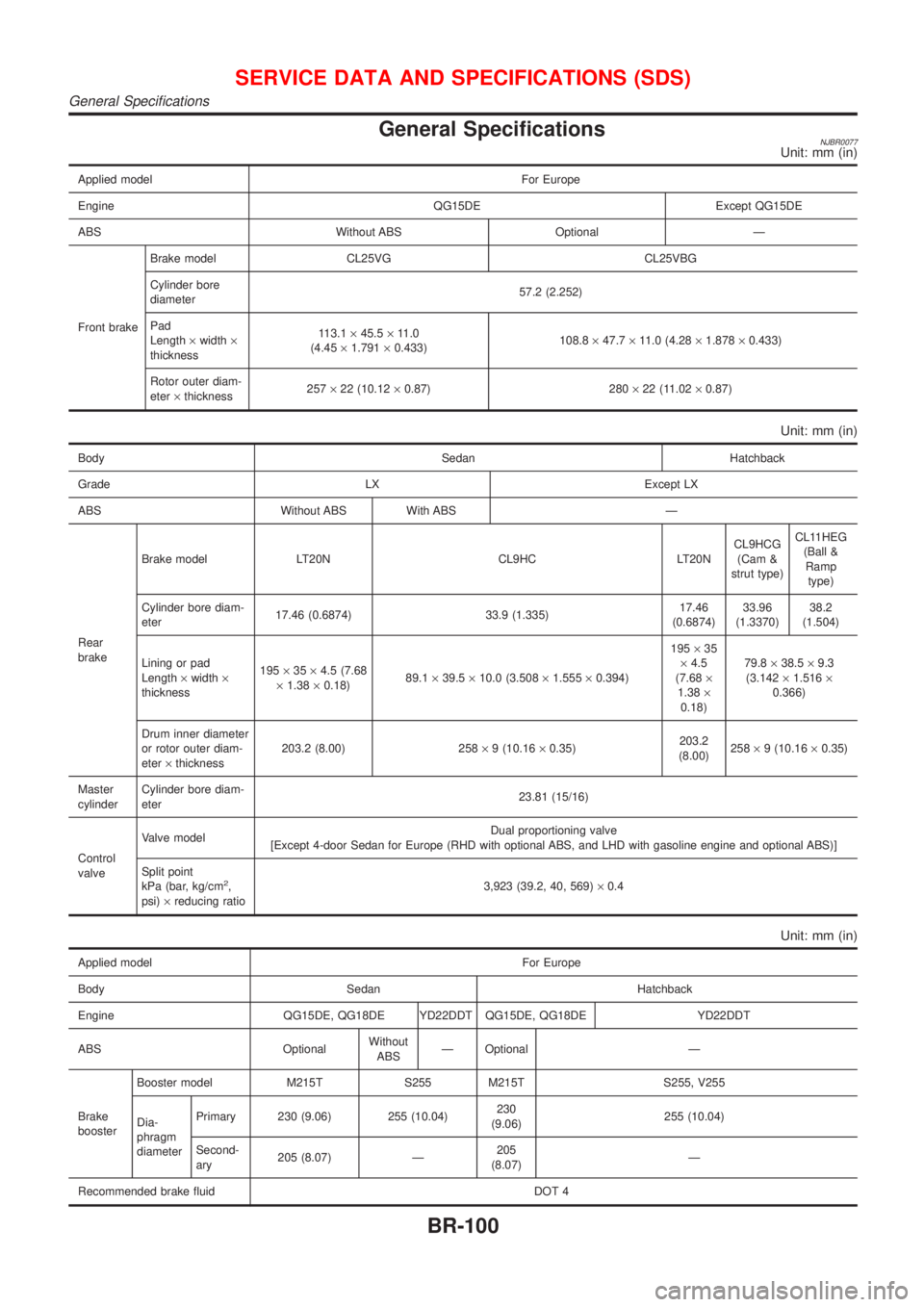
General SpecificationsNJBR0077Unit: mm (in)
Applied model For Europe
Engine QG15DE Except QG15DE
ABS Without ABS Optional Ð
Front brakeBrake model CL25VG CL25VBG
Cylinder bore
diameter57.2 (2.252)
Pad
Length´width´
thickness113.1´45.5´11.0
(4.45´1.791´0.433)108.8´47.7´11.0 (4.28´1.878´0.433)
Rotor outer diam-
eter´thickness257´22 (10.12´0.87) 280´22 (11.02´0.87)
Unit: mm (in)
Body Sedan Hatchback
Grade LX Except LX
ABS Without ABS With ABS Ð
Rear
brakeBrake model LT20N CL9HC LT20NCL9HCG
(Cam &
strut type)CL11HEG
(Ball &
Ramp
type)
Cylinder bore diam-
eter17.46 (0.6874) 33.9 (1.335)17.46
(0.6874)33.96
(1.3370)38.2
(1.504)
Lining or pad
Length´width´
thickness195´35´4.5 (7.68
´1.38´0.18)89.1´39.5´10.0 (3.508´1.555´0.394)195´35
´4.5
(7.68´
1.38´
0.18)79.8´38.5´9.3
(3.142´1.516´
0.366)
Drum inner diameter
or rotor outer diam-
eter´thickness203.2 (8.00) 258´9 (10.16´0.35)203.2
(8.00)258´9 (10.16´0.35)
Master
cylinderCylinder bore diam-
eter23.81 (15/16)
Control
valveValve modelDual proportioning valve
[Except 4-door Sedan for Europe (RHD with optional ABS, and LHD with gasoline engine and optional ABS)]
Split point
kPa (bar, kg/cm
2,
psi)´reducing ratio3,923 (39.2, 40, 569)´0.4
Unit: mm (in)
Applied model For Europe
Body Sedan Hatchback
Engine QG15DE, QG18DE YD22DDT QG15DE, QG18DE YD22DDT
ABS OptionalWithout
ABSÐ Optional Ð
Brake
boosterBooster model M215T S255 M215T S255, V255
Dia-
phragm
diameterPrimary 230 (9.06) 255 (10.04)230
(9.06)255 (10.04)
Second-
ary205 (8.07) Ð205
(8.07)Ð
Recommended brake fluid DOT 4
SERVICE DATA AND SPECIFICATIONS (SDS)
General Specifications
BR-100
Page 702 of 2898
SBR820BA
PrecautionsNJCL0001+Recommended fluid is brake fluid ªDOT 4º. Refer to
MA-16, ªFluid and Lubricantsº.
+Never reuse drained brake fluid.
+Be careful not to splash brake fluid on painted areas.
+When removing and installing clutch piping, use Tool.
+Use new brake fluid to clean or wash all parts of master
cylinder and operating cylinder.
+Never use mineral oils such as gasoline or kerosene. It will
ruin the rubber parts of the hydraulic system.
WARNING:
After cleaning clutch disc, wipe it with a dust collector. Do not
use compressed air.
PRECAUTIONS
Precautions
CL-2
Page 710 of 2898
CLUTCH PEDAL ADJUSTMENTNJCL0006S04Pedal StrokeNJCL0006S04011. Loosen the pedal stopper bolt completely (so there is no con-
tact between pedal and stopper bolt).
2. Adjust pedal stroke to the specified value with the master cyl-
inder push rod.
3. Adjust the pedal stopper bolt until it is just in contact with the
pedal, then tighten the lock nut.
4. Once stroke is set to specification, adjust clutch pedal free
play.
Pedal stroke ªSº.
Refer to ªSDSº, CL-24.
Pedal Free PlayNJCL0006S04021. Adjust pedal free play to the specified value with the master
cylinder push rod.
2. Tighten lock nut of the master cylinder push rod.
+Push on the clutch pedal until resistance is felt, and check the
distance the pedal moves.
Pedal free play ªAº.
Refer to ªSDSº, CL-24.
SCL838
SCL839
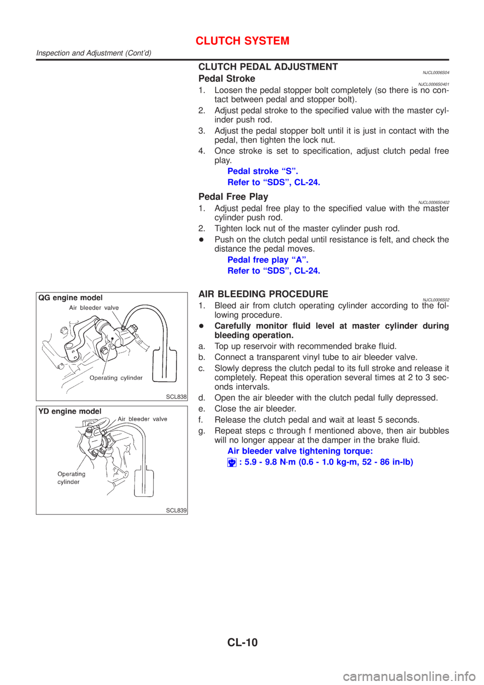
AIR BLEEDING PROCEDURENJCL0006S021. Bleed air from clutch operating cylinder according to the fol-
lowing procedure.
+Carefully monitor fluid level at master cylinder during
bleeding operation.
a. Top up reservoir with recommended brake fluid.
b. Connect a transparent vinyl tube to air bleeder valve.
c. Slowly depress the clutch pedal to its full stroke and release it
completely. Repeat this operation several times at 2 to 3 sec-
onds intervals.
d. Open the air bleeder with the clutch pedal fully depressed.
e. Close the air bleeder.
f. Release the clutch pedal and wait at least 5 seconds.
g. Repeat steps c through f mentioned above, then air bubbles
will no longer appear at the damper in the brake fluid.
Air bleeder valve tightening torque:
: 5.9 - 9.8 N´m (0.6 - 1.0 kg-m, 52 - 86 in-lb)
CLUTCH SYSTEM
Inspection and Adjustment (Cont'd)
CL-10
Page 712 of 2898
RemovalNJCL00081. Drain brake fluid.
CAUTION:
Be careful not to splash brake fluid on painted areas; it may
cause paint damage. If brake fluid is splashed on painted
areas, wash it away with water immediately.
2. Remove clutch tube using a flare nut wrench.
3. Remove snap pin between clutch pedal and push rod, and
remove clevis pin.
4. Unscrew master cylinder assembly mounting nuts and remove
master cylinder assembly from vehicle.
InstallationNJCL00091. Connect clutch tube to master cylinder assembly, and hand-
tighten flare nut.
2. Install master cylinder assembly to vehicle, and tighten mount-
ing nuts to the specified torque.
: 11 - 14 N´m (1.1 - 1.5 kg-m,8-10ft-lb)
3. Tighten clutch tube flare nut using a flare nut torque wrench.
: 15 - 18 N´m (1.5 - 1.8 kg-m, 11 - 13 ft-lb)
4. After installing clevis pin, install snap pin to connect clutch
pedal to push rod.
5. After finishing the operation, bleed air from clutch piping con-
nector and operating cylinder. (Refer to ªAir Bleeding
Procedureº, CL-10.)
SCL725
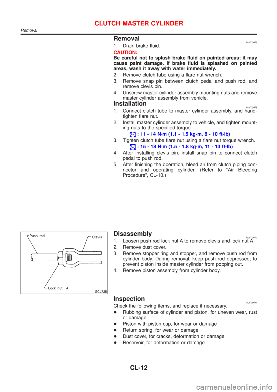
DisassemblyNJCL00101. Loosen push rod lock nut A to remove clevis and lock nut A.
2. Remove dust cover.
3. Remove stopper ring and stopper, and remove push rod from
cylinder body. During removal, keep push rod depressed, to
prevent piston inside master cylinder from popping out.
4. Remove piston assembly from cylinder body.
InspectionNJCL0011Check the following items, and replace if necessary.
+Rubbing surface of cylinder and piston, for uneven wear, rust
or damage
+Piston with piston cup, for wear or damage
+Return spring, for wear or damage
+Dust cover, for cracks, deformation or damage
+Reservoir, for deformation or damage
CLUTCH MASTER CYLINDER
Removal
CL-12
Page 714 of 2898
ComponentsNJCL0019
YCL003
RemovalNJCL00201. Drain brake fluid.
CAUTION:
Be careful not to splash brake fluid on painted areas; it may
cause paint damage. If brake fluid is splashed on painted
areas, wash it away with water immediately.
2. Remove union bolt and clutch hose from operating cylinder.
3. Remove operating cylinder mounting bolts, and remove cylin-
der from vehicle.
DisassemblyNJCL0021Remove dust cover, and remove piston assembly from cylinder
body.
InspectionNJCL0022Inspect for following, and replace parts if necessary.
+Damage, foreign material, wear, rust, and pinholes on the cyl-
inder inner surface, piston, and sliding part of piston cup
+Weak spring
+Crack and deformation of dust cover
OPERATING CYLINDER
Components
CL-14
Page 716 of 2898
SCL729
RemovalNJCL00421. Remove fuel filter mounting bracket.
2. Remove air cleaner and air duct.
3. Drain brake fluid.
CAUTION:
Be careful not to splash brake fluid on painted areas; it may
cause paint damage. If brake fluid is splashed on painted
areas, wash it away with water immediately.
4. Remove flare nut using a flare nut wrench.
5. Remove clutch hose and clutch tube.
SCL730
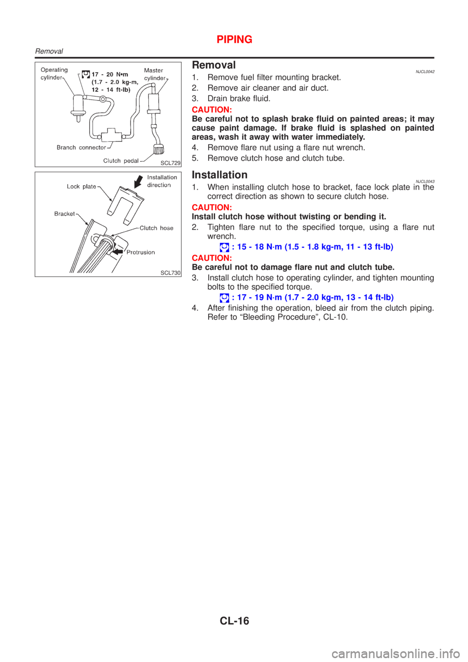
InstallationNJCL00431. When installing clutch hose to bracket, face lock plate in the
correct direction as shown to secure clutch hose.
CAUTION:
Install clutch hose without twisting or bending it.
2. Tighten flare nut to the specified torque, using a flare nut
wrench.
: 15 - 18 N´m (1.5 - 1.8 kg-m, 11 - 13 ft-lb)
CAUTION:
Be careful not to damage flare nut and clutch tube.
3. Install clutch hose to operating cylinder, and tighten mounting
bolts to the specified torque.
: 17 - 19 N´m (1.7 - 2.0 kg-m, 13 - 14 ft-lb)
4. After finishing the operation, bleed air from the clutch piping.
Refer to ªBleeding Procedureº, CL-10.
PIPING
Removal
CL-16
Page 2133 of 2898
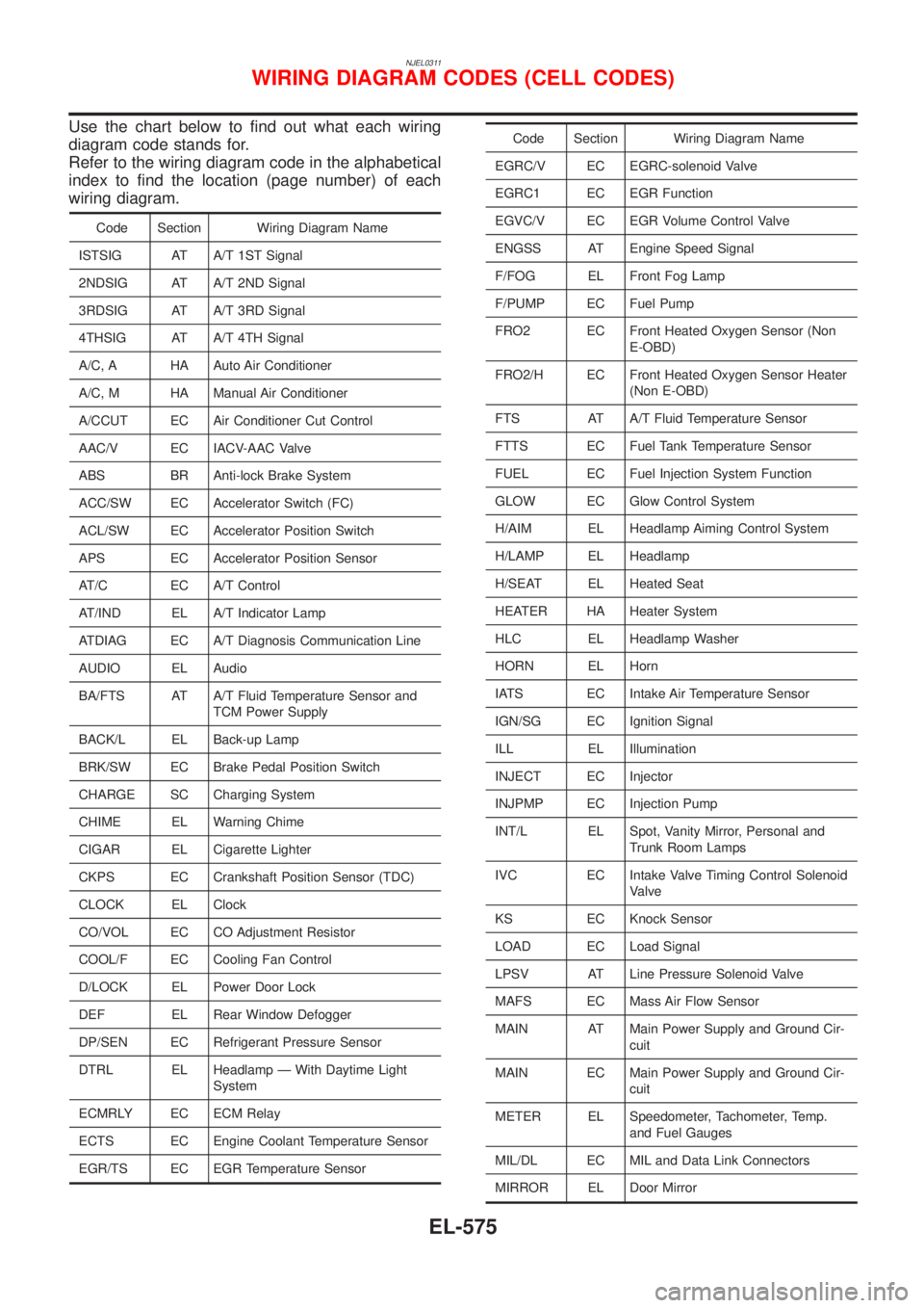
NJEL0311
Use the chart below to find out what each wiring
diagram code stands for.
Refer to the wiring diagram code in the alphabetical
index to find the location (page number) of each
wiring diagram.
Code Section Wiring Diagram Name
ISTSIG AT A/T 1ST Signal
2NDSIG AT A/T 2ND Signal
3RDSIG AT A/T 3RD Signal
4THSIG AT A/T 4TH Signal
A/C, A HA Auto Air Conditioner
A/C, M HA Manual Air Conditioner
A/CCUT EC Air Conditioner Cut Control
AAC/V EC IACV-AAC Valve
ABS BR Anti-lock Brake System
ACC/SW EC Accelerator Switch (FC)
ACL/SW EC Accelerator Position Switch
APS EC Accelerator Position Sensor
AT/C EC A/T Control
AT/IND EL A/T Indicator Lamp
ATDIAG EC A/T Diagnosis Communication Line
AUDIO EL Audio
BA/FTS AT A/T Fluid Temperature Sensor and
TCM Power Supply
BACK/L EL Back-up Lamp
BRK/SW EC Brake Pedal Position Switch
CHARGE SC Charging System
CHIME EL Warning Chime
CIGAR EL Cigarette Lighter
CKPS EC Crankshaft Position Sensor (TDC)
CLOCK EL Clock
CO/VOL EC CO Adjustment Resistor
COOL/F EC Cooling Fan Control
D/LOCK EL Power Door Lock
DEF EL Rear Window Defogger
DP/SEN EC Refrigerant Pressure Sensor
DTRL EL Headlamp Ð With Daytime Light
System
ECMRLY EC ECM Relay
ECTS EC Engine Coolant Temperature Sensor
EGR/TS EC EGR Temperature Sensor
Code Section Wiring Diagram Name
EGRC/V EC EGRC-solenoid Valve
EGRC1 EC EGR Function
EGVC/V EC EGR Volume Control Valve
ENGSS AT Engine Speed Signal
F/FOG EL Front Fog Lamp
F/PUMP EC Fuel Pump
FRO2 EC Front Heated Oxygen Sensor (Non
E-OBD)
FRO2/H EC Front Heated Oxygen Sensor Heater
(Non E-OBD)
FTS AT A/T Fluid Temperature Sensor
FTTS EC Fuel Tank Temperature Sensor
FUEL EC Fuel Injection System Function
GLOW EC Glow Control System
H/AIM EL Headlamp Aiming Control System
H/LAMP EL Headlamp
H/SEAT EL Heated Seat
HEATER HA Heater System
HLC EL Headlamp Washer
HORN EL Horn
IATS EC Intake Air Temperature Sensor
IGN/SG EC Ignition Signal
ILL EL Illumination
INJECT EC Injector
INJPMP EC Injection Pump
INT/L EL Spot, Vanity Mirror, Personal and
Trunk Room Lamps
IVC EC Intake Valve Timing Control Solenoid
Valve
KS EC Knock Sensor
LOAD EC Load Signal
LPSV AT Line Pressure Solenoid Valve
MAFS EC Mass Air Flow Sensor
MAIN AT Main Power Supply and Ground Cir-
cuit
MAIN EC Main Power Supply and Ground Cir-
cuit
METER EL Speedometer, Tachometer, Temp.
and Fuel Gauges
MIL/DL EC MIL and Data Link Connectors
MIRROR EL Door Mirror
WIRING DIAGRAM CODES (CELL CODES)
EL-575