2001 NISSAN ALMERA brake fluid
[x] Cancel search: brake fluidPage 120 of 2898
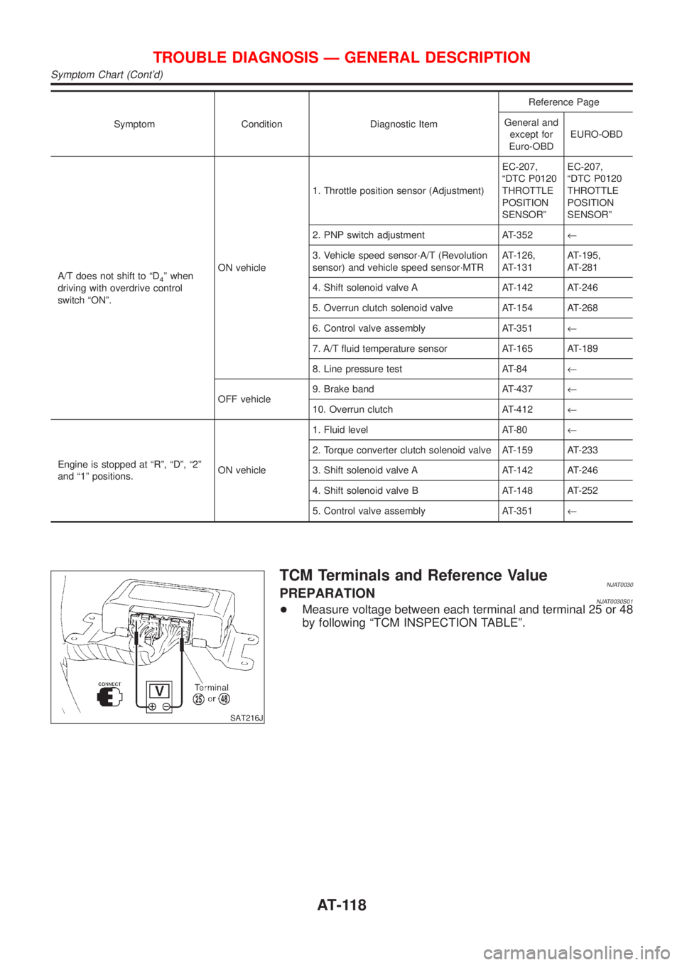
Symptom Condition Diagnostic ItemReference Page
General and
except for
Euro-OBDEURO-OBD
A/T does not shift to ªD
4º when
driving with overdrive control
switch ªONº.ON vehicle1. Throttle position sensor (Adjustment)EC-207,
ªDTC P0120
THROTTLE
POSITION
SENSORºEC-207,
ªDTC P0120
THROTTLE
POSITION
SENSORº
2. PNP switch adjustment AT-352¬
3. Vehicle speed sensor´A/T (Revolution
sensor) and vehicle speed sensor´MTRAT-126,
AT-131AT-195,
AT-281
4. Shift solenoid valve A AT-142 AT-246
5. Overrun clutch solenoid valve AT-154 AT-268
6. Control valve assembly AT-351¬
7. A/T fluid temperature sensor AT-165 AT-189
8. Line pressure test AT-84¬
OFF vehicle9. Brake band AT-437¬
10. Overrun clutch AT-412¬
Engine is stopped at ªRº, ªDº, ª2º
and ª1º positions.ON vehicle1. Fluid level AT-80¬
2. Torque converter clutch solenoid valve AT-159 AT-233
3. Shift solenoid valve A AT-142 AT-246
4. Shift solenoid valve B AT-148 AT-252
5. Control valve assembly AT-351¬
SAT216J
TCM Terminals and Reference ValueNJAT0030PREPARATIONNJAT0030S01+Measure voltage between each terminal and terminal 25 or 48
by following ªTCM INSPECTION TABLEº.
TROUBLE DIAGNOSIS Ð GENERAL DESCRIPTION
Symptom Chart (Cont'd)
AT-118
Page 124 of 2898
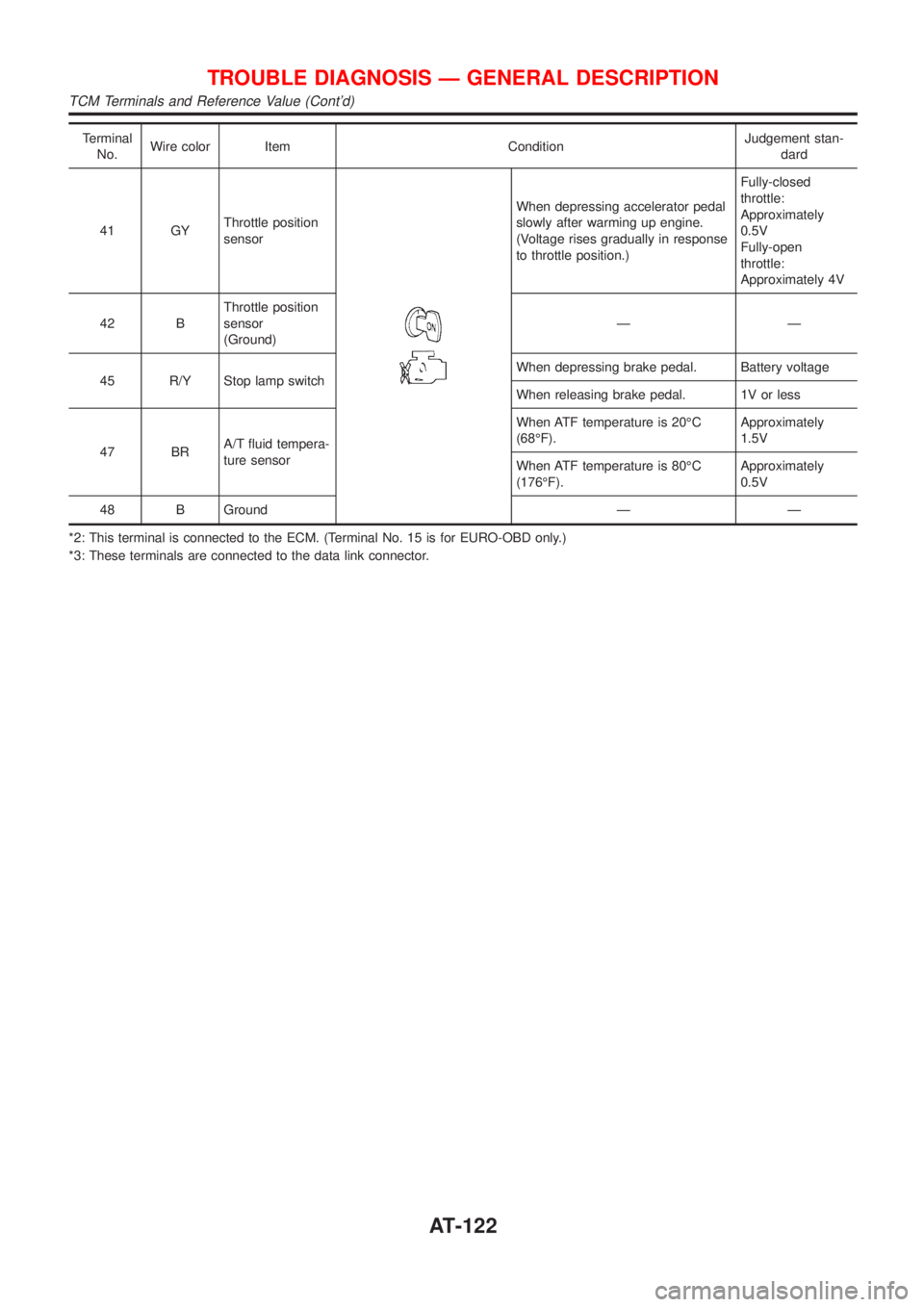
Terminal
No.Wire color Item ConditionJudgement stan-
dard
41 GYThrottle position
sensor
When depressing accelerator pedal
slowly after warming up engine.
(Voltage rises gradually in response
to throttle position.)Fully-closed
throttle:
Approximately
0.5V
Fully-open
throttle:
Approximately 4V
42 BThrottle position
sensor
(Ground)ÐÐ
45 R/Y Stop lamp switchWhen depressing brake pedal. Battery voltage
When releasing brake pedal. 1V or less
47 BRA/T fluid tempera-
ture sensorWhen ATF temperature is 20ÉC
(68ÉF).Approximately
1.5V
When ATF temperature is 80ÉC
(176ÉF).Approximately
0.5V
48 B Ground Ð Ð
*2: This terminal is connected to the ECM. (Terminal No. 15 is for EURO-OBD only.)
*3: These terminals are connected to the data link connector.
TROUBLE DIAGNOSIS Ð GENERAL DESCRIPTION
TCM Terminals and Reference Value (Cont'd)
AT-122
Page 307 of 2898
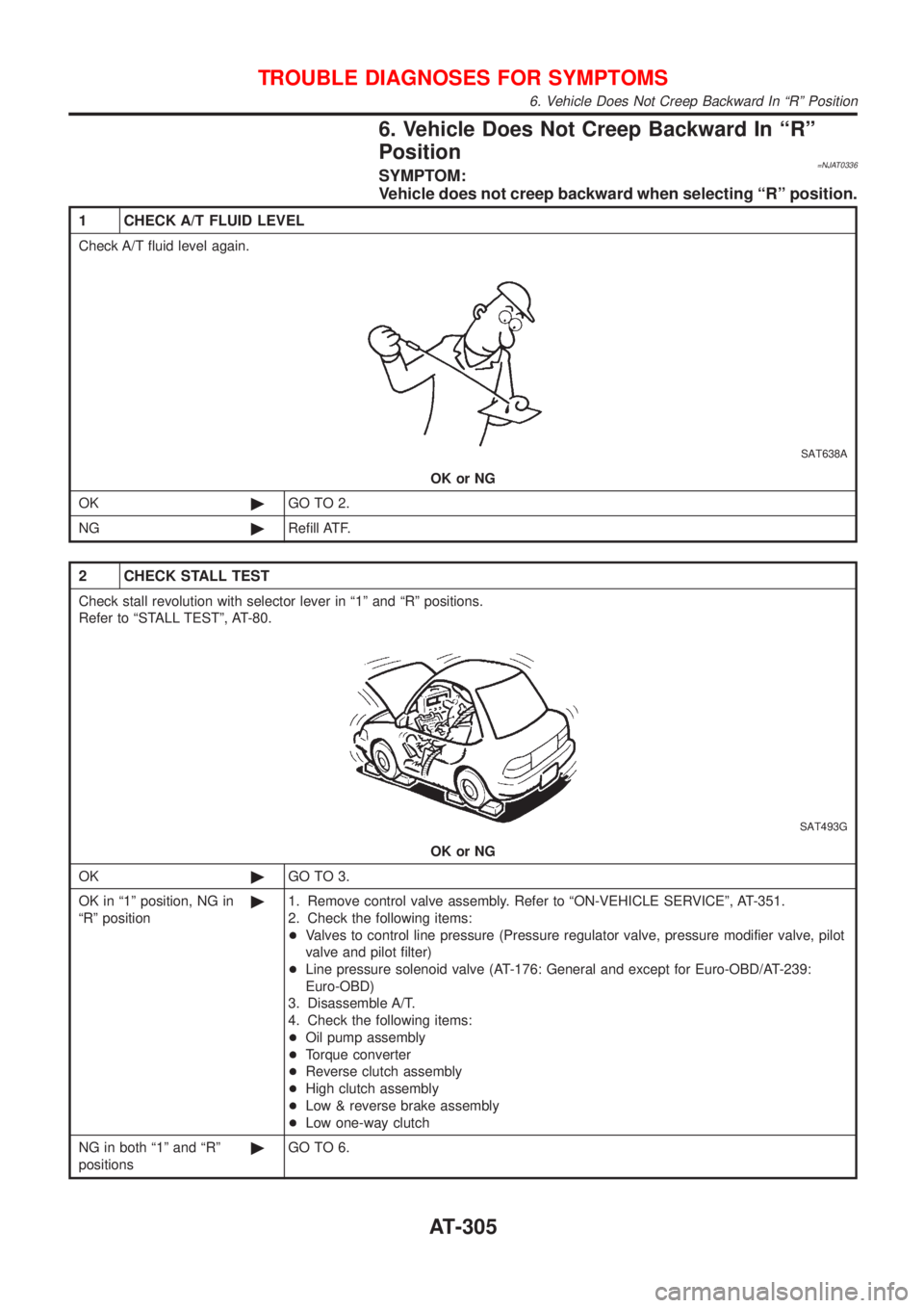
6. Vehicle Does Not Creep Backward In ªRº
Position
=NJAT0336SYMPTOM:
Vehicle does not creep backward when selecting ªRº position.
1 CHECK A/T FLUID LEVEL
Check A/T fluid level again.
SAT638A
OK or NG
OK©GO TO 2.
NG©Refill ATF.
2 CHECK STALL TEST
Check stall revolution with selector lever in ª1º and ªRº positions.
Refer to ªSTALL TESTº, AT-80.
SAT493G
OK or NG
OK©GO TO 3.
OK in ª1º position, NG in
ªRº position©1. Remove control valve assembly. Refer to ªON-VEHICLE SERVICEº, AT-351.
2. Check the following items:
+Valves to control line pressure (Pressure regulator valve, pressure modifier valve, pilot
valve and pilot filter)
+Line pressure solenoid valve (AT-176: General and except for Euro-OBD/AT-239:
Euro-OBD)
3. Disassemble A/T.
4. Check the following items:
+Oil pump assembly
+Torque converter
+Reverse clutch assembly
+High clutch assembly
+Low & reverse brake assembly
+Low one-way clutch
NG in both ª1º and ªRº
positions©GO TO 6.
TROUBLE DIAGNOSES FOR SYMPTOMS
6. Vehicle Does Not Creep Backward In ªRº Position
AT-305
Page 358 of 2898
SAT058K
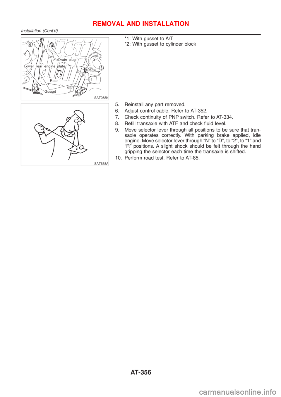
*1: With gusset to A/T
*2: With gusset to cylinder block
SAT638A
5. Reinstall any part removed.
6. Adjust control cable. Refer to AT-352.
7. Check continuity of PNP switch. Refer to AT-334.
8. Refill transaxle with ATF and check fluid level.
9. Move selector lever through all positions to be sure that tran-
saxle operates correctly. With parking brake applied, idle
engine. Move selector lever through ªNº to ªDº, to ª2º, to ª1º and
ªRº positions. A slight shock should be felt through the hand
gripping the selector each time the transaxle is shifted.
10. Perform road test. Refer to AT-85.
REMOVAL AND INSTALLATION
Installation (Cont'd)
AT-356
Page 421 of 2898
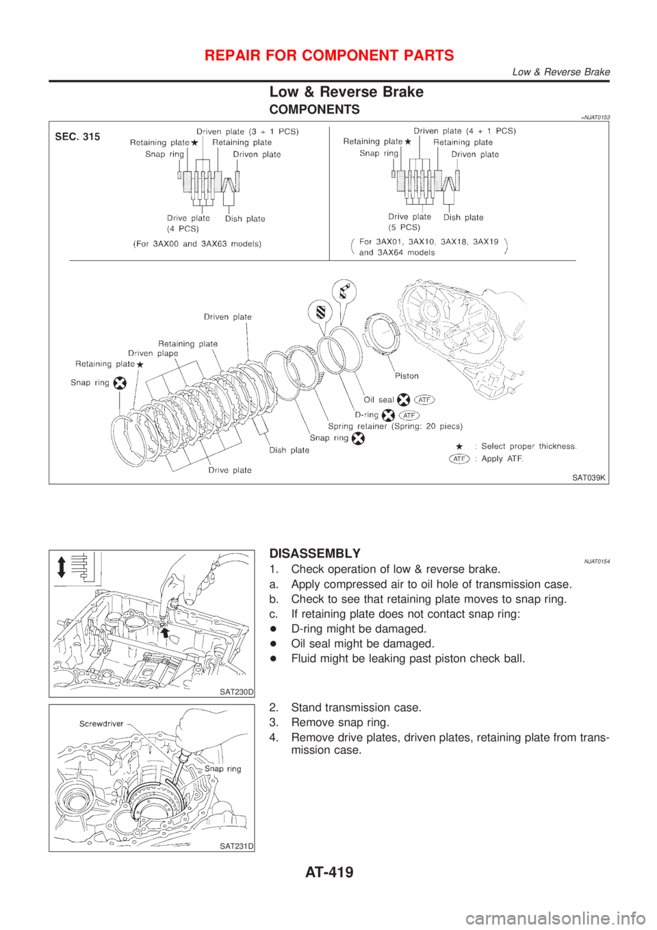
Low & Reverse Brake
COMPONENTS=NJAT0153
SAT039K
SAT230D
DISASSEMBLYNJAT01541. Check operation of low & reverse brake.
a. Apply compressed air to oil hole of transmission case.
b. Check to see that retaining plate moves to snap ring.
c. If retaining plate does not contact snap ring:
+D-ring might be damaged.
+Oil seal might be damaged.
+Fluid might be leaking past piston check ball.
SAT231D
2. Stand transmission case.
3. Remove snap ring.
4. Remove drive plates, driven plates, retaining plate from trans-
mission case.
REPAIR FOR COMPONENT PARTS
Low & Reverse Brake
AT-419
Page 517 of 2898
BRAKE SYSTEM
SECTION
BR
CONTENTS
PRECAUTIONS...............................................................4
Supplemental Restraint System (SRS)²AIR
BAG²and²SEAT BELT PRE-TENSIONER²...............4
Precautions for Brake System .....................................4
Precautions When Working On ABS ...........................5
Wiring Diagrams and Trouble Diagnosis .....................5
PREPARATION...............................................................6
Commercial Service Tools ...........................................6
NOISE, VIBRATION AND HARSHNESS (NVH)
TROUBLESHOOTING.....................................................7
NVH Troubleshooting Chart.........................................7
ON-VEHICLE SERVICE..................................................8
Checking Brake Fluid Level.........................................8
Checking Brake Line ...................................................8
Changing Brake Fluid ..................................................8
Brake Burnishing Procedure........................................8
Bleeding Brake System ...............................................9
BRAKE HYDRAULIC LINE...........................................10
Hydraulic Circuit.........................................................10
Removal .....................................................................10
Inspection................................................................... 11
Installation .................................................................. 11
BRAKE PEDAL AND BRACKET..................................12
Removal and Installation ...........................................12
Inspection...................................................................12
Adjustment .................................................................12
MASTER CYLINDER (TOKICO)...................................14
Removal .....................................................................14
Disassembly...............................................................15
Inspection...................................................................15
Assembly ...................................................................15
Installation ..................................................................16
MASTER CYLINDER [BOSCH (NABCO)]...................17
Removal .....................................................................17
Disassembly...............................................................17
Inspection...................................................................18
Assembly ...................................................................18
Installation ..................................................................19BRAKE BOOSTER........................................................20
On-vehicle Service.....................................................20
OPERATING CHECK...............................................20
AIRTIGHT CHECK...................................................20
Removal .....................................................................20
Inspection...................................................................20
OUTPUT ROD LENGTH CHECK..............................20
Installation ..................................................................21
VACUUM HOSE.............................................................22
Removal and Installation ...........................................22
Inspection...................................................................22
HOSES AND CONNECTORS...................................22
CHECK VALVE........................................................22
VACUUM PUMP............................................................23
Removal .....................................................................23
Installation ..................................................................24
Inspection...................................................................24
Component ................................................................25
Disassembly...............................................................25
Assembly ...................................................................25
FRONT DISC BRAKE...................................................27
Component ................................................................27
Pad Replacement ......................................................27
Removal .....................................................................28
Disassembly...............................................................28
Inspection...................................................................28
CALIPER.................................................................28
ROTOR...................................................................29
Assembly ...................................................................30
Installation ..................................................................30
REAR DRUM BRAKE...................................................31
Components...............................................................31
Removal .....................................................................31
Inspection - Wheel Cylinder ......................................32
Wheel Cylinder Overhaul...........................................33
Inspection - Drum ......................................................33
Inspection - Lining .....................................................33
Installation ..................................................................33
Page 520 of 2898

Supplemental Restraint System (SRS) ªAIR
BAGº and ªSEAT BELT PRE-TENSIONERº
NJBR0139The Supplemental Restraint System such as ªAIR BAGº and ªSEAT BELT PRE-TENSIONERº used along with
a seat belt, helps to reduce the risk or severity of injury to the driver and front passenger for certain types of
collision. The SRS system composition which is available to NISSAN MODEL N16 is as follows (The compo-
sition varies according to the destination and optional equipment.):
+For a frontal collision
The Supplemental Restraint System consists of driver air bag module (located in the center of the steer-
ing wheel), front passenger air bag module (located on the instrument panel on passenger side), front seat
belt pre-tensioners, a diagnosis sensor unit, warning lamp, wiring harness and spiral cable.
+For a side collision
The Supplemental Restraint System consists of front side air bag module (located in the outer side of front
seat), side air bag (satellite) sensor, diagnosis sensor unit (one of components of air bags for a frontal
collision), wiring harness, warning lamp (one of components of air bags for a frontal collision).
Information necessary to service the system safely is included in theRS sectionof this Service Manual.
WARNING:
+To avoid rendering the SRS inoperative, which could increase the risk of personal injury or death
in the event of a collision which would result in air bag inflation, all maintenance should be per-
formed by an authorized NISSAN dealer.
+Improper maintenance, including incorrect removal and installation of the SRS, can lead to per-
sonal injury caused by unintentional activation of the system. For removal of Spiral Cable and Air
Bag Module, see the RS section.
+Do not use electrical test equipment on any circuit related to the SRS unless instructed to in this
Service Manual. SRS wiring harnesses can be identified by yellow harness connector.
SBR686C
Precautions for Brake SystemNJBR0002+Recommended fluid is brake fluid ªDOT 4º.
+Never reuse drained brake fluid.
+Be careful not to splash brake fluid on painted areas.
+To clean or wash all parts of master cylinder, disc brake
caliper and wheel cylinder, use clean brake fluid.
+Never use mineral oils such as gasoline or kerosene. They
will ruin rubber parts of the hydraulic system.
+Use flare nut wrench when removing and installing brake
tube.
+Always torque brake lines when installing.
+Burnish the brake contact surfaces after refinishing or
replacing drums or rotors, after replacing pads or linings,
or if a soft pedal occurs at very low mileage.
Refer to ªBrake Burnishing Procedureº, ªON-VEHICLE
SERVICEº, BR-8.
WARNING:
+Clean brake pads and shoes with a waste cloth, then wipe
with a dust collector.
PRECAUTIONS
Supplemental Restraint System (SRS) ªAIR BAGº and ªSEAT BELT PRE-TENSIONERº
BR-4
Page 522 of 2898
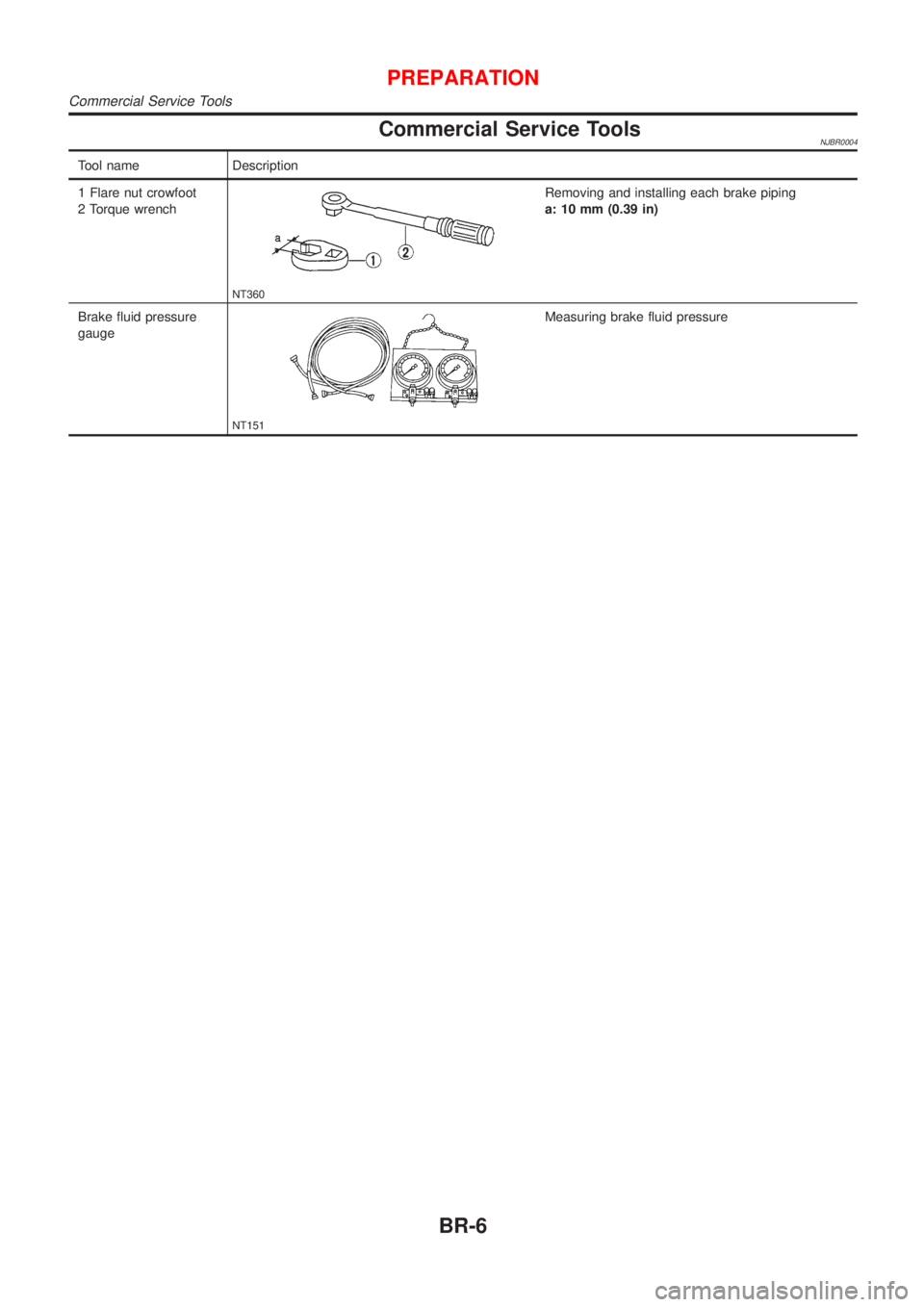
Commercial Service ToolsNJBR0004
Tool name Description
1 Flare nut crowfoot
2 Torque wrench
NT360
Removing and installing each brake piping
a: 10 mm (0.39 in)
Brake fluid pressure
gauge
NT151
Measuring brake fluid pressure
PREPARATION
Commercial Service Tools
BR-6