2001 NISSAN ALMERA heater
[x] Cancel search: heaterPage 1342 of 2898
SEF434Z
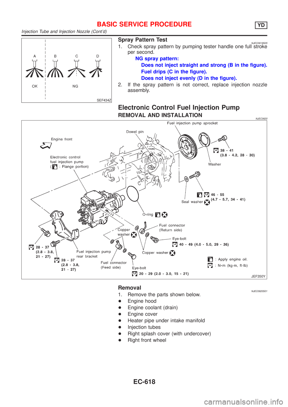
Spray Pattern TestNJEC0619S051. Check spray pattern by pumping tester handle one full stroke
per second.
NG spray pattern:
Does not inject straight and strong (B in the figure).
Fuel drips (C in the figure).
Does not inject evenly (D in the figure).
2. If the spray pattern is not correct, replace injection nozzle
assembly.
Electronic Control Fuel Injection Pump
REMOVAL AND INSTALLATIONNJEC0620
JEF350Y
RemovalNJEC0620S011. Remove the parts shown below.
+Engine hood
+Engine coolant (drain)
+Engine cover
+Heater pipe under intake manifold
+Injection tubes
+Right splash cover (with undercover)
+Right front wheel
BASIC SERVICE PROCEDUREYD
Injection Tube and Injection Nozzle (Cont'd)
EC-618
Page 1975 of 2898
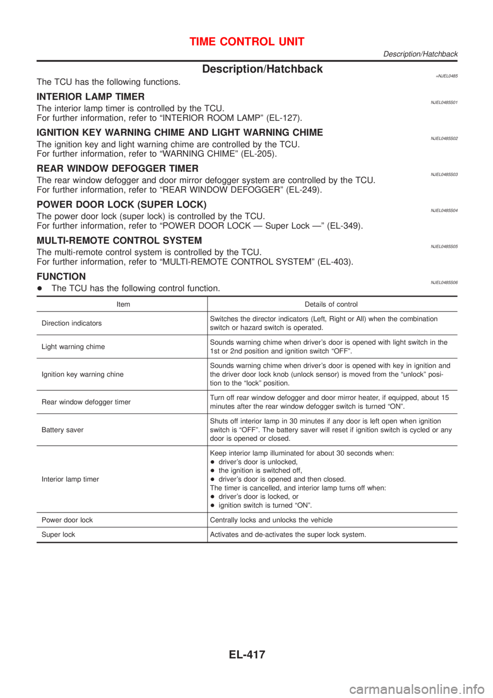
Description/Hatchback=NJEL0485The TCU has the following functions.
INTERIOR LAMP TIMERNJEL0485S01The interior lamp timer is controlled by the TCU.
For further information, refer to ªINTERIOR ROOM LAMPº (EL-127).
IGNITION KEY WARNING CHIME AND LIGHT WARNING CHIMENJEL0485S02The ignition key and light warning chime are controlled by the TCU.
For further information, refer to ªWARNING CHIMEº (EL-205).
REAR WINDOW DEFOGGER TIMERNJEL0485S03The rear window defogger and door mirror defogger system are controlled by the TCU.
For further information, refer to ªREAR WINDOW DEFOGGERº (EL-249).
POWER DOOR LOCK (SUPER LOCK)NJEL0485S04The power door lock (super lock) is controlled by the TCU.
For further information, refer to ªPOWER DOOR LOCK Ð Super Lock к (EL-349).
MULTI-REMOTE CONTROL SYSTEMNJEL0485S05The multi-remote control system is controlled by the TCU.
For further information, refer to ªMULTI-REMOTE CONTROL SYSTEMº (EL-403).
FUNCTIONNJEL0485S06+The TCU has the following control function.
Item Details of control
Direction indicatorsSwitches the director indicators (Left, Right or All) when the combination
switch or hazard switch is operated.
Light warning chimeSounds warning chime when driver's door is opened with light switch in the
1st or 2nd position and ignition switch ªOFFº.
Ignition key warning chineSounds warning chime when driver's door is opened with key in ignition and
the driver door lock knob (unlock sensor) is moved from the ªunlockº posi-
tion to the ªlockº position.
Rear window defogger timerTurn off rear window defogger and door mirror heater, if equipped, about 15
minutes after the rear window defogger switch is turned ªONº.
Battery saverShuts off interior lamp in 30 minutes if any door is left open when ignition
switch is ªOFFº. The battery saver will reset if ignition switch is cycled or any
door is opened or closed.
Interior lamp timerKeep interior lamp illuminated for about 30 seconds when:
+driver's door is unlocked,
+the ignition is switched off,
+driver's door is opened and then closed.
The timer is cancelled, and interior lamp turns off when:
+driver's door is locked, or
+ignition switch is turned ªONº.
Power door lock Centrally locks and unlocks the vehicle
Super lock Activates and de-activates the super lock system.
TIME CONTROL UNIT
Description/Hatchback
EL-417
Page 2133 of 2898
NJEL0311
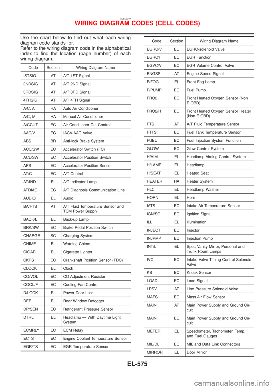
Use the chart below to find out what each wiring
diagram code stands for.
Refer to the wiring diagram code in the alphabetical
index to find the location (page number) of each
wiring diagram.
Code Section Wiring Diagram Name
ISTSIG AT A/T 1ST Signal
2NDSIG AT A/T 2ND Signal
3RDSIG AT A/T 3RD Signal
4THSIG AT A/T 4TH Signal
A/C, A HA Auto Air Conditioner
A/C, M HA Manual Air Conditioner
A/CCUT EC Air Conditioner Cut Control
AAC/V EC IACV-AAC Valve
ABS BR Anti-lock Brake System
ACC/SW EC Accelerator Switch (FC)
ACL/SW EC Accelerator Position Switch
APS EC Accelerator Position Sensor
AT/C EC A/T Control
AT/IND EL A/T Indicator Lamp
ATDIAG EC A/T Diagnosis Communication Line
AUDIO EL Audio
BA/FTS AT A/T Fluid Temperature Sensor and
TCM Power Supply
BACK/L EL Back-up Lamp
BRK/SW EC Brake Pedal Position Switch
CHARGE SC Charging System
CHIME EL Warning Chime
CIGAR EL Cigarette Lighter
CKPS EC Crankshaft Position Sensor (TDC)
CLOCK EL Clock
CO/VOL EC CO Adjustment Resistor
COOL/F EC Cooling Fan Control
D/LOCK EL Power Door Lock
DEF EL Rear Window Defogger
DP/SEN EC Refrigerant Pressure Sensor
DTRL EL Headlamp Ð With Daytime Light
System
ECMRLY EC ECM Relay
ECTS EC Engine Coolant Temperature Sensor
EGR/TS EC EGR Temperature Sensor
Code Section Wiring Diagram Name
EGRC/V EC EGRC-solenoid Valve
EGRC1 EC EGR Function
EGVC/V EC EGR Volume Control Valve
ENGSS AT Engine Speed Signal
F/FOG EL Front Fog Lamp
F/PUMP EC Fuel Pump
FRO2 EC Front Heated Oxygen Sensor (Non
E-OBD)
FRO2/H EC Front Heated Oxygen Sensor Heater
(Non E-OBD)
FTS AT A/T Fluid Temperature Sensor
FTTS EC Fuel Tank Temperature Sensor
FUEL EC Fuel Injection System Function
GLOW EC Glow Control System
H/AIM EL Headlamp Aiming Control System
H/LAMP EL Headlamp
H/SEAT EL Heated Seat
HEATER HA Heater System
HLC EL Headlamp Washer
HORN EL Horn
IATS EC Intake Air Temperature Sensor
IGN/SG EC Ignition Signal
ILL EL Illumination
INJECT EC Injector
INJPMP EC Injection Pump
INT/L EL Spot, Vanity Mirror, Personal and
Trunk Room Lamps
IVC EC Intake Valve Timing Control Solenoid
Valve
KS EC Knock Sensor
LOAD EC Load Signal
LPSV AT Line Pressure Solenoid Valve
MAFS EC Mass Air Flow Sensor
MAIN AT Main Power Supply and Ground Cir-
cuit
MAIN EC Main Power Supply and Ground Cir-
cuit
METER EL Speedometer, Tachometer, Temp.
and Fuel Gauges
MIL/DL EC MIL and Data Link Connectors
MIRROR EL Door Mirror
WIRING DIAGRAM CODES (CELL CODES)
EL-575
Page 2134 of 2898
Code Section Wiring Diagram Name
MULTI EL Multi-remote Control System
NATS EL Nissan Anti-Theft System
NAVI EL Navigation System
NONDTC AT Non-detectable Items
O2H1B1 EC Front Heated Oxygen Sensor Heater
(E-OBD)
O2H2B1 EC Rear Heated Oxygen Sensor Heater
(E-OBD)
O2S1B1 EC Front Heated Oxygen Sensor
(E-OBD)
O2S2B1 EC Rear Heated Oxygen Sensor
(E-OBD)
OVRCSV AT Overrun Clutch Solenoid Valve
P/ANT EL Power Antenna
PGC/V EC EVAP Canister Purge Volume Con-
trol Solenoid Valve
PHASE EC Camshaft Position Sensor (PHASE)
PNP/SW EC Park/Neutral Position Switch
PNP/SW AT Park/Neutral Position Switch
POS EC Crankshaft Position Sensor (POS)
POWER EL Power Supply Routing
PST/SW EC Power Steering Oil Pressure Switch
R/FOG EL Rear Fog Lamp
ROOM/L EL Interior Room Lamp
RRO2 EC Rear Heated Oxygen Sensor (Non
E-OBD)
RRO2/H EC Rear Heated Oxygen Sensor Heater
(Non E-OBD)
S/SIG EC Start Signal
SHIFT AT A/T Shift Lock System
S/LOCK EL Power Door Lock Ð Super Lock Ð
SROOF EL Sunroof
SRS RS Supplemental Restraint System
SSV/A AT Shift Solenoid Valve A
SSV/B AT Shift Solenoid Valve B
START SC Starting System
STOP/L EL Stop Lamp
SWL/C EC Swirl Control Valve Control Solenoid
Valve (Non E-OBD)
SWL/V EC Swirl Control Valve Control Solenoid
Valve (E-OBD)
TAIL/L EL Parking, License and Tail LampsCode Section Wiring Diagram Name
TCV AT Torque Converter Clutch Solenoid
Valve
THEFT EL Theft Warning System
TLID EL Trunk Lid Opener
TP/SW EC Throttle Position Switch
TPS AT Throttle Position Sensor
TPS EC Throttle Position Sensor
TURN EL Turn Signal and Hazard Warning
Lamps
VSS EC Vehicle Speed Sensor
VSSA/T AT Vehicle Speed Sensor A/T (Revolu-
tion Sensor)
VSSMTR AT Vehicle Speed Sensor MTR
WARN EL Warning Lamps
WINDOW EL Power Window
WIP/R EL Rear Wiper and Washer
WIPER EL Front Wiper and Washer
WIRING DIAGRAM CODES (CELL CODES)
EL-576
Page 2272 of 2898
crankshaft position sensor (TDC sensor) from the assem-
bly.
+Always pay extra attention not to damage edge of crank-
shaft position sensor (TDC sensor) or ring gear teeth.
REMOVALNJEM0069S011. Remove engine undercover, and hood for hoisting.
2. Drain coolant from both cylinder block and radiator. Refer to
LC-44, ªChanging Engine Coolantº.
3. Remove the following parts:
+Battery
+RH and LH front wheels
+RH and LH splash covers (combined with undercover)
+Auxiliary belts
+Alternator
+Alternator brackets
+Radiator and cooling fan
+Engine cover
+Air ducts and air cleaner case
LH side of engine room:
4. Disconnect all harnesses and grounds that are connected to
components on vehicle.
5. Disconnect vacuum hose on vacuum pump side.
6. Disconnect fuel feed and fuel return hoses on engine side.
+Immediately put blind plugs into the openings to prevent
fuel from flowing out.
7. Disconnect heater hose. Plug opening of hose to prevent cool-
ant from flowing out.
RH side of engine room:
8. Remove air conditioner compressor from brackets and move
it toward vehicle side. Secure compressor on vehicle side with
rope.
Vehicle underside:
9. Remove exhaust front tube.
10. Disconnect two hoses from power steering pump and plug to
stop fluid.
11. Remove M/T control rod and support rod.
12. Remove ABS wheel sensor, and temporarily hang brake cali-
per with rope on vehicle side.
13. Remove RH and LH drive shafts.
SEM666G
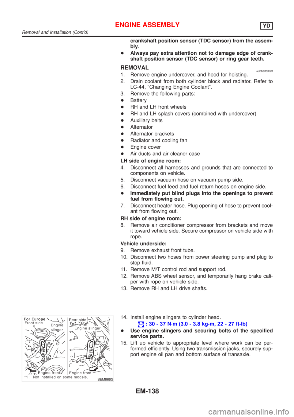
14. Install engine slingers to cylinder head.
: 30 - 37 N´m (3.0 - 3.8 kg-m, 22 - 27 ft-lb)
+Use engine slingers and securing bolts of the specified
service parts.
15. Lift up vehicle to appropriate level where work can be per-
formed efficiently. Using two transmission jacks, securely sup-
port engine oil pan and bottom surface of transaxle.
ENGINE ASSEMBLYYD
Removal and Installation (Cont'd)
EM-138
Page 2354 of 2898
+Do not use gasoline, kerosine, diesel fuel, gas oil, thinners or
solvents for cleaning skin.
+If skin disorders develop, obtain medical advice without delay.
+Where practicable, degrease components prior to handling.
+Where there is a risk of eye contact, eye protection should be
worn, for example, chemical goggles or face shields; in addi-
tion an eye wash facility should be provided.
Environmental Protection PrecautionsNJGI0001S0702Burning used engine oil in small space heaters or boilers can be
recommended only for units of approved design. The heating sys-
tem must meet the requirements of HM Inspectorate of Pollution for
small burners of less than 0.4 MW. If in doubt, check with the
appropriate local authority and/or manufacturer of the approved
appliance.
Dispose of used oil and used oil filters through authorized waste
disposal contractors to licensed waste disposal sites, or to the
waste oil reclamation trade. If in doubt, contact the local authority
for advice on disposal facilities.
It is illegal to pour used oil on to the ground, down sewers or drains,
or into water courses.
The regulations concerning the pollution vary between
regions.
PRECAUTIONS FOR FUELNJGI0001S08Gasoline EngineNJGI0001S0803Models with three way catalyst
Unleaded premium gasoline of at least 95 octane (RON)
If premium gasoline is not available, unleaded regular gaso-
line with an octane rating of 91 (RON) may be temporarily
used, but only under the following precautions:
+Have the fuel tank filled only partially with unleaded regu-
lar gasoline, and fill up with premium unleaded gasoline
as soon as possible.
+Avoid full throttle driving and abrupt acceleration.
CAUTION:
Do not use leaded gasoline. Using leaded gasoline will dam-
age the three way catalyst.
Diesel Engine*:NJGI0001S0804Diesel fuel of at least 50 cetane
* If two types of diesel fuel are available, use summer or winter
fuel properly according to the following temperature conditions.
+Above þ7ÉC (20ÉF) ... Summer type diesel fuel.
+Below þ7ÉC (20ÉF) ... Winter type diesel fuel.
CAUTION:
+Do not use home heating oil, gasoline, or other alternate
fuels in your diesel engine. The use of those can cause
engine damage.
+Do not use summer fuel at temperatures below þ7ÉC
(20ÉF). The cold temperatures will cause wax to form in the
fuel. As a result, it may prevent the engine from running
smoothly.
+Do not add gasoline or other alternate fuels to diesel fuel.
PRECAUTIONS FOR AIR CONDITIONINGNJGI0001S09Use an approved refrigerant recovery unit any time the air condi-
tioning system must be discharged. Refer to HA-78, ªHFC-134a
(R-134a) Service Procedureº for specific instructions.
PRECAUTIONS
Precautions (Cont'd)
GI-8
Page 2396 of 2898
NJGI0011
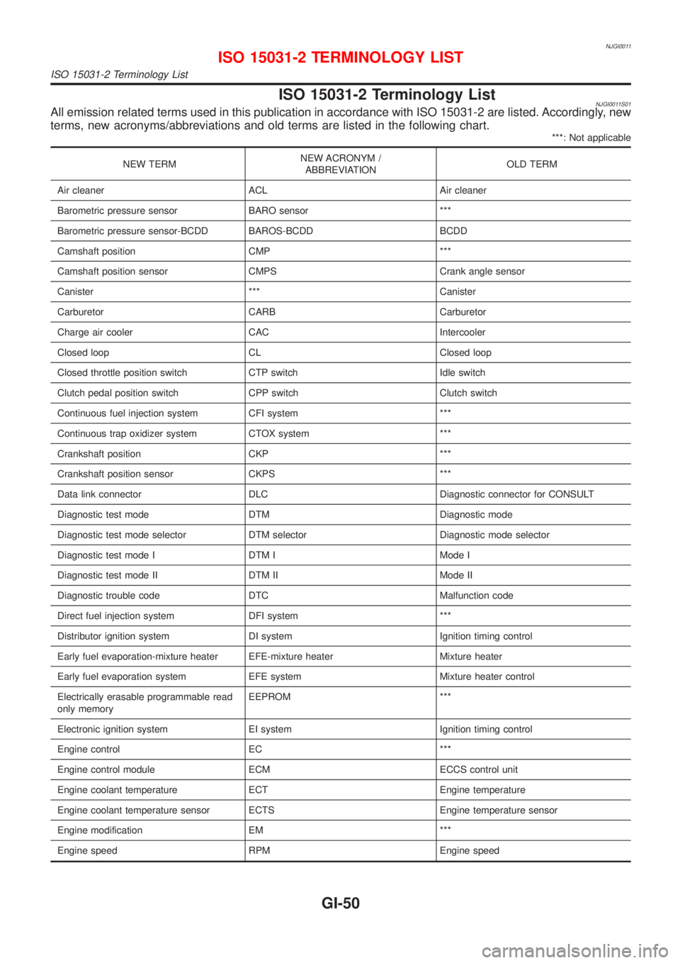
ISO 15031-2 Terminology ListNJGI0011S01All emission related terms used in this publication in accordance with ISO 15031-2 are listed. Accordingly, new
terms, new acronyms/abbreviations and old terms are listed in the following chart.
***: Not applicable
NEW TERMNEW ACRONYM /
ABBREVIATIONOLD TERM
Air cleaner ACL Air cleaner
Barometric pressure sensor BARO sensor ***
Barometric pressure sensor-BCDD BAROS-BCDD BCDD
Camshaft position CMP ***
Camshaft position sensor CMPS Crank angle sensor
Canister *** Canister
Carburetor CARB Carburetor
Charge air cooler CAC Intercooler
Closed loop CL Closed loop
Closed throttle position switch CTP switch Idle switch
Clutch pedal position switch CPP switch Clutch switch
Continuous fuel injection system CFI system ***
Continuous trap oxidizer system CTOX system ***
Crankshaft position CKP ***
Crankshaft position sensor CKPS ***
Data link connector DLC Diagnostic connector for CONSULT
Diagnostic test mode DTM Diagnostic mode
Diagnostic test mode selector DTM selector Diagnostic mode selector
Diagnostic test mode I DTM I Mode I
Diagnostic test mode II DTM II Mode II
Diagnostic trouble code DTC Malfunction code
Direct fuel injection system DFI system ***
Distributor ignition system DI system Ignition timing control
Early fuel evaporation-mixture heater EFE-mixture heater Mixture heater
Early fuel evaporation system EFE system Mixture heater control
Electrically erasable programmable read
only memoryEEPROM ***
Electronic ignition system EI system Ignition timing control
Engine control EC ***
Engine control module ECM ECCS control unit
Engine coolant temperature ECT Engine temperature
Engine coolant temperature sensor ECTS Engine temperature sensor
Engine modification EM ***
Engine speed RPM Engine speed
ISO 15031-2 TERMINOLOGY LIST
ISO 15031-2 Terminology List
GI-50
Page 2401 of 2898
HEATER &
AIR CONDITIONER
SECTION
HA
CONTENTS
PRECAUTIONS...............................................................2
Supplemental Restraint System (SRS)²AIR
BAG²and²SEAT BELT PRE-TENSIONER²...............2
Precautions for Working with HFC-134a (R-134a) .....2
General Refrigerant Precautions .................................2
Precautions for Refrigerant Connection ......................3
Precautions for Servicing Compressor ........................5
Precautions for Service Equipment .............................6
Wiring Diagrams and Trouble Diagnosis .....................8
PREPARATION...............................................................9
Special Service Tools ..................................................9
HFC-134a (R-134a) Service Tools and
Equipment .................................................................. 11
DESCRIPTION...............................................................13
Refrigeration System .................................................13
CSV613 Variable Displacement Compressor............14
Component Layout ....................................................18
Control Operation ......................................................19
Discharge Air Flow.....................................................20
System Description ....................................................21
TROUBLE DIAGNOSES................................................22
Component Location..................................................22
Wiring Diagram - Heater............................................24
Circuit Diagram - Air Conditioner...............................26
Wiring Diagram - A/C, M - .........................................27
How to Perform Trouble Diagnoses for Quick
and Accurate Repair ..................................................33
Operational Check .....................................................34
Intake Door ................................................................36
Mode Door .................................................................40Air Mix Door ...............................................................42
Max Hot Door (For Scandinavia and Cold Spec
Models) ......................................................................44
Blower Motor..............................................................48
Magnet Clutch............................................................55
Insufficient Cooling ....................................................68
Insufficient Heating ....................................................76
Noise ..........................................................................77
SERVICE PROCEDURE................................................78
HFC-134a (R-134a) Service Procedure ....................78
Maintenance of Lubricant Quantity in
Compressor ...............................................................80
Compressor ...............................................................83
Compressor Clutch - CSV613 (CALSONIC
make) .........................................................................84
Heater & Cooling Unit (Heater Core) ........................88
A/C Evaporator ..........................................................88
Blower Unit ................................................................89
Refrigerant Lines .......................................................91
Belt .............................................................................95
Idle Air Control Valve (IACV) - Auxiliary Air
Control (AAC) Valve ..................................................96
Ventilation Air Filter ....................................................96
SERVICE DATA AND SPECIFICATIONS (SDS).........97
Compressor ...............................................................97
Lubricant ....................................................................97
Refrigerant .................................................................97
Engine Idling Speed (When A/C is On).....................97
Belt Tension ...............................................................97