2001 NISSAN ALMERA heater
[x] Cancel search: heaterPage 726 of 2898

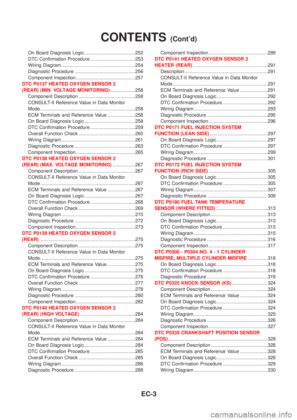
DTC P0100 MASS AIR FLOW SENSOR (MAFS)......187
Component Description ...........................................187
CONSULT-II Reference Value in Data Monitor
Mode ........................................................................187
ECM Terminals and Reference Value .....................187
On Board Diagnosis Logic.......................................187
Fail-safe Mode .........................................................188
DTC Confirmation Procedure ..................................188
Wiring Diagram ........................................................189
Diagnostic Procedure ..............................................191
Component Inspection .............................................193
DTC P0110 INTAKE AIR TEMPERATURE
SENSOR......................................................................194
Component Description ...........................................194
On Board Diagnosis Logic.......................................195
DTC Confirmation Procedure ..................................195
Wiring Diagram ........................................................196
Diagnostic Procedure ..............................................198
Component Inspection .............................................200
DTC P0115 ENGINE COOLANT TEMPERATURE
SENSOR......................................................................201
Component Description ...........................................201
CONSULT-II Reference Value in Data Monitor
Mode ........................................................................201
On Board Diagnosis Logic.......................................201
Fail-safe Mode .........................................................202
DTC Confirmation Procedure ..................................202
Wiring Diagram ........................................................203
Diagnostic Procedure ..............................................205
Component Inspection .............................................206
DTC P0120 THROTTLE POSITION SENSOR...........207
Component Description ...........................................207
CONSULT-II Reference Value in Data Monitor
Mode ........................................................................207
ECM Terminals and Reference Value .....................208
On Board Diagnosis Logic.......................................208
Fail-safe Mode .........................................................208
DTC Confirmation Procedure ..................................208
Wiring Diagram ........................................................210
Diagnostic Procedure ..............................................212
Component Inspection .............................................214
DTC P0130 HEATED OXYGEN SENSOR 1
(FRONT) (CIRCUIT).....................................................216
Component Description ...........................................216
CONSULT-II Reference Value in Data Monitor
Mode ........................................................................216
ECM Terminals and Reference Value .....................216
On Board Diagnosis Logic.......................................217
DTC Confirmation Procedure ..................................217
Overall Function Check ...........................................218
Wiring Diagram ........................................................219
Diagnostic Procedure ..............................................221Component Inspection .............................................222
DTC P0131 HEATED OXYGEN SENSOR 1
(FRONT) (LEAN SHIFT MONITORING).....................224
Component Description ...........................................224
CONSULT-II Reference Value in Data Monitor
Mode ........................................................................224
ECM Terminals and Reference Value .....................224
On Board Diagnosis Logic.......................................225
DTC Confirmation Procedure ..................................225
Overall Function Check ...........................................226
Diagnostic Procedure ..............................................226
Component Inspection .............................................228
DTC P0132 HEATED OXYGEN SENSOR 1
(FRONT) (RICH SHIFT MONITORING)......................230
Component Description ...........................................230
CONSULT-II Reference Value in Data Monitor
Mode ........................................................................230
ECM Terminals and Reference Value .....................230
On Board Diagnosis Logic.......................................231
DTC Confirmation Procedure ..................................231
Overall Function Check ...........................................232
Diagnostic Procedure ..............................................232
Component Inspection .............................................234
DTC P0133 HEATED OXYGEN SENSOR 1
(FRONT).......................................................................236
Component Description ...........................................236
CONSULT-II Reference Value in Data Monitor
Mode ........................................................................236
ECM Terminals and Reference Value .....................236
On Board Diagnosis Logic.......................................237
DTC Confirmation Procedure ..................................237
Overall Function Check ...........................................238
Wiring Diagram ........................................................239
Diagnostic Procedure ..............................................241
Component Inspection .............................................243
DTC P0134 HEATED OXYGEN SENSOR 1
(FRONT) (HIGH VOLTAGE)........................................245
Component Description ...........................................245
CONSULT-II Reference Value in Data Monitor
Mode ........................................................................245
ECM Terminals and Reference Value .....................245
On Board Diagnosis Logic.......................................246
DTC Confirmation Procedure ..................................246
Wiring Diagram ........................................................247
Diagnostic Procedure ..............................................249
Component Inspection .............................................250
DTC P0135 HEATED OXYGEN SENSOR 1
(FRONT) HEATER.......................................................252
Description ...............................................................252
CONSULT-II Reference Value in Data Monitor
Mode ........................................................................252
ECM Terminals and Reference Value .....................252
CONTENTS(Cont'd)
EC-2
Page 727 of 2898

On Board Diagnosis Logic.......................................252
DTC Confirmation Procedure ..................................253
Wiring Diagram ........................................................254
Diagnostic Procedure ..............................................256
Component Inspection .............................................257
DTC P0137 HEATED OXYGEN SENSOR 2
(REAR) (MIN. VOLTAGE MONITORING)...................258
Component Description ...........................................258
CONSULT-II Reference Value in Data Monitor
Mode ........................................................................258
ECM Terminals and Reference Value .....................258
On Board Diagnosis Logic.......................................258
DTC Confirmation Procedure ..................................259
Overall Function Check ...........................................260
Wiring Diagram ........................................................261
Diagnostic Procedure ..............................................263
Component Inspection .............................................265
DTC P0138 HEATED OXYGEN SENSOR 2
(REAR) (MAX. VOLTAGE MONITORING).................267
Component Description ...........................................267
CONSULT-II Reference Value in Data Monitor
Mode ........................................................................267
ECM Terminals and Reference Value .....................267
On Board Diagnosis Logic.......................................267
DTC Confirmation Procedure ..................................268
Overall Function Check ...........................................269
Wiring Diagram ........................................................270
Diagnostic Procedure ..............................................272
Component Inspection .............................................273
DTC P0139 HEATED OXYGEN SENSOR 2
(REAR).........................................................................275
Component Description ...........................................275
CONSULT-II Reference Value in Data Monitor
Mode ........................................................................275
ECM Terminals and Reference Value .....................275
On Board Diagnosis Logic.......................................275
DTC Confirmation Procedure ..................................276
Overall Function Check ...........................................277
Wiring Diagram ........................................................278
Diagnostic Procedure ..............................................280
Component Inspection .............................................282
DTC P0140 HEATED OXYGEN SENSOR 2
(REAR) (HIGH VOLTAGE)..........................................284
Component Description ...........................................284
CONSULT-II Reference Value in Data Monitor
Mode ........................................................................284
ECM Terminals and Reference Value .....................284
On Board Diagnosis Logic.......................................284
DTC Confirmation Procedure ..................................285
Overall Function Check ...........................................285
Wiring Diagram ........................................................286
Diagnostic Procedure ..............................................288Component Inspection .............................................289
DTC P0141 HEATED OXYGEN SENSOR 2
HEATER (REAR).........................................................291
Description ...............................................................291
CONSULT-II Reference Value in Data Monitor
Mode ........................................................................291
ECM Terminals and Reference Value .....................291
On Board Diagnosis Logic.......................................292
DTC Confirmation Procedure ..................................292
Wiring Diagram ........................................................293
Diagnostic Procedure ..............................................295
Component Inspection .............................................296
DTC P0171 FUEL INJECTION SYSTEM
FUNCTION (LEAN SIDE)............................................297
On Board Diagnosis Logic.......................................297
DTC Confirmation Procedure ..................................297
Wiring Diagram ........................................................299
Diagnostic Procedure ..............................................301
DTC P0172 FUEL INJECTION SYSTEM
FUNCTION (RICH SIDE).............................................305
On Board Diagnosis Logic.......................................305
DTC Confirmation Procedure ..................................305
Wiring Diagram ........................................................307
Diagnostic Procedure ..............................................309
DTC P0180 FUEL TANK TEMPERATURE
SENSOR (WHERE FITTED)........................................313
Component Description ...........................................313
On Board Diagnosis Logic.......................................313
DTC Confirmation Procedure ..................................313
Wiring Diagram ........................................................315
Diagnostic Procedure ..............................................316
Component Inspection .............................................317
DTC P0300 - P0304 NO.4-1CYLINDER
MISFIRE, MULTIPLE CYLINDER MISFIRE...............318
On Board Diagnosis Logic.......................................318
DTC Confirmation Procedure ..................................318
Diagnostic Procedure ..............................................319
DTC P0325 KNOCK SENSOR (KS)...........................324
Component Description ...........................................324
ECM Terminals and Reference Value .....................324
On Board Diagnosis Logic.......................................324
DTC Confirmation Procedure ..................................324
Wiring Diagram ........................................................325
Diagnostic Procedure ..............................................326
Component Inspection .............................................327
DTC P0335 CRANKSHAFT POSITION SENSOR
(POS)............................................................................328
Component Description ...........................................328
ECM Terminals and Reference Value .....................328
On Board Diagnosis Logic.......................................329
DTC Confirmation Procedure ..................................329
Wiring Diagram ........................................................330
CONTENTS(Cont'd)
EC-3
Page 729 of 2898

DTC Confirmation Procedure ..................................400
Wiring Diagram ........................................................402
Diagnostic Procedure ..............................................403
Component Inspection .............................................404
DTC P1217 OVERHEAT (COOLING SYSTEM).........406
System Description ..................................................406
CONSULT-II Reference Value in Data Monitor
Mode ........................................................................406
ECM Terminals and Reference Value .....................407
On Board Diagnosis Logic.......................................407
Overall Function Check ...........................................408
Wiring Diagram ........................................................409
Diagnostic Procedure ..............................................410
Main 12 Causes of Overheating..............................416
Component Inspection .............................................416
DTC P1401 EGR TEMPERATURE SENSOR
(WHERE FITTED)........................................................418
Component Description ...........................................418
On Board Diagnosis Logic.......................................418
DTC Confirmation Procedure ..................................418
Wiring Diagram ........................................................421
Diagnostic Procedure ..............................................423
Component Inspection .............................................424
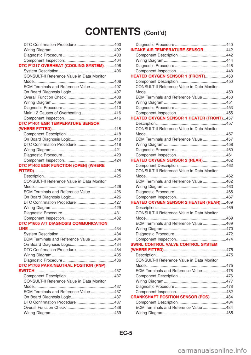
DTC P1402 EGR FUNCTION (OPEN) (WHERE
FITTED)........................................................................425
Description ...............................................................425
CONSULT-II Reference Value in Data Monitor
Mode ........................................................................426
ECM Terminals and Reference Value .....................426
On Board Diagnosis Logic.......................................426
DTC Confirmation Procedure ..................................427
Wiring Diagram ........................................................429
Diagnostic Procedure ..............................................431
Component Inspection .............................................432
DTC P1605 A/T DIAGNOSIS COMMUNICATION
LINE.............................................................................434
System Description ..................................................434
ECM Terminals and Reference Value .....................434
On Board Diagnosis Logic.......................................434
DTC Confirmation Procedure ..................................434
Wiring Diagram ........................................................435
Diagnostic Procedure ..............................................436
DTC P1706 PARK/NEUTRAL POSITION (PNP)
SWITCH.......................................................................437
Component Description ...........................................437
CONSULT-II Reference Value in Data Monitor
Mode ........................................................................437
ECM Terminals and Reference Value .....................437
On Board Diagnosis Logic.......................................437
DTC Confirmation Procedure ..................................437
Overall Function Check ...........................................438
Wiring Diagram ........................................................439Diagnostic Procedure ..............................................440
INTAKE AIR TEMPERATURE SENSOR....................442
Component Description ...........................................442
Wiring Diagram ........................................................444
Diagnostic Procedure ..............................................446
Component Inspection .............................................448
HEATED OXYGEN SENSOR 1 (FRONT)...................450
Component Description ...........................................450
CONSULT-II Reference Value in Data Monitor
Mode ........................................................................450
ECM Terminals and Reference Value .....................450
Wiring Diagram ........................................................451
Diagnostic Procedure ..............................................453
Component Inspection .............................................455
HEATED OXYGEN SENSOR 1 HEATER (FRONT)...457
Description ...............................................................457
CONSULT-II Reference Value in Data Monitor
Mode ........................................................................457
ECM Terminals and Reference Value .....................457
Wiring Diagram ........................................................458
Diagnostic Procedure ..............................................460
Component Inspection .............................................461
HEATED OXYGEN SENSOR 2 (REAR).....................462
Component Description ...........................................462
CONSULT-II Reference Value in Data Monitor
Mode ........................................................................462
ECM Terminals and Reference Value .....................462
Wiring Diagram ........................................................463
Diagnostic Procedure ..............................................465
Component Inspection .............................................467
HEATED OXYGEN SENSOR 2 HEATER (REAR).....469
Description ...............................................................469
CONSULT-II Reference Value in Data Monitor
Mode ........................................................................469
ECM Terminals and Reference Value .....................469
Wiring Diagram ........................................................470
Diagnostic Procedure ..............................................472
Component Inspection .............................................474
SWIRL CONTROL VALVE CONTROL SYSTEM
(WHERE FITTED)........................................................475
Description ...............................................................475
CONSULT-II Reference Value in Data Monitor
Mode ........................................................................475
ECM Terminals and Reference Value .....................476
Component Description ...........................................476
Wiring Diagram ........................................................477
Diagnostic Procedure ..............................................478
Component Inspection .............................................482
CRANKSHAFT POSITION SENSOR (POS)...............484
Component Description ...........................................484
ECM Terminals and Reference Value .....................484
Wiring Diagram ........................................................485
CONTENTS(Cont'd)
EC-5
Page 731 of 2898

ECM Terminals and Reference Value .....................578
Wiring Diagram ........................................................579
Diagnostic Procedure - Load Signal - .....................583
Diagnostic Procedure - Heater Control Panel
(Fan Switch) - ..........................................................589
Component Inspection .............................................590
MI & DATA LINK CONNECTORS..............................591
Wiring Diagram ........................................................591
SERVICE DATA AND SPECIFICATIONS (SDS).......593
Fuel Pressure Regulator..........................................593
Idle Speed and Ignition Timing ................................593
Mass Air Flow Sensor..............................................593
Intake Air Temperature Sensor ................................593
Engine Coolant Temperature Sensor ......................593
Throttle Position Sensor ..........................................593
Heated Oxygen Sensor 1 Heater (Front) ................593
Heated Oxygen Sensor 2 Heater (Rear).................593
Fuel Tank Temperature Sensor (Where Fitted) .......594
EGR Volume Control Valve (Where Fitted) .............594
EGR Temperature Sensor (Where Fitted) ...............594
EVAP Canister Purge Volume Control Valve ..........594
IACV-AAC Valve ......................................................594
Injector .....................................................................594
Ignition Coil with Power Transistor ..........................594
Condenser ...............................................................594
Fuel Pump ...............................................................594
Crankshaft Position Sensor (POS) ..........................595
Camshaft Position Sensor (PHASE) .......................595
YD
TROUBLE DIAGNOSIS - INDEX................................596
Alphabetical & P No. Index for DTC .......................596
PRECAUTIONS...........................................................598
Supplemental Restraint System (SRS)²AIR
BAG²and²SEAT BELT PRE-TENSIONER²...........598
Engine Fuel & Emission Control System ................599
Precautions ..............................................................600
Wiring Diagrams and Trouble Diagnosis .................601
PREPARATION...........................................................602
Special Service Tools ..............................................602
ENGINE AND EMISSION CONTROL OVERALL
SYSTEM.......................................................................603
Engine Control Component Parts Location .............603
Circuit Diagram ........................................................606
System Diagram ......................................................608
System Chart ...........................................................609
ENGINE AND EMISSION BASIC CONTROL
SYSTEM DESCRIPTION.............................................610
Fuel Injection Control System .................................610
Fuel Injection Timing Control System...................... 611
Air Conditioning Cut Control ....................................612Fuel Cut Control (at no load & high engine
speed) ......................................................................612
Crankcase Ventilation System .................................613
BASIC SERVICE PROCEDURE.................................614
Injection Tube and Injection Nozzle ........................614
Electronic Control Fuel Injection Pump ...................618
Fuel Filter .................................................................625
ON BOARD DIAGNOSTIC SYSTEM
DESCRIPTION.............................................................627
DTC and MI Detection Logic ...................................627
Diagnostic Trouble Code (DTC) ..............................627
Malfunction Indicator (MI) ........................................628
CONSULT-II .............................................................632
TROUBLE DIAGNOSIS - INTRODUCTION................637
Introduction ..............................................................637
Work Flow ................................................................639
TROUBLE DIAGNOSIS - BASIC INSPECTION.........641
Basic Inspection.......................................................641
TROUBLE DIAGNOSIS - GENERAL
DESCRIPTION.............................................................646
Symptom Matrix Chart .............................................646
CONSULT-II Reference Value in Data Monitor
Mode ........................................................................656
Major Sensor Reference Graph in Data Monitor
Mode ........................................................................658
ECM Terminals and Reference Value .....................659
TROUBLE DIAGNOSIS FOR INTERMITTENT
INCIDENT.....................................................................665
Description ...............................................................665
Diagnostic Procedure ..............................................665
TROUBLE DIAGNOSIS FOR POWER SUPPLY........666
Main Power Supply and Ground Circuit ..................666
DTC P0100 MASS AIR FLOW SEN...........................673
Component Description ...........................................673
CONSULT-II Reference Value in Data Monitor
Mode ........................................................................673
ECM Terminals and Reference Value .....................673
On Board Diagnosis Logic.......................................673
DTC Confirmation Procedure ..................................673
Wiring Diagram ........................................................675
Diagnostic Procedure ..............................................677
DTC P0115 COOLANT TEMP SEN............................680
Description ...............................................................680
On Board Diagnosis Logic.......................................680
DTC Confirmation Procedure ..................................680
Wiring Diagram ........................................................682
Diagnostic Procedure ..............................................683
DTC P0120 ACCEL POS SENSOR............................685
Description ...............................................................685
CONSULT-II Reference Value in Data Monitor
Mode ........................................................................685
ECM Terminals and Reference Value .....................685
CONTENTS(Cont'd)
EC-7
Page 755 of 2898

System ChartNJEC0013
Input (Sensor) ECM Function Output (Actuator)
+Camshaft position sensor (PHASE)
+Crankshaft position sensor (POS)
+Mass air flow sensor
+Engine coolant temperature sensor
+Heated oxygen sensor 1 (front)
+Ignition switch
+Throttle position sensor
+PNP switch
+Air conditioner switch
+Knock sensor
+EGR temperature sensor*1, *4
+Fuel tank temperature sensor*1, *4
+Battery voltage
+Power steering oil pressure switch
+Vehicle speed sensor
+Intake air temperature sensor
+Heated oxygen sensor 2 (rear)*2
+TCM (Transmission Control Module)*3
+Closed throttle position switch
+Electrical load
+Refrigerant pressure sensorFuel injection & mixture ratio control Injectors
Electronic ignition system Power transistor
Idle air control system IACV-AAC valve
Intake valve timing controlIntake valve timing control sole-
noid valve
Fuel pump control Fuel pump relay
On board diagnostic systemMalfunction indicator
(On the instrument panel)
EGR control*4 EGR volume control valve*4
Heated oxygen sensor 1/2 heater (front/
rear) controlHeated oxygen sensor 1/2 heater
(front/rear)
EVAP canister purge flow controlEVAP canister purge volume con-
trol solenoid valve
Cooling fan control Cooling fan relay
Air conditioning cut control Air conditioner relay
Swirl control valve control*4Swirl control valve control sole-
noid*4
*1: These sensors are not used to control the engine system. They are used only for the on board diagnosis.
*2: Under normal conditions, this sensor is not for engine control operation.
*3: The DTC related to A/T will be sent to ECM.
*4: If so equipped
ENGINE AND EMISSION CONTROL OVERALL SYSTEMQG
System Chart
EC-31
Page 769 of 2898

h)Fuel pressure
i)Engine compression
j)EGR valve operation
k)Throttle valve
l)EVAP system
+On models equipped with air conditioner, checks should
be carried out while the air conditioner is ªOFFº.
+When checking idle speed on models equipped with A/T,
ignition timing and mixture ratio, checks should be carried
out while shift lever is in ªPº or ªNº position.
+When measuring ªCOº percentage, insert probe more
than 40 cm (15.7 in) into tail pipe.
+Turn off headlamps, heater blower, rear window defogger.
+On vehicles equipped with daytime light systems, set
lighting switch to the 1st position to light only small
lamps.
+Keep front wheels pointed straight ahead.
+If engine stops immediately after starting or idle condition
is unstable, perform the following to initialize IACV-AAC
valve:
a)Stop engine and wait 9 seconds.
b)Turn ignition ªONº and wait 1 second.
c)Turn ignition ªOFFº and wait 9 seconds.
+Make sure the cooling fan has stopped.
BASIC SERVICE PROCEDUREQG
Preparation (Cont'd)
EC-45
Page 786 of 2898

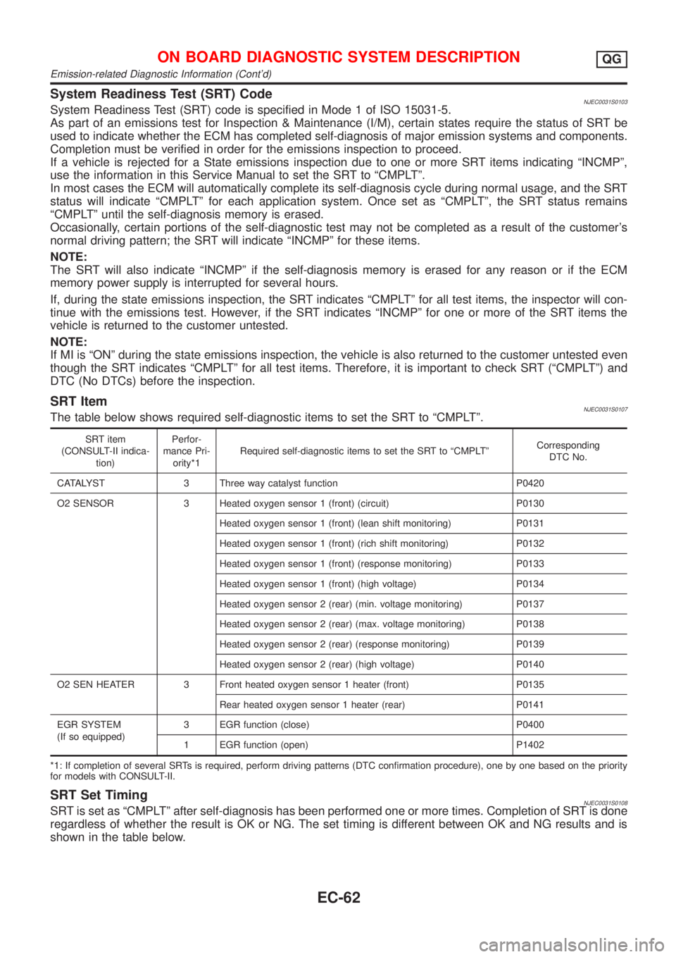
System Readiness Test (SRT) CodeNJEC0031S0103System Readiness Test (SRT) code is specified in Mode 1 of ISO 15031-5.
As part of an emissions test for Inspection & Maintenance (I/M), certain states require the status of SRT be
used to indicate whether the ECM has completed self-diagnosis of major emission systems and components.
Completion must be verified in order for the emissions inspection to proceed.
If a vehicle is rejected for a State emissions inspection due to one or more SRT items indicating ªINCMPº,
use the information in this Service Manual to set the SRT to ªCMPLTº.
In most cases the ECM will automatically complete its self-diagnosis cycle during normal usage, and the SRT
status will indicate ªCMPLTº for each application system. Once set as ªCMPLTº, the SRT status remains
ªCMPLTº until the self-diagnosis memory is erased.
Occasionally, certain portions of the self-diagnostic test may not be completed as a result of the customer's
normal driving pattern; the SRT will indicate ªINCMPº for these items.
NOTE:
The SRT will also indicate ªINCMPº if the self-diagnosis memory is erased for any reason or if the ECM
memory power supply is interrupted for several hours.
If, during the state emissions inspection, the SRT indicates ªCMPLTº for all test items, the inspector will con-
tinue with the emissions test. However, if the SRT indicates ªINCMPº for one or more of the SRT items the
vehicle is returned to the customer untested.
NOTE:
If MI is ªONº during the state emissions inspection, the vehicle is also returned to the customer untested even
though the SRT indicates ªCMPLTº for all test items. Therefore, it is important to check SRT (ªCMPLTº) and
DTC (No DTCs) before the inspection.
SRT ItemNJEC0031S0107The table below shows required self-diagnostic items to set the SRT to ªCMPLTº.
SRT item
(CONSULT-II indica-
tion)Perfor-
mance Pri-
ority*1Required self-diagnostic items to set the SRT to ªCMPLTºCorresponding
DTC No.
CATALYST 3 Three way catalyst function P0420
O2 SENSOR 3 Heated oxygen sensor 1 (front) (circuit) P0130
Heated oxygen sensor 1 (front) (lean shift monitoring) P0131
Heated oxygen sensor 1 (front) (rich shift monitoring) P0132
Heated oxygen sensor 1 (front) (response monitoring) P0133
Heated oxygen sensor 1 (front) (high voltage) P0134
Heated oxygen sensor 2 (rear) (min. voltage monitoring) P0137
Heated oxygen sensor 2 (rear) (max. voltage monitoring) P0138
Heated oxygen sensor 2 (rear) (response monitoring) P0139
Heated oxygen sensor 2 (rear) (high voltage) P0140
O2 SEN HEATER 3 Front heated oxygen sensor 1 heater (front) P0135
Rear heated oxygen sensor 1 heater (rear) P0141
EGR SYSTEM
(If so equipped)3 EGR function (close) P0400
1 EGR function (open) P1402
*1: If completion of several SRTs is required, perform driving patterns (DTC confirmation procedure), one by one based on the priority
for models with CONSULT-II.
SRT Set TimingNJEC0031S0108SRT is set as ªCMPLTº after self-diagnosis has been performed one or more times. Completion of SRT is done
regardless of whether the result is OK or NG. The set timing is different between OK and NG results and is
shown in the table below.
ON BOARD DIAGNOSTIC SYSTEM DESCRIPTIONQG
Emission-related Diagnostic Information (Cont'd)
EC-62
Page 792 of 2898

SRT item Self-diagnostic test itemTest value (GST display)
Test limit Application
TID CID
HO2SHeated oxygen sensor 1
(front)09H 04H Max. X
0AH 84H Min. X
0BH 04H Max. X
0CH 04H Max. X
0DH 04H Max. X
Heated oxygen sensor 2
(rear)19H 86H Min. X
1AH 86H Min. X
1BH 06H Max. X
1CH 06H Max. X
HO2S HTRHeated oxygen sensor 1
heater (front)29H 08H Max. X
2AH 88H Min. X
Heated oxygen sensor 2
heater (rear)2DH 0AH Max. X
2EH 8AH Min. X
EGR SYSTEM
(where fitted)EGR function31H 8CH Min. X
32H 8CH Min. X
33H 8CH Min. X
34H 8CH Min. X
35H 0CH Max. X
Emission-related Diagnostic Information ItemsNJEC0031S0105X: Applicable Ð: Not applicable
Items
(CONSULT-II screen terms)DTC*1 SRT codeTest value/Test
limit
(GST only)1st trip DTC*1 Reference page
NO SELF DIAGNOSTIC FAIL-
URE INDICATEDP0000ÐÐÐÐ
MAF SEN/CIRCUIT P0100 Ð Ð X EC-187
AIR TEMP SEN/CIRC P0110 Ð Ð X EC-194
COOLANT T SEN/CIRC P0115 Ð Ð X EC-201
THRTL POS SEN/CIRC P0120 Ð Ð X EC-207
HO2S1 (B1) P0130 X X X*2 EC-216
HO2S1 (B1) P0131 X X X*2 EC-224
HO2S1 (B1) P0132 X X X*2 EC-230
HO2S1 (B1) P0133 X X X*2 EC-236
HO2S1 (B1) P0134 X X X*2 EC-245
HO2S1 HTR (B1) P0135 X X X*2 EC-252
HO2S2 (B1) P0137 X X X*2 EC-258
HO2S2 (B1) P0138 X X X*2 EC-267
HO2S2 (B1) P0139 X X X*2 EC-275
ON BOARD DIAGNOSTIC SYSTEM DESCRIPTIONQG
Emission-related Diagnostic Information (Cont'd)
EC-68