Page 2413 of 2898

Refrigeration System
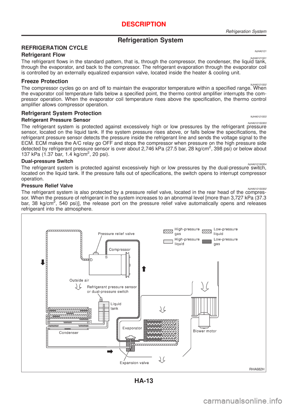
REFRIGERATION CYCLENJHA0121Refrigerant FlowNJHA0121S01The refrigerant flows in the standard pattern, that is, through the compressor, the condenser, the liquid tank,
through the evaporator, and back to the compressor. The refrigerant evaporation through the evaporator coil
is controlled by an externally equalized expansion valve, located inside the heater & cooling unit.
Freeze ProtectionNJHA0121S02The compressor cycles go on and off to maintain the evaporator temperature within a specified range. When
the evaporator coil temperature falls below a specified point, the thermo control amplifier interrupts the com-
pressor operation. When the evaporator coil temperature rises above the specification, the thermo control
amplifier allows compressor operation.
Refrigerant System ProtectionNJHA0121S03Refrigerant Pressure SensorNJHA0121S0303The refrigerant system is protected against excessively high or low pressures by the refrigerant pressure
sensor, located on the liquid tank. If the system pressure rises above, or falls below the specifications, the
refrigerant pressure sensor detects the pressure inside the refrigerant line and sends the voltage signal to the
ECM. ECM makes the A/C relay go OFF and stops the compressor when pressure on the high pressure side
detected by refrigerant pressure sensor is over about 2,746 kPa (27.5 bar, 28 kg/cm
2, 398 psi) or below about
137 kPa (1.37 bar, 1.4 kg/cm2, 20 psi).
Dual-pressure Switch
NJHA0121S0304The refrigerant system is protected against excessively high or low pressures by the dual-pressure switch,
located on the liquid tank. If the pressure falls out of specifications, the switch opens to interrupt compressor
operation.
Pressure Relief Valve
NJHA0121S0302The refrigerant system is also protected by a pressure relief valve, located in the rear head of the compres-
sor. When the pressure of refrigerant in the system increases to an abnormal level [more than 3,727 kPa (37.3
bar, 38 kg/cm
2, 540 psi)], the release port on the pressure relief valve automatically opens and releases
refrigerant into the atmosphere.
RHA682H
DESCRIPTION
Refrigeration System
HA-13
Page 2424 of 2898
Wiring Diagram Ð HeaterNJHA02024-DOOR SEDANNJHA0202S02
HHA211
TROUBLE DIAGNOSES
Wiring Diagram Ð Heater
HA-24
Page 2425 of 2898
HATCHBACKNJHA0202S03
NHA476
TROUBLE DIAGNOSES
Wiring Diagram Ð Heater (Cont'd)
HA-25
Page 2437 of 2898
RHA623H
COMPONENT DESCRIPTIONNJHA0209Intake Door MotorNJHA0209S01The intake door motor is attached to the intake unit. It rotates so
that air is drawn from inlets set by the heater control panel. Motor
rotation is conveyed to a lever which activates the intake door.
DIAGNOSTIC PROCEDURE FOR INTAKE DOOR
MOTOR CIRCUIT
NJHA0210
1 CHECK POWER SUPPLY FOR HEATER CONTROL PANEL
Do approx. 12 volts exist between heater control panel harness terminal No. 1 and body ground?
NHA483
YesorNo
Ye s©GO TO 2.
No©Check 10A (No. 15) fuse at fuse block. Refer to Sedan: EL-11 (QG), EL-19 (YD), Hatch-
back: EL-28, ªWiring Diagram Ð POWER к.
2 CHECK RECIRCULATION (REC) SWITCH
Refer to HA-39.
OK or NG
OK©GO TO 3.
NG©Replace recirculation (REC) switch.
TROUBLE DIAGNOSES
Intake Door (Cont'd)
HA-37
Page 2438 of 2898
3 CHECK GROUND CIRCUIT FOR RECIRCULATION (REC) SWITCH
Check circuit continuity between heater control panel harness terminal No. 5 and body ground.
NHA484
Continuity should exist.
If OK, check harness for short.
OK or NG
OK©GO TO 4.
Ng©Repair harness or connector.
4 CHECK POWER SUPPLY FOR INTAKE DOOR MOTOR
Do approx. 12 volts exist between intake door motor harness terminal No. 1, 2 and body ground?
RHA758H
YesorNo
Ye s©Replace intake door motor.
No©GO TO 5.
TROUBLE DIAGNOSES
Intake Door (Cont'd)
HA-38
Page 2439 of 2898
5 CHECK CIRCUIT CONTINUITY BETWEEN HEATER CONTROL PANEL AND INTAKE DOOR MOTOR
Check circuit continuity between heater control panel harness terminal No. 10 (11) and intake door motor harness terminal
No. 2 (1)
NHA485
Continuity should exist.
If OK, check harness for short.
OK or NG
OK©Replace heater control panel.
NG©Repair harness or connector.
NHA486
ELECTRICAL COMPONENT INSPECTIONNJHA0216Recirculation (REC) SwitchNJHA0216S01Check continuity between terminals.
Terminals REC switch Continuity
1-5ON Yes
OFF No
RHA926H
Intake Door MotorNJHA0216S02Supply 12V direct current to intake door motor terminal No. 1 and
2.
12V direct current supply terminals
Intake door position
+þ
1 2 FRE
2 1 REC
TROUBLE DIAGNOSES
Intake Door (Cont'd)
HA-39
Page 2445 of 2898

RHA796H
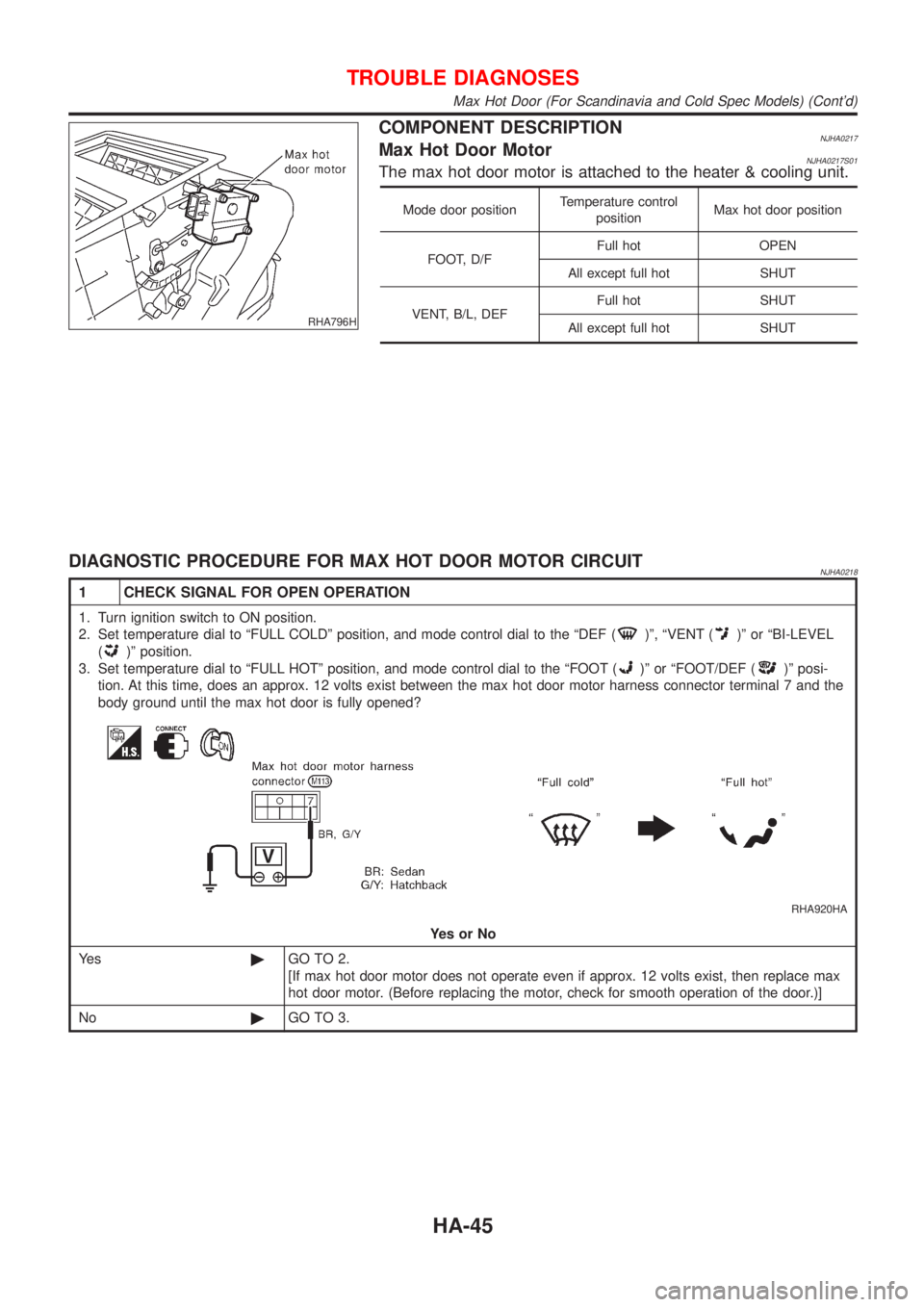
COMPONENT DESCRIPTIONNJHA0217Max Hot Door MotorNJHA0217S01The max hot door motor is attached to the heater & cooling unit.
Mode door positionTemperature control
positionMax hot door position
FOOT, D/FFull hot OPEN
All except full hot SHUT
VENT, B/L, DEFFull hot SHUT
All except full hot SHUT
DIAGNOSTIC PROCEDURE FOR MAX HOT DOOR MOTOR CIRCUITNJHA0218
1 CHECK SIGNAL FOR OPEN OPERATION
1. Turn ignition switch to ON position.
2. Set temperature dial to ªFULL COLDº position, and mode control dial to the ªDEF (
)º, ªVENT ()º or ªBI-LEVEL
(
)º position.
3. Set temperature dial to ªFULL HOTº position, and mode control dial to the ªFOOT (
)º or ªFOOT/DEF ()º posi-
tion. At this time, does an approx. 12 volts exist between the max hot door motor harness connector terminal 7 and the
body ground until the max hot door is fully opened?
RHA920HA
YesorNo
Ye s©GO TO 2.
[If max hot door motor does not operate even if approx. 12 volts exist, then replace max
hot door motor. (Before replacing the motor, check for smooth operation of the door.)]
No©GO TO 3.
TROUBLE DIAGNOSES
Max Hot Door (For Scandinavia and Cold Spec Models) (Cont'd)
HA-45
Page 2446 of 2898

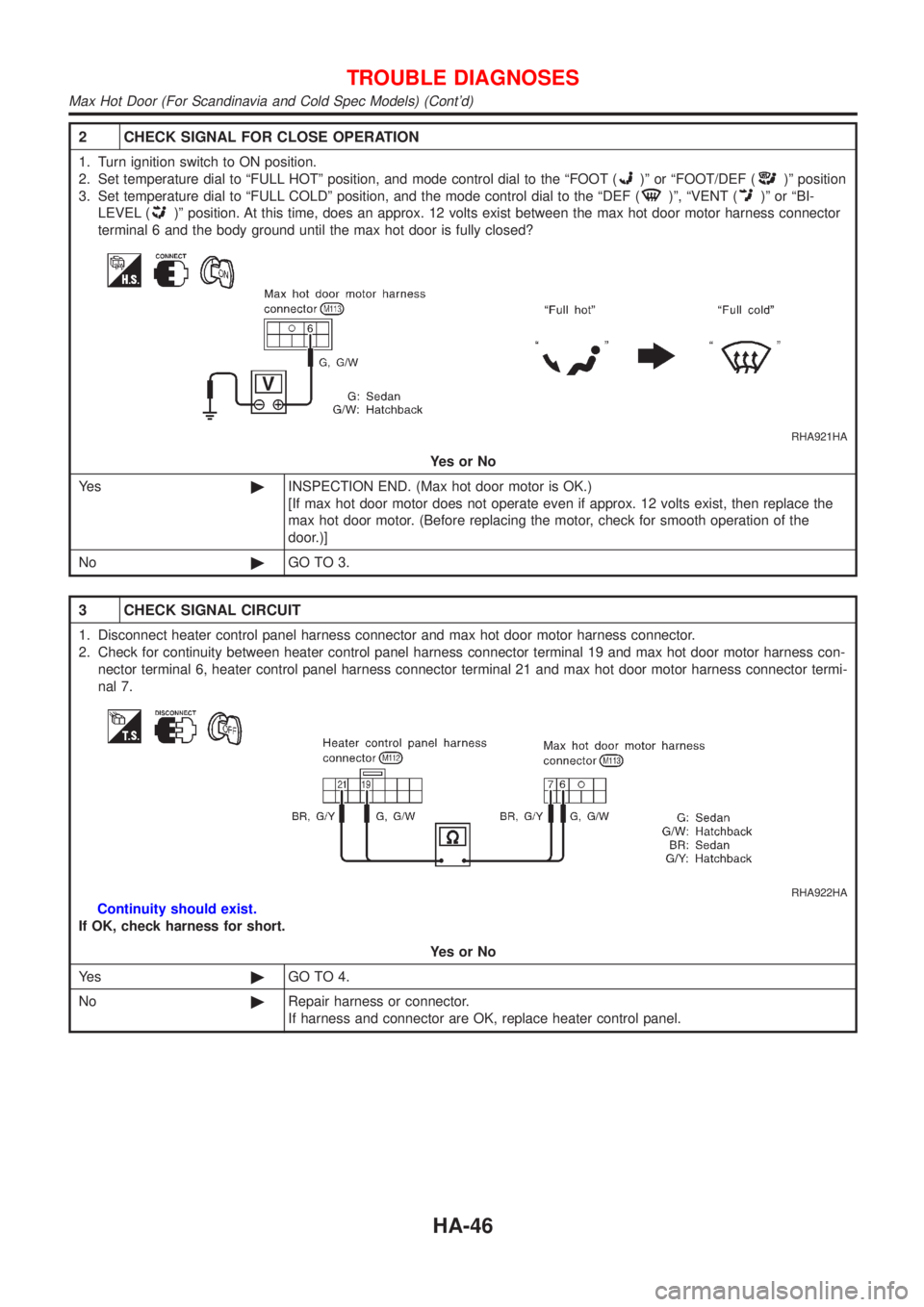
2 CHECK SIGNAL FOR CLOSE OPERATION
1. Turn ignition switch to ON position.
2. Set temperature dial to ªFULL HOTº position, and mode control dial to the ªFOOT (
)º or ªFOOT/DEF ()º position
3. Set temperature dial to ªFULL COLDº position, and the mode control dial to the ªDEF (
)º, ªVENT ()º or ªBI-
LEVEL (
)º position. At this time, does an approx. 12 volts exist between the max hot door motor harness connector
terminal 6 and the body ground until the max hot door is fully closed?
RHA921HA
YesorNo
Ye s©INSPECTION END. (Max hot door motor is OK.)
[If max hot door motor does not operate even if approx. 12 volts exist, then replace the
max hot door motor. (Before replacing the motor, check for smooth operation of the
door.)]
No©GO TO 3.
3 CHECK SIGNAL CIRCUIT
1. Disconnect heater control panel harness connector and max hot door motor harness connector.
2. Check for continuity between heater control panel harness connector terminal 19 and max hot door motor harness con-
nector terminal 6, heater control panel harness connector terminal 21 and max hot door motor harness connector termi-
nal 7.
RHA922HA
Continuity should exist.
If OK, check harness for short.
YesorNo
Ye s©GO TO 4.
No©Repair harness or connector.
If harness and connector are OK, replace heater control panel.
TROUBLE DIAGNOSES
Max Hot Door (For Scandinavia and Cold Spec Models) (Cont'd)
HA-46