2001 NISSAN ALMERA oil pressure
[x] Cancel search: oil pressurePage 391 of 2898

DISASSEMBLY=NJAT0130+Disassemble upper, inter and lower bodies.
Bolt length, number and location:
Bolt symbol A B C D E F G
Bolt length ª!º
13.5 mm
(0.531 in)58.0 mm
(2.283 in)40.0 mm
(1.575 in)66.0 mm
(2.598 in)33.0 mm
(1.299 in)78.0 mm
(3.071 in)18.0 mm
(0.709 in)
Number of bolts 6 3 6 11 2 2 1
F: Reamer bolt with nut
SAT869J
SAT083F
1. Remove bolts A, D and F, and remove oil strainer from control
valve assembly.
SAT316GA
2. Remove solenoid valve assembly and line pressure solenoid
valve from control valve assembly.
+Be careful not to lose the line pressure solenoid valve
spring.
REPAIR FOR COMPONENT PARTS
Control Valve Assembly (Cont'd)
AT-389
Page 392 of 2898

SAT317G
3. Remove O-rings from solenoid valves and terminal body.
SAT064F
4. Place upper body facedown, and remove bolts B, C and F.
SAT432D
5. Remove lower body from inter body.
SAT109D
6. Turn over lower body, and accumulator support plates.
SAT873J
7. Remove bolts E, separating plate and separating gaskets from
lower body.
8. Remove check balls, oil cooler relief valve springs and T/C
pressure holding spring from lower body.
+Be careful not to lose steel balls and relief valve springs.
REPAIR FOR COMPONENT PARTS
Control Valve Assembly (Cont'd)
AT-390
Page 394 of 2898

SAT115D
Oil StrainerNJAT0131S02+Check wire netting of oil strainer for damage.
SAT322GC
Shift Solenoid Valves A and B, Line Pressure Solenoid
Valve, Torque Converter Clutch Solenoid Valve and
Overrun Clutch Solenoid Valve
NJAT0131S03+Refer to ªResistance Checkº of each solenoid valve.
ValvesExcept for Euro-
OBDEuro-OBD
Shift solenoid valve A AT-147 AT-251
Shift solenoid vavle B AT-153 AT-257
Line pressure solenoid valve AT-182 AT-245
Torque converter clutch solenoid valve AT-164 AT-238
Overrun clutch solenoid valve AT-158 AT-273
SAT138D
Oil Cooler Relief Valve SpringNJAT0131S04+Check springs for damage or deformation.
+Measure free length and outer diameter.
Inspection standard:
Unit: mm (in)
Part No.!D
31872 31X00 17.0 (0.669) 8.0 (0.315)
SAT871J
ASSEMBLYNJAT01321. Install upper, inter and lower body.
a. Place oil circuit of upper body face up. Install steel balls in their
proper positions.
REPAIR FOR COMPONENT PARTS
Control Valve Assembly (Cont'd)
AT-392
Page 476 of 2898

Control ValvesNJAT0183CONTROL VALVE AND PLUG RETURN SPRINGSNJAT0183S01Unit: mm (in)
No. Parts Part No.* Free length Outer diameter
Upper
body
Refer to
ªControl
Valve
Upper
Bodyº,
AT-397.35 3-2 timing valve spring 31736-01X00 23.0 (0.906) 6.65 (0.2618)
19 Cooler check valve spring 31742-3AX05 28.04 (1.1039) 7.15 (0.2815)
23 Pilot valve spring 31742-3AX03 38.98 (1.5346) 8.9 (0.350)
15 1-2 accumulator valve spring 31742-3AX00 20.5 (0.807) 6.95 (0.2736)
28 1-2 accumulator piston springQG13DE
model31742-3AX08 55.26 (2.1756) 19.6 (0.772)
QG15DE,
QG16DE
&
QG18DE
models31742-3AX09 55.66 (2.1913) 19.5 (0.7677)
33 1st reducing valve spring 31742-80X05 27.0 (1.063) 7.0 (0.276)
2 Overrun clutch reducing valve spring 31742-80X06 37.5 (1.476) 7.0 (0.276)
7 Torque converter relief valve spring 31742-3AX04 33.3 (1.3110) 9.0 (0.354)
10 Torque converter clutch control valve spring 31742-3AX02 53.01 (2.0870) 6.5 (0.256)
Lower
body
Refer to
ªControl
Valve
Lower
Bodyº,
AT-401.34 Shuttle valve spring 31762-41X04 51.0 (2.0079) 5.65 (0.2224)
18 Pressure regulator valve spring 31742-80X13 45.0 (1.772) 15.0 (0.591)
23 Overrun clutch control valve spring 31762-80X00 21.7 (0.854) 7.0 (0.276)
27 Accumulator control valve spring 31742-80X02 22.0 (0.866) 6.5 (0.256)
29 Shift valve A spring 31762-80X00 21.7 (0.854) 7.0 (0.276)
2 Shift valve B spring 31762-80X00 21.7 (0.854) 7.0 (0.276)
11 Pressure modifier piston spring 31742-41X15 30.5 (1.201) 9.8 (0.386)
7 Pressure modifier valve spring 31742-80X16 32.0 (1.260) 6.9 (0.272)
Ð Oil cooler relief valve spring 31872-31X00 17.02 (0.6701) 8.0 (0.315)
Ð T/C pressure spring 31742-3AX07 9.0 (0.354) 7.3 (0.287)
*: Always check with the Parts Department for the latest parts information.
Clutch and BrakesNJAT0184REVERSE CLUTCHNJAT0184S01
Number of drive plates2
Number of driven plates2
Drive plate thickness mm (in)Standard 2.0 (0.079)
Allowable limit 1.8 (0.071)
Clearance mm (in)Standard 0.5 - 0.8 (0.020 - 0.031)
Allowable limit 1.2 (0.047)
Thickness of retaining platesThickness mm (in) Part number*
4.4 (0.173)
4.6 (0.181)
4.8 (0.189)
5.0 (0.197)
5.2 (0.205)31537-31X00
31537-31X01
31537-31X02
31537-31X03
31537-31X04
*: Always check with the Parts Department for the latest parts information.
SERVICE DATA AND SPECIFICATIONS (SDS)
Control Valves
AT-474
Page 704 of 2898
NJCL0004
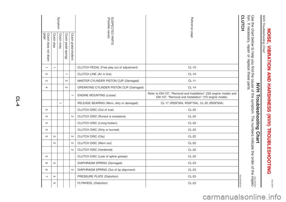
NVH Troubleshooting ChartNJCL0004S01Use the chart below to help you find the cause of the symptom. The numbers indicate the order of the inspec-
tion. If necessary, repair or replace these parts.
CLUTCHNJCL0004S0101
Reference pageCL-10
CL-10
CL-11
CL-14
Refer to EM-137, ªRemoval and Installationº (QG engine model) and
EM-137, ªRemoval and Installationº (YD engine model).
CL-17 (RS5F30A, RS5F70A), CL-20 (RS5F50A)
CL-22
CL-22
CL-22
CL-22
CL-22
CL-22
CL-22
CL-22
CL-23
CL-23
CL-23
CL-23
SUSPECTED PARTS
(Possible cause)
CLUTCH PEDAL (Free play out of adjustment)
CLUTCH LINE (Air in line)
MASTER CYLINDER PISTON CUP (Damaged)
OPERATING CYLINDER PISTON CUP (Damaged)
ENGINE MOUNTING (Loose)
RELEASE BEARING (Worn, dirty or damaged)
CLUTCH DISC (Out of true)
CLUTCH DISC (Runout is excessive)
CLUTCH DISC (Lining broken)
CLUTCH DISC (Dirty or burned)
CLUTCH DISC (Oily)
CLUTCH DISC (Worn out)
CLUTCH DISC (Hardened)
CLUTCH DISC (Lack of spline grease)
DIAPHRAGM SPRING (Damaged)
DIAPHRAGM SPRING (Out of tip alignment)
PRESSURE PLATE (Distortion)
FLYWHEEL (Distortion)
SymptomClutch grabs/chatters 1 2 2 2 2 2
Clutch pedal spongy 1 2 2
Clutch noisy 1
Clutch slips 1 2 2 3 4 5
Clutch does not disen-
gage1234 55555 5667
NOISE, VIBRATION AND HARSHNESS (NVH) TROUBLESHOOTING
NVH Troubleshooting Chart
CL-4
Page 717 of 2898
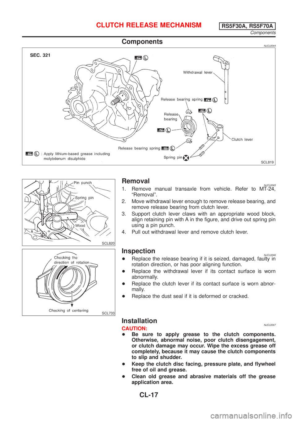
ComponentsNJCL0044
SCL819
SCL820
RemovalNJCL00451. Remove manual transaxle from vehicle. Refer to MT-24,
ªRemovalº.
2. Move withdrawal lever enough to remove release bearing, and
remove release bearing from clutch lever.
3. Support clutch lever claws with an appropriate wood block,
align retaining pin with A in the figure, and drive out spring pin
using a pin punch.
4. Pull out withdrawal lever and remove clutch lever.
SCL733
InspectionNJCL0046+Replace the release bearing if it is seized, damaged, faulty in
rotation direction, or has poor aligning function.
+Replace the withdrawal lever if its contact surface is worn
abnormally.
+Replace the clutch lever if its contact surface is worn abnor-
mally.
+Replace the dust seal if it is deformed or cracked.
InstallationNJCL0047CAUTION:
+Be sure to apply grease to the clutch components.
Otherwise, abnormal noise, poor clutch disengagement,
or clutch damage may occur. Wipe the excess grease off
completely, because it may cause the clutch components
to slip and shudder.
+Keep the clutch disc facing, pressure plate, and flywheel
free of oil and grease.
+Clean old grease and abrasive materials off the grease
application area.
CLUTCH RELEASE MECHANISMRS5F30A, RS5F70A
Components
CL-17
Page 720 of 2898

ComponentsNJCL0027
SCL842
RemovalNJCL00281. Remove manual transaxle from vehicle. Refer to MT-27,
ªRemovalº.
2. Move withdrawal lever enough to remove release bearing, and
remove release bearing from clutch withdrawal lever.
3. Remove dust cover.
4. Remove retainer spring from withdrawal lever.
SCL733
InspectionNJCL0029+Replace the release bearing if it is seized, damaged, faulty in
rotation direction, or has poor aligning function.
+Replace the withdrawal lever if its contact surface is worn
abnormally.
+Replace the dust cover if it is deformed or cracked.
InstallationNJCL00301. Apply a coat of grease to parts as instructed in the following
cautions and notes before installation.
CAUTION:
+Be sure to apply grease to the clutch components.
Otherwise, abnormal noise, poor clutch disengagement,
or clutch damage may occur. Wipe the excess grease off
completely, because it may cause the clutch components
to slip and shudder.
+Keep the clutch disc facing, pressure plate, and flywheel
free of oil and grease.
CLUTCH RELEASE MECHANISMRS5F50A
Components
CL-20
Page 730 of 2898
Diagnostic Procedure ..............................................487
Component Inspection .............................................490
EGR VOLUME CONTROL SYSTEM (WHERE
FITTED)........................................................................491
Description ...............................................................491
CONSULT-II Reference Value in Data Monitor
Mode ........................................................................492
ECM Terminals and Reference Value .....................493
Wiring Diagram ........................................................494
Diagnostic Procedure ..............................................496
Component Inspection .............................................501
EVAP CANISTER PURGE VOLUME CONTROL
SOLENOID VALVE......................................................503
Description ...............................................................503
CONSULT-II Reference Value in Data Monitor
Mode ........................................................................503
ECM Terminals and Reference Value .....................504
Wiring Diagram ........................................................505
Diagnostic Procedure ..............................................507
Component Inspection .............................................510
IDLE AIR CONTROL VALVE (IACV) - AUXILIARY
AIR CONTROL............................................................ 511
Description ............................................................... 511
CONSULT-II Reference Value in Data Monitor
Mode ........................................................................512
ECM Terminals and Reference Value .....................512
Wiring Diagram ........................................................513
Diagnostic Procedure ..............................................515
Component Inspection .............................................519
CLOSED THROTTLE POSITION SWITCH
(WHERE FITTED)........................................................520
Component Description ...........................................520
ECM Terminals and Reference Value .....................520
Wiring Diagram ........................................................521
Diagnostic Procedure ..............................................522
Component Inspection .............................................525
INTAKE VALVE TIMING CONTROL SOLENOID
VALVE..........................................................................526
Component Description ...........................................526
Operation .................................................................526
CONSULT-II Reference Value in Data Monitor
Mode ........................................................................526
ECM Terminals and Reference Value .....................526
Wiring Diagram ........................................................527
Diagnostic Procedure ..............................................529
Component Inspection .............................................531
A/T COMMUNICATION LINE......................................532
System Description ..................................................532
Wiring Diagram ........................................................533
Diagnostic Procedure ..............................................534
PARK/NEUTRAL POSITION (PNP) SWITCH............536
Component Description ...........................................536CONSULT-II Reference Value in Data Monitor
Mode ........................................................................536
ECM Terminals and Reference Value .....................536
Wiring Diagram ........................................................537
Diagnostic Procedure ..............................................538
INJECTOR...................................................................541
Component Description ...........................................541
CONSULT-II Reference Value in Data Monitor
Mode ........................................................................541
ECM Terminals and Reference Value .....................541
Wiring Diagram ........................................................542
Diagnostic Procedure ..............................................544
Component Inspection .............................................546
IGNITION SIGNAL.......................................................547
Component Description ...........................................547
CONSULT-II Reference Value in Data Monitor
Mode ........................................................................547
ECM Terminals and Reference Value .....................547
Wiring Diagram ........................................................548
Diagnostic Procedure ..............................................551
Component Inspection .............................................555
START SIGNAL...........................................................557
CONSULT-II Reference Value in Data Monitor
Mode ........................................................................557
ECM Terminals and Reference Value .....................557
Wiring Diagram ........................................................558
Diagnostic Procedure ..............................................559
FUEL PUMP.................................................................561
System Description ..................................................561
Component Description ...........................................561
CONSULT-II Reference Value in Data Monitor
Mode ........................................................................561
ECM Terminals and Reference Value .....................562
Wiring Diagram ........................................................563
Diagnostic Procedure ..............................................564
Component Inspection .............................................566
POWER STEERING OIL PRESSURE SWITCH.........567
Component Description ...........................................567
CONSULT-II Reference Value in Data Monitor
Mode ........................................................................567
ECM Terminals and Reference Value .....................567
Wiring Diagram ........................................................568
Diagnostic Procedure ..............................................569
Component Inspection .............................................570
REFRIGERANT PRESSURE SENSOR......................572
Description ...............................................................572
ECM Terminals and Reference Value .....................572
Wiring Diagram ........................................................573
Diagnostic Procedure ..............................................575
ELECTRICAL LOAD SIGNAL.....................................578
CONSULT-II Reference Value in Data Monitor
Mode ........................................................................578
CONTENTS(Cont'd)
EC-6