2001 NISSAN ALMERA service
[x] Cancel search: servicePage 2496 of 2898
Idle Air Control Valve (IACV) Ð Auxiliary Air
Control (AAC) Valve
INSPECTIONNJHA0199+Refer to EC-376 (QG), ªSystem Descriptionº.
RHA680H
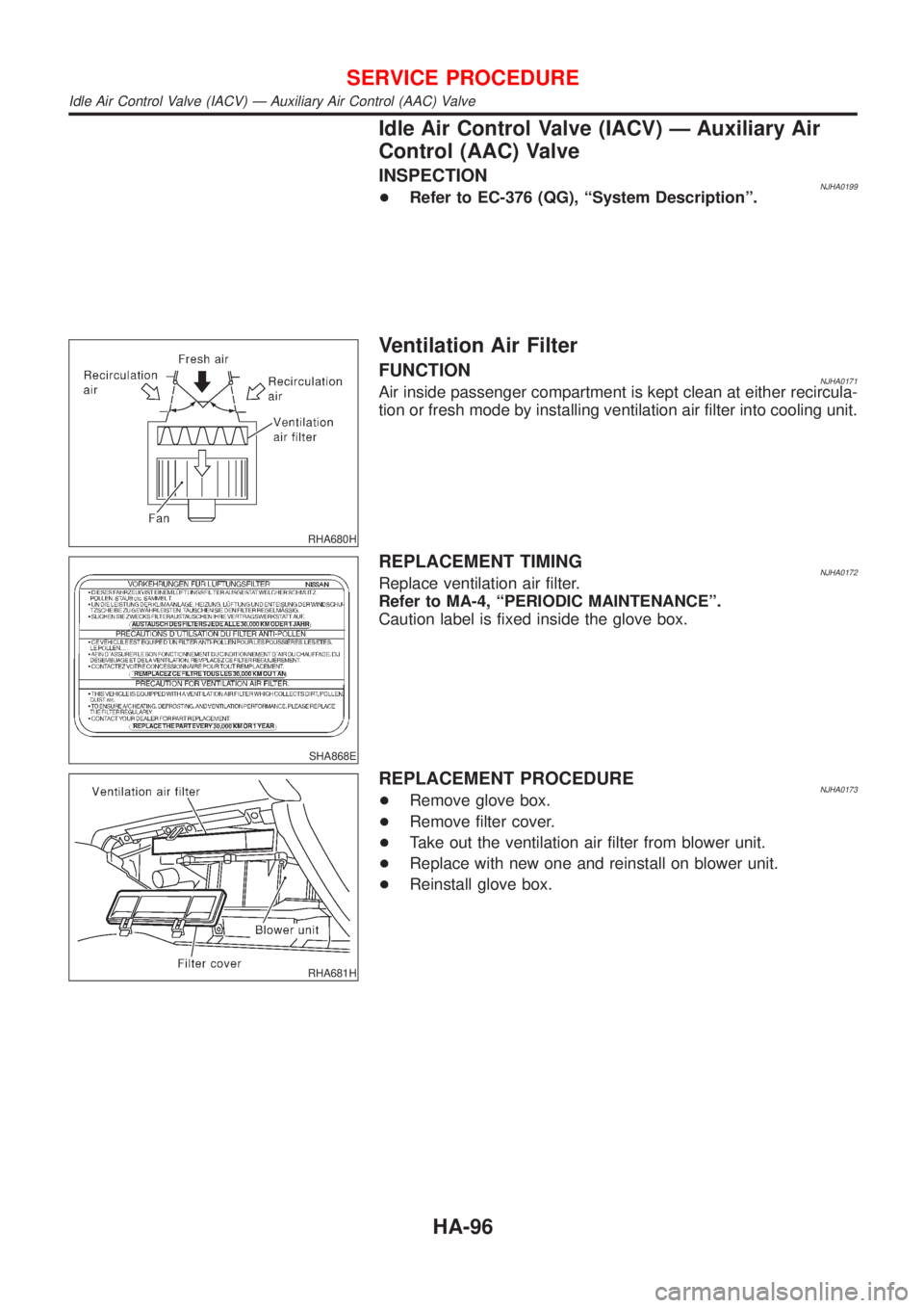
Ventilation Air Filter
FUNCTIONNJHA0171Air inside passenger compartment is kept clean at either recircula-
tion or fresh mode by installing ventilation air filter into cooling unit.
SHA868E
REPLACEMENT TIMINGNJHA0172Replace ventilation air filter.
Refer to MA-4, ªPERIODIC MAINTENANCEº.
Caution label is fixed inside the glove box.
RHA681H
REPLACEMENT PROCEDURENJHA0173+Remove glove box.
+Remove filter cover.
+Take out the ventilation air filter from blower unit.
+Replace with new one and reinstall on blower unit.
+Reinstall glove box.
SERVICE PROCEDURE
Idle Air Control Valve (IACV) Ð Auxiliary Air Control (AAC) Valve
HA-96
Page 2497 of 2898
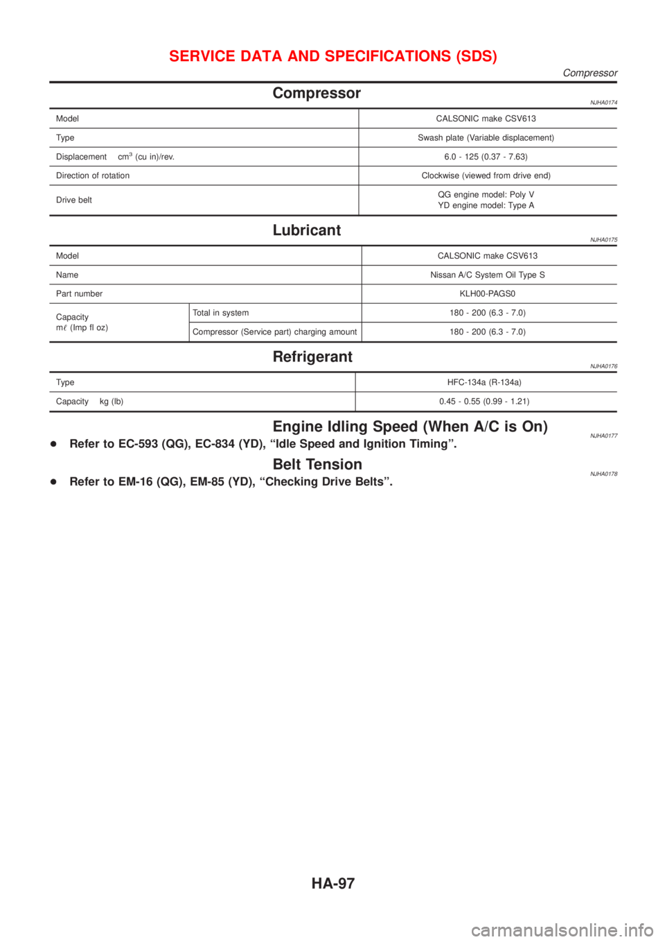
CompressorNJHA0174
ModelCALSONIC make CSV613
TypeSwash plate (Variable displacement)
Displacement cm
3(cu in)/rev.6.0 - 125 (0.37 - 7.63)
Direction of rotationClockwise (viewed from drive end)
Drive beltQG engine model: Poly V
YD engine model: Type A
LubricantNJHA0175
ModelCALSONIC make CSV613
NameNissan A/C System Oil Type S
Part numberKLH00-PAGS0
Capacity
m!(Imp fl oz)Total in system 180 - 200 (6.3 - 7.0)
Compressor (Service part) charging amount 180 - 200 (6.3 - 7.0)
RefrigerantNJHA0176
TypeHFC-134a (R-134a)
Capacity kg (lb)0.45 - 0.55 (0.99 - 1.21)
Engine Idling Speed (When A/C is On)NJHA0177+Refer to EC-593 (QG), EC-834 (YD), ªIdle Speed and Ignition Timingº.
Belt TensionNJHA0178+Refer to EM-16 (QG), EM-85 (YD), ªChecking Drive Beltsº.
SERVICE DATA AND SPECIFICATIONS (SDS)
Compressor
HA-97
Page 2498 of 2898

SERVICE DATA AND SPECIFICATIONS (SDS)
Belt Tension (Cont'd)
HA-98
Page 2500 of 2898
A
A/C HFC134a (R134a) system precaution . HA-2
A/C HFC134a (R134a) system service
procedure .............................................. HA-78
A/C HFC134a (R134a) system service
tools ....................................................... HA-11
A/C HFC134a system service equip-
ment precaution ....................................... HA-6
A/C air flow ............................................... HA-20
A/C component layout .............................. HA-18
A/C compressor clutch removal and
installation .............................................. HA-83
A/C compressor precaution ........................ HA-5
A/C compressor special service tool .......... HA-9
A/C control linkage adjustment
(manual A/C) ......................................... HA-41
A/C control operation (manual A/C) .......... HA-19
A/C diagnostic work flow
(manual A/C) ........................................ HA-33
A/C harness layout (manual A/C) ............. HA-22
A/C lubricant (R134a) ............................... HA-80
A/C operational check ............................... HA-34
A/C performance chart .............................. HA-71
A/C performance test diagnoses .............. HA-69
A/C relay ................................................... HA-66
A/C service data specification .................. HA-97
A/C switch ................................................. HA-67
A/C, M - Wiring diagram ........................... HA-27
A/CCUT - Wiring diagram ....................... EC-830
A/T - Wiring diagram - AT - 1ST .............. AT-207
A/T - Wiring diagram - AT - 2ND ............. AT-214
A/T - Wiring diagram - AT - 3RD ............. AT-220
A/T - Wiring diagram - AT - 4TH .............. AT-227
A/T - Wiring diagram - AT - BA/FTS ....... AT-167,
276
A/T - Wiring diagram - AT - ENG SS ...... AT-173,
201
A/T - Wiring diagram - AT - FTS .............. AT-191
A/T - Wiring diagram - AT - LPSV ... AT-178, 241
A/T - Wiring diagram - AT - MAIN ........... AT-123
A/T - Wiring diagram - AT -
NONDTC .............................................. AT-292
A/T - Wiring diagram - AT -
OVRCSV ...................................... AT-155, 270
A/T - Wiring diagram - AT - PNP/SW ...... AT-185
A/T - Wiring diagram - AT - SSV/A .. AT-144, 248
A/T - Wiring diagram - AT - SSV/B .. AT-150, 254
A/T - Wiring diagram - AT - TCV ..... AT-161, 235
A/T - Wiring diagram - AT - TPS ..... AT-136, 261
A/T - Wiring diagram - AT - VSS/AT ....... AT-128,
197
A/T - Wiring diagram - AT -
VSSMTR ...................................... AT-132, 283
A/T IND - Wiring diagram ........................ EL-195
A/T control ............................................... EC-532
A/T diagnosis communication line .......... EC-434
A/T fluid temperature sensor ................... AT-194A/T shift lock system - Wiring
diagram ................................................ AT-344
A/T shift lock system ................................ AT-343
A/T trouble diagnoses .......................... AT-69, 74
AAC/V - Wiring diagram ................. EC-378, 513
ABS (anti-lock brake system) ................... BR-49
ABS - Wiring diagram ............................... BR-54
ABS sensor rotor ....................................... AX-24
APS - Wiring diagram ............................. EC-685
ATDIAG - Wiring diagram ............... EC-435, 533
Accelerator control system .................... FE-3, 19
Accelerator position sensor .................... EC-685
Air bag disposal ........................................ RS-40
Air bag precautions ...................................... GI-3
Air bag ....................................................... RS-20
Air bleeding (hydraulic clutch) ................... CL-10
Air bleeding for brake system ..................... BR-9
Air conditioner cut control ................. EC-35, 612
Air flow meter - See Mass air flow
sensor .......................................... EC-187, 673
Air mix door control linkage
adjustment ............................................. HA-43
Air spoiler, rear .......................................... BT-47
Alternator ................................................... SC-31
Angular tightening application .............. EM-4, 77
Antenna - See Power antenna ................ EL-282
Anti-lock brake system - Wiring
diagram .................................................. BR-54
Audio and A/C control removal and
installation - See Instrument panel ........ BT-25
Audio ........................................................ EL-258
Automatic transaxle number ...................... GI-41
Auxiliary air control (AAC) valve ..... EC-376, 511
B
Back-up lamp switch (M/T) ....................... MT-21
Back-up lamp ............................................. EL-87
Ball joint (front) .......................................... SU-13
Basic inspection ...................... EC-100, 128, 641
Battery ......................................................... SC-3
Baulk ring (M/T) ............................ MT-31, 55, 93
Blower motor ............................................. HA-54
Blower resistor .......................................... HA-54
Board-on lift ................................................ GI-44
Body alignment .......................................... BT-77
Brake booster ............................................ BR-20
Brake fluid change ...................................... BR-8
Brake fluid level and line check .................. BR-8
Brake hydraulic line .................................. BR-10
Brake master cylinder ............................... BR-14
Brake pedal ............................................... BR-12
Bulb specifications ................................... EL-574
Bumper, front .............................................. BT-7
Bumper, rear .............................................. BT-10
ALPHABETICAL INDEX
IDX-2
Page 2501 of 2898
C
CHARGE - Wiring diagram ....................... SC-27
CHIME - Wiring diagram ................. EL-199, 207
CIGAR - Wiring diagram ................. EL-236, 237
CKPS - Wiring diagram .......... EC-330, 485, 695
CMPS - Wiring diagram .......................... EC-337
CONSULT for ABS .................................... BR-65
CONSULT for engine ........................ EC-83, 632
COOL/F - Wiring diagram ............... EC-409, 730
Camshaft inspection ......................... EM-37, 123
Camshaft position sensor (CMPS) ......... EC-335
Camshaft position sensor (PHASE) ........ EC-335
Canister - See EVAP canister ................... EC-36
Charging system ....................................... SC-26
Cigarette lighter ....................................... EL-236
Circuit breaker ........................................... EL-38
Closed throttle position switch ....... EC-385, 520
Clutch cover .............................................. CL-22
Clutch disc ................................................. CL-22
Clutch master cylinder ............................... CL-11
Clutch operating cylinder ........................... CL-14
Clutch pedal .............................................. CL-10
Clutch release bearing ........................ CL-17, 20
Clutch release mechanism .................. CL-17, 20
Clutch withdrawal lever ....................... CL-17, 20
Coil spring (front) ........................................ SU-9
Coil spring (rear) ....................................... SU-21
Collision diagnosis .................................... RS-85
Combination lamp, rear, removal and
installation .............................................. BT-47
Combination meter removal and instal-
lation - See Instrument panel ................ BT-25
Combination meter .................................. EL-144
Combination switch ................................... EL-56
Compression pressure ............................. EM-83
Compressor clutch removal and
installation .............................................. HA-83
Compressor precaution ............................... HA-5
Compressor special service tool ................. HA-9
Connecting rod bearing clearance ... EM-60, 151
Connecting rod bushing clearance ... EM-61, 153
Connecting rod ................................. EM-57, 146
Console box - See Instrument panel ......... BT-25
Control lever (M/T) .................................... MT-29
Control valve (A/T) ................................... AT-388
Converter housing installation ................. AT-355
Coolant mixture ratio ................................ MA-18
Cooling circuit (engine) ....................... LC-12, 37
Cooling fan control system .................. LC-17, 43
Cooling fan control .......................... EC-406, 730
Cooling fan motor ................................... EC-417
Cooling fan relay ..................................... EC-416
Coupling sleeve (M/T) .................. MT-31, 55, 93
Crankcase emission control system -
See Positive crankcase ventilation ...... EC-39,
613
Crankcase ventilation system - See
Positive crankcase ventilation ....... EC-39, 613
Crankshaft position sensor (OBD) .. EC-328, 484Crankshaft position sensor (POS) .. EC-328, 484
Crankshaft position sensor (TDC) .......... EC-695
Crankshaft ........................................ EM-59, 148
Cylinder block ................................... EM-54, 140
Cylinder head .................................... EM-34, 119
D
DEF - Wiring diagram ...................... EL-242, 250
DTC work support ..................................... EC-92
Data link connector for Consult ........ EC-40, 632
Daytime light system ................................. EL-67
Detonation sensor - See Knock
sensor .................................................. EC-324
Diagnosis sensor unit ............................... RS-26
Diagnostic trouble code (DTC) for
OBD system .................... EC-10, 72, 596, 627
Diagnostic trouble code (DTC) inspec-
tion priority chart .................................. EC-153
Differential gear (FF A/T) ......................... AT-442
Differential gear (FF M/T) ...... MT-31, 44, 55, 93,
107
Dimensions ................................................. GI-43
Dome light - See Interior lamp ................ EL-115
Door glass ................................................. BT-17
Door lock ................................................... BT-21
Door mirror ................................................ BT-75
Door trim .................................................... BT-39
Door, front .................................................. BT-16
Door, rear ................................................... BT-16
Drive plate runout ..................................... EM-62
Drive shaft (front) ...................................... AX-10
Dropping resistor (A/T) .................... AT-182, 245
Dual pressure switch ................................ HA-13
E
ECCS-D control module ........ EC-659, 714, 792,
794, 799, 801
ECM input/output signal ................. EC-164, 659
ECTS - Wiring diagram ................... EC-203, 680
EGR control valve ................................... EC-432
EGR temperature sensor ........................ EC-418
EGR volume control valve ...................... EC-815
EGR/TS - Wiring diagram ....................... EC-421
EGRC1 - Wiring diagram ....... EC-347, 429, 494,
817
EVAP canister purge volume control
solenoid valve ........................................ EC-37
EVAP canister purge volume control
valve ............................................ EC-364, 503
EVAP canister ........................................... EC-37
Electric sunroof ........................................ EL-292
Electrical diagnoses ................................... GI-21
Electrical ignition system .......................... EC-34
Electrical load signal circuit ..................... EC-578
Electrical unit ........................................... EL-581
Electrical units location ............................ EL-517
ALPHABETICAL INDEX
IDX-3
Page 2502 of 2898
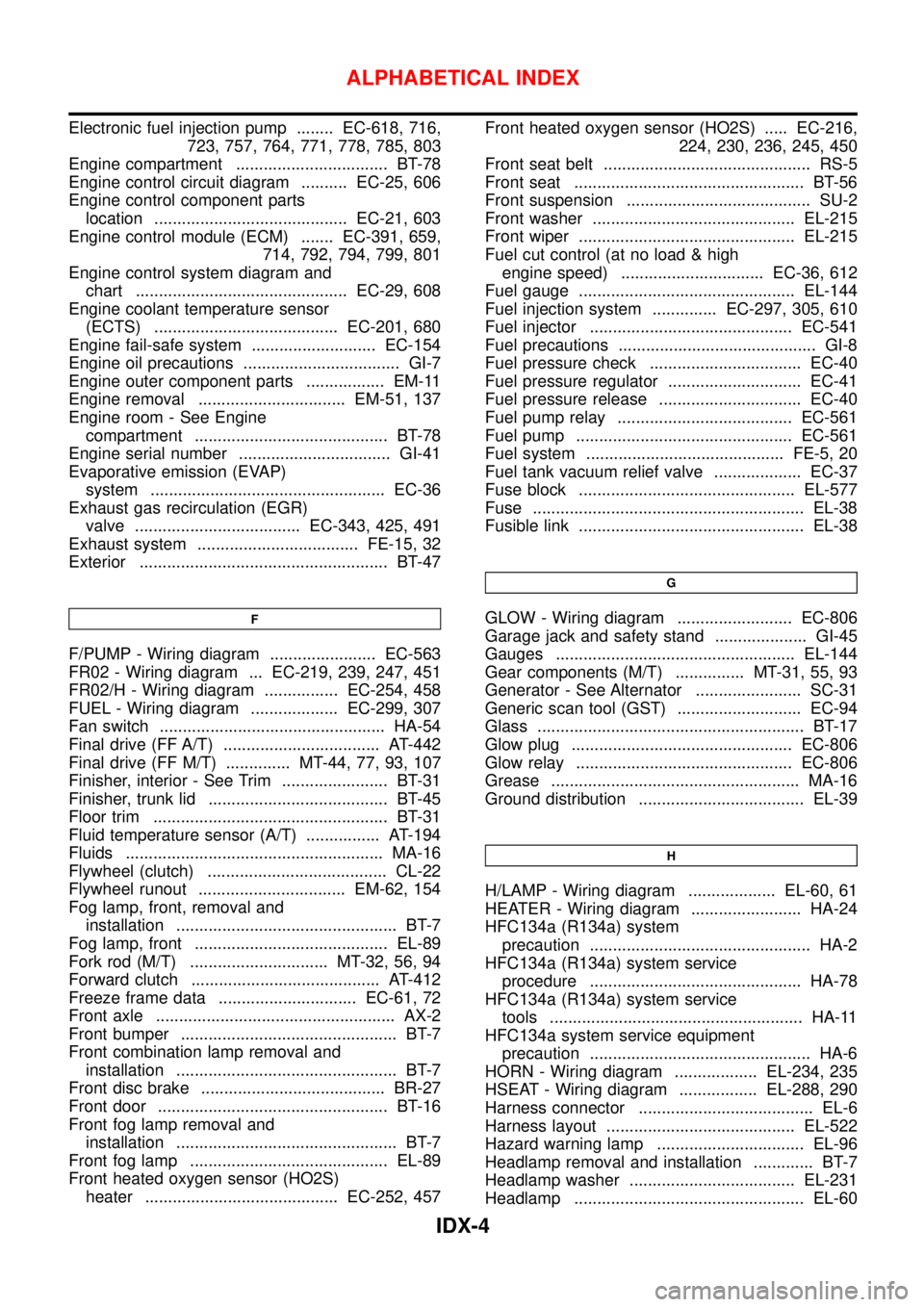
Electronic fuel injection pump ........ EC-618, 716,
723, 757, 764, 771, 778, 785, 803
Engine compartment ................................. BT-78
Engine control circuit diagram .......... EC-25, 606
Engine control component parts
location .......................................... EC-21, 603
Engine control module (ECM) ....... EC-391, 659,
714, 792, 794, 799, 801
Engine control system diagram and
chart .............................................. EC-29, 608
Engine coolant temperature sensor
(ECTS) ........................................ EC-201, 680
Engine fail-safe system ........................... EC-154
Engine oil precautions .................................. GI-7
Engine outer component parts ................. EM-11
Engine removal ................................ EM-51, 137
Engine room - See Engine
compartment .......................................... BT-78
Engine serial number ................................. GI-41
Evaporative emission (EVAP)
system ................................................... EC-36
Exhaust gas recirculation (EGR)
valve .................................... EC-343, 425, 491
Exhaust system ................................... FE-15, 32
Exterior ...................................................... BT-47
F
F/PUMP - Wiring diagram ....................... EC-563
FR02 - Wiring diagram ... EC-219, 239, 247, 451
FR02/H - Wiring diagram ................ EC-254, 458
FUEL - Wiring diagram ................... EC-299, 307
Fan switch ................................................. HA-54
Final drive (FF A/T) .................................. AT-442
Final drive (FF M/T) .............. MT-44, 77, 93, 107
Finisher, interior - See Trim ....................... BT-31
Finisher, trunk lid ....................................... BT-45
Floor trim ................................................... BT-31
Fluid temperature sensor (A/T) ................ AT-194
Fluids ........................................................ MA-16
Flywheel (clutch) ....................................... CL-22
Flywheel runout ................................ EM-62, 154
Fog lamp, front, removal and
installation ................................................ BT-7
Fog lamp, front .......................................... EL-89
Fork rod (M/T) .............................. MT-32, 56, 94
Forward clutch ......................................... AT-412
Freeze frame data .............................. EC-61, 72
Front axle .................................................... AX-2
Front bumper ............................................... BT-7
Front combination lamp removal and
installation ................................................ BT-7
Front disc brake ........................................ BR-27
Front door .................................................. BT-16
Front fog lamp removal and
installation ................................................ BT-7
Front fog lamp ........................................... EL-89
Front heated oxygen sensor (HO2S)
heater .......................................... EC-252, 457Front heated oxygen sensor (HO2S) ..... EC-216,
224, 230, 236, 245, 450
Front seat belt ............................................. RS-5
Front seat .................................................. BT-56
Front suspension ........................................ SU-2
Front washer ............................................ EL-215
Front wiper ............................................... EL-215
Fuel cut control (at no load & high
engine speed) ............................... EC-36, 612
Fuel gauge ............................................... EL-144
Fuel injection system .............. EC-297, 305, 610
Fuel injector ............................................ EC-541
Fuel precautions ........................................... GI-8
Fuel pressure check ................................. EC-40
Fuel pressure regulator ............................. EC-41
Fuel pressure release ............................... EC-40
Fuel pump relay ...................................... EC-561
Fuel pump ............................................... EC-561
Fuel system ........................................... FE-5, 20
Fuel tank vacuum relief valve ................... EC-37
Fuse block ............................................... EL-577
Fuse ........................................................... EL-38
Fusible link ................................................. EL-38
G
GLOW - Wiring diagram ......................... EC-806
Garage jack and safety stand .................... GI-45
Gauges .................................................... EL-144
Gear components (M/T) ............... MT-31, 55, 93
Generator - See Alternator ....................... SC-31
Generic scan tool (GST) ........................... EC-94
Glass .......................................................... BT-17
Glow plug ................................................ EC-806
Glow relay ............................................... EC-806
Grease ...................................................... MA-16
Ground distribution .................................... EL-39
H
H/LAMP - Wiring diagram ................... EL-60, 61
HEATER - Wiring diagram ........................ HA-24
HFC134a (R134a) system
precaution ................................................ HA-2
HFC134a (R134a) system service
procedure .............................................. HA-78
HFC134a (R134a) system service
tools ....................................................... HA-11
HFC134a system service equipment
precaution ................................................ HA-6
HORN - Wiring diagram .................. EL-234, 235
HSEAT - Wiring diagram ................. EL-288, 290
Harness connector ...................................... EL-6
Harness layout ......................................... EL-522
Hazard warning lamp ................................ EL-96
Headlamp removal and installation ............. BT-7
Headlamp washer .................................... EL-231
Headlamp .................................................. EL-60
ALPHABETICAL INDEX
IDX-4
Page 2507 of 2898
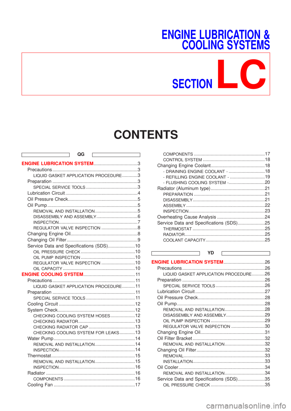
ENGINE LUBRICATION &
COOLING SYSTEMS
SECTION
LC
CONTENTS
QG
ENGINE LUBRICATION SYSTEM..................................3
Precautions ..................................................................3
LIQUID GASKET APPLICATION PROCEDURE............3
Preparation ..................................................................3
SPECIAL SERVICE TOOLS........................................3
Lubrication Circuit ........................................................4
Oil Pressure Check......................................................5
Oil Pump ......................................................................5
REMOVAL AND INSTALLATION.................................5
DISASSEMBLY AND ASSEMBLY................................6
INSPECTION.............................................................7
REGULATOR VALVE INSPECTION............................8
Changing Engine Oil....................................................8
Changing Oil Filter .......................................................9
Service Data and Specifications (SDS).....................10
OIL PRESSURE CHECK..........................................10
OIL PUMP INSPECTION..........................................10
REGULATOR VALVE INSPECTION..........................10
OIL CAPACITY........................................................10
ENGINE COOLING SYSTEM........................................ 11
Precautions ................................................................ 11
LIQUID GASKET APPLICATION PROCEDURE.......... 11
Preparation ................................................................ 11
SPECIAL SERVICE TOOLS...................................... 11
Cooling Circuit ...........................................................12
System Check............................................................12
CHECKING COOLING SYSTEM HOSES...................12
CHECKING RADIATOR............................................13
CHECKING RADIATOR CAP....................................13
CHECKING COOLING SYSTEM FOR LEAKS............13
Water Pump ...............................................................14
REMOVAL AND INSTALLATION...............................14
INSPECTION...........................................................14
Thermostat .................................................................15
REMOVAL AND INSTALLATION...............................15
INSPECTION...........................................................16
Radiator .....................................................................16
COMPONENTS.......................................................16
Cooling Fan ...............................................................17
COMPONENTS.......................................................17
CONTROL SYSTEM................................................18
Changing Engine Coolant..........................................18
- DRAINING ENGINE COOLANT -............................18
- REFILLING ENGINE COOLANT -...........................19
- FLUSHING COOLING SYSTEM -............................20
Radiator (Aluminum type) ..........................................21
PREPARATION.......................................................21
DISASSEMBLY........................................................21
ASSEMBLY.............................................................22
INSPECTION...........................................................23
Overheating Cause Analysis .....................................24
Service Data and Specifications (SDS).....................25
THERMOSTAT........................................................25
RADIATOR..............................................................25
COOLANT CAPACITY..............................................25
YD
ENGINE LUBRICATION SYSTEM................................26
Precautions ................................................................26
LIQUID GASKET APPLICATION PROCEDURE..........26
Preparation ................................................................26
SPECIAL SERVICE TOOLS......................................26
Lubrication Circuit ......................................................27
Oil Pressure Check....................................................28
Oil Pump ....................................................................28
REMOVAL AND INSTALLATION...............................28
DISASSEMBLY AND ASSEMBLY..............................29
OIL PUMP INSPECTION..........................................29
REGULATOR VALVE INSPECTION..........................30
Changing Engine Oil..................................................31
Oil Filter Bracket ........................................................32
REMOVAL AND INSTALLATION...............................32
Changing Oil Filter .....................................................32
REMOVAL...............................................................33
INSTALLATION........................................................33
Oil Cooler ...................................................................34
REMOVAL AND INSTALLATION...............................34
Service Data and Specifications (SDS).....................35
OIL PRESSURE CHECK..........................................35
Page 2508 of 2898
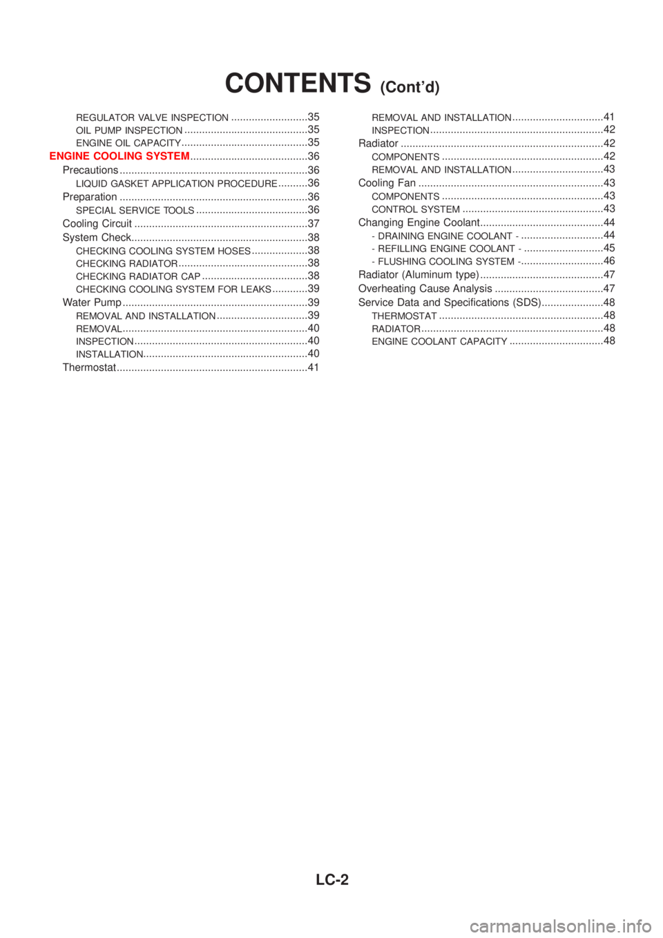
REGULATOR VALVE INSPECTION..........................35
OIL PUMP INSPECTION..........................................35
ENGINE OIL CAPACITY...........................................35
ENGINE COOLING SYSTEM........................................36
Precautions ................................................................36
LIQUID GASKET APPLICATION PROCEDURE..........36
Preparation ................................................................36
SPECIAL SERVICE TOOLS......................................36
Cooling Circuit ...........................................................37
System Check............................................................38
CHECKING COOLING SYSTEM HOSES...................38
CHECKING RADIATOR............................................38
CHECKING RADIATOR CAP....................................38
CHECKING COOLING SYSTEM FOR LEAKS............39
Water Pump ...............................................................39
REMOVAL AND INSTALLATION...............................39
REMOVAL...............................................................40
INSPECTION...........................................................40
INSTALLATION........................................................40
Thermostat .................................................................41
REMOVAL AND INSTALLATION...............................41
INSPECTION...........................................................42
Radiator .....................................................................42
COMPONENTS.......................................................42
REMOVAL AND INSTALLATION...............................43
Cooling Fan ...............................................................43
COMPONENTS.......................................................43
CONTROL SYSTEM................................................43
Changing Engine Coolant..........................................44
- DRAINING ENGINE COOLANT -............................44
- REFILLING ENGINE COOLANT -...........................45
- FLUSHING COOLING SYSTEM -............................46
Radiator (Aluminum type) ..........................................47
Overheating Cause Analysis .....................................47
Service Data and Specifications (SDS).....................48
THERMOSTAT........................................................48
RADIATOR..............................................................48
ENGINE COOLANT CAPACITY................................48
CONTENTS(Cont'd)
LC-2