Page 2480 of 2898

Maintenance of Lubricant Quantity in
Compressor
NJHA0160The lubricant in the compressor circulates through the system with
the refrigerant. Add lubricant to compressor when replacing any
component or after a large gas leakage occurred. It is important to
maintain the specified amount.
If lubricant quantity is not maintained properly, the following mal-
functions may result:
+Lack of lubricant: May lead to a seized compressor
+Excessive lubricant: Inadequate cooling (thermal exchange
interference)
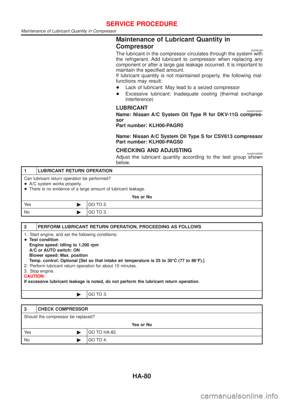
LUBRICANTNJHA0160S01Name: Nissan A/C System Oil Type R for DKV-11G compres-
sor
Part number: KLH00-PAGR0
Name: Nissan A/C System Oil Type S for CSV613 compressor
Part number: KLH00-PAGS0
CHECKING AND ADJUSTINGNJHA0160S02Adjust the lubricant quantity according to the test group shown
below.
1 LUBRICANT RETURN OPERATION
Can lubricant return operation be performed?
+A/C system works properly.
+There is no evidence of a large amount of lubricant leakage.
YesorNo
Ye s©GO TO 2.
No©GO TO 3.
2 PERFORM LUBRICANT RETURN OPERATION, PROCEEDING AS FOLLOWS
1. Start engine, and set the following conditions:
+Test condition
Engine speed: Idling to 1,200 rpm
A/C or AUTO switch: ON
Blower speed: Max. position
Temp. control: Optional [Set so that intake air temperature is 25 to 30ÉC (77 to 86ÉF).]
2. Perform lubricant return operation for about 10 minutes.
3. Stop engine.
CAUTION:
If excessive lubricant leakage is noted, do not perform the lubricant return operation.
©GO TO 3.
3 CHECK COMPRESSOR
Should the compressor be replaced?
YesorNo
Ye s©GO TO HA-82.
No©GO TO 4.
SERVICE PROCEDURE
Maintenance of Lubricant Quantity in Compressor
HA-80
Page 2481 of 2898
4 CHECK ANY PART
Is there any part to be replaced? (Evaporator, condenser, liquid tank or in case there is evidence of a large amount of
lubricant leakage.)
YesorNo
Ye s©GO TO HA-82.
No©Carry out the A/C performance test.
SERVICE PROCEDURE
Maintenance of Lubricant Quantity in Compressor (Cont'd)
HA-81
Page 2482 of 2898

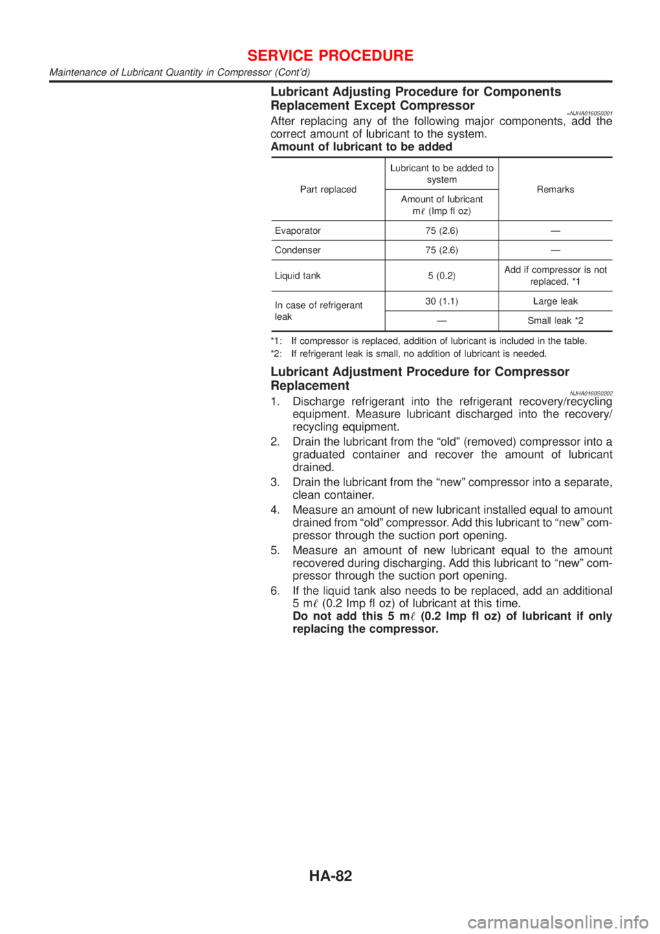
Lubricant Adjusting Procedure for Components
Replacement Except Compressor
=NJHA0160S0201After replacing any of the following major components, add the
correct amount of lubricant to the system.
Amount of lubricant to be added
Part replacedLubricant to be added to
system
Remarks
Amount of lubricant
m!(Imp fl oz)
Evaporator 75 (2.6) Ð
Condenser 75 (2.6) Ð
Liquid tank 5 (0.2)Add if compressor is not
replaced. *1
In case of refrigerant
leak30 (1.1) Large leak
Ð Small leak *2
*1: If compressor is replaced, addition of lubricant is included in the table.
*2: If refrigerant leak is small, no addition of lubricant is needed.
Lubricant Adjustment Procedure for Compressor
Replacement
NJHA0160S02021. Discharge refrigerant into the refrigerant recovery/recycling
equipment. Measure lubricant discharged into the recovery/
recycling equipment.
2. Drain the lubricant from the ªoldº (removed) compressor into a
graduated container and recover the amount of lubricant
drained.
3. Drain the lubricant from the ªnewº compressor into a separate,
clean container.
4. Measure an amount of new lubricant installed equal to amount
drained from ªoldº compressor. Add this lubricant to ªnewº com-
pressor through the suction port opening.
5. Measure an amount of new lubricant equal to the amount
recovered during discharging. Add this lubricant to ªnewº com-
pressor through the suction port opening.
6. If the liquid tank also needs to be replaced, add an additional
5m!(0.2 Imp fl oz) of lubricant at this time.
Do not add this 5 m!(0.2 Imp fl oz) of lubricant if only
replacing the compressor.
SERVICE PROCEDURE
Maintenance of Lubricant Quantity in Compressor (Cont'd)
HA-82
Page 2483 of 2898
RHA065DH
Compressor
REMOVAL AND INSTALLATIONNJHA0161
RHA803H
SERVICE PROCEDURE
Maintenance of Lubricant Quantity in Compressor (Cont'd)
HA-83
Page 2484 of 2898
RHA804H
Compressor Clutch Ð CSV613 (CALSONIC
make)
OVERHAULNJHA0211
RHA805H
SERVICE PROCEDURE
Compressor (Cont'd)
HA-84
Page 2485 of 2898
RHA136E
REMOVALNJHA0212+When removing center bolt, hold clutch disc with clutch disc
wrench.
RHA399FA
RHA124FA
+Remove the clutch disc using the clutch disc puller.
Insert the holder's three pins into the holes in the clutch disc.
Rotate the holder clockwise to hook it onto the plate. Then,
tighten the center bolt to remove the clutch disc.
After removing the clutch disc, remove the shims from either
the drive shaft or the clutch disc.
RHA138E
+Remove the snap ring using external snap ring pliers.
RHA139E
+Pulley removal
Position the center pulley puller on the end of the drive shaft,
and remove the pulley assembly using any commercially avail-
able pulley puller.
To prevent the pulley groove from being deformed, the
puller claws should be positioned onto the edge of the
pulley assembly.
SERVICE PROCEDURE
Compressor Clutch Ð CSV613 (CALSONIC make) (Cont'd)
HA-85
Page 2486 of 2898
RHA806H
+Remove the connector from the connector bracket.
RHA145E
+Remove the snap ring using external snap ring pliers.
RHA126F
INSPECTIONNJHA0213Clutch DiscNJHA0213S01If the contact surface shows signs of damage due to excessive
heat, replace clutch disc and pulley.
PulleyNJHA0213S02Check the appearance of the pulley assembly. If the contact sur-
face of pulley shows signs of excessive grooving, replace clutch
disc and pulley. The contact surfaces of the pulley assembly should
be cleaned with a suitable solvent before reinstallation.
CoilNJHA0213S03Check coil for loose connection or cracked insulation.
RHA142E
INSTALLATIONNJHA0214+Install the field coil.
Be sure to align the coil's pin with the hole in the com-
pressor's front head.
+Install the field coil harness clip using a screwdriver.
SERVICE PROCEDURE
Compressor Clutch Ð CSV613 (CALSONIC make) (Cont'd)
HA-86
Page 2487 of 2898
RHA143E
+Install the pulley assembly using the installer and a hand
press, and then install the snap ring using snap ring pliers.
RHA127F
+Install the clutch disc on the drive shaft, together with the
original shim(s). Press the clutch disc down by hand.
RHA086E
+Using the holder to prevent clutch disc rotation, tighten the bolt
to 14 N´m (1.4 kg-m, 10 ft-lb) torque.
After tightening the bolt, check that the pulley rotates
smoothly.
RHA087E
+Check clearance around the entire periphery of clutch disc.
Disc-to-pulley clearance:
0.3 - 0.6 mm (0.012 - 0.024 in)
If the specified clearance is not obtained, replace adjusting
spacer and readjust.
Break-in OperationNJHA0214S01When replacing compressor clutch assembly, always carry out the
break-in operation. This is done by engaging and disengaging the
clutch about thirty times. Break-in operation raises the level of
transmitted torque.
SERVICE PROCEDURE
Compressor Clutch Ð CSV613 (CALSONIC make) (Cont'd)
HA-87