Page 1276 of 2898
4 CHECK IGNITION COIL POWER SUPPLY CIRCUIT-II
1. Turn ignition switch OFF.
2. Disconnect condenser harness connector.
JEF121Y
3. Turn ignition switch ON.
4. Check voltage between condenser terminal 1 and ground with CONSULT-II or tester.
SEF367X
OK or NG
OK©GO TO 10.
NG©GO TO 5.
5 CHECK IGNITION COIL POWER SUPPLY CIRCUIT-III
1. Turn ignition switch OFF.
2. Disconnect ECM relay. (For ECM relay location, refer to ªEngine Control Component Parts Locationº.)
3. Check harness continuity between ECM relay terminal 7 and condenser terminal 1. Refer to Wiring Diagram.
Continuity should exist.
4. Also check harness for short to ground and short to power.
OK or NG
OK©GO TO 7.
NG©GO TO 6.
6 DETECT MALFUNCTIONING PART
Check the harness for open or short between ECM relay and condenser.
©Repair open circuit or short to ground or short to power in harness or connectors.
IGNITION SIGNALQG
Diagnostic Procedure (Cont'd)
EC-552
Page 1277 of 2898

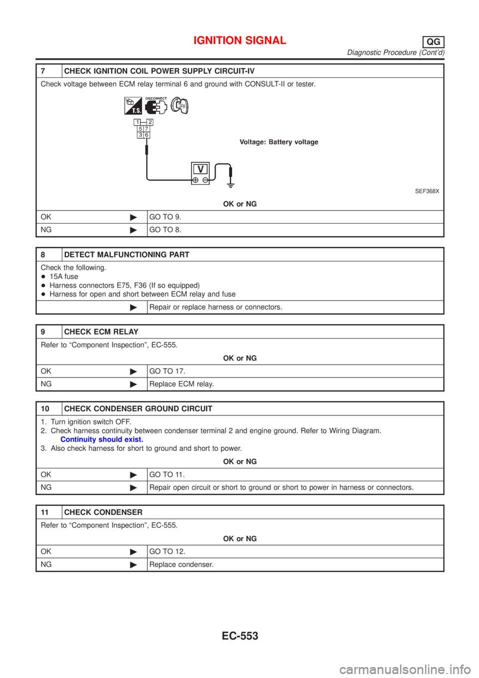
7 CHECK IGNITION COIL POWER SUPPLY CIRCUIT-IV
Check voltage between ECM relay terminal 6 and ground with CONSULT-II or tester.
SEF368X
OK or NG
OK©GO TO 9.
NG©GO TO 8.
8 DETECT MALFUNCTIONING PART
Check the following.
+15A fuse
+Harness connectors E75, F36 (If so equipped)
+Harness for open and short between ECM relay and fuse
©Repair or replace harness or connectors.
9 CHECK ECM RELAY
Refer to ªComponent Inspectionº, EC-555.
OK or NG
OK©GO TO 17.
NG©Replace ECM relay.
10 CHECK CONDENSER GROUND CIRCUIT
1. Turn ignition switch OFF.
2. Check harness continuity between condenser terminal 2 and engine ground. Refer to Wiring Diagram.
Continuity should exist.
3. Also check harness for short to ground and short to power.
OK or NG
OK©GO TO 11.
NG©Repair open circuit or short to ground or short to power in harness or connectors.
11 CHECK CONDENSER
Refer to ªComponent Inspectionº, EC-555.
OK or NG
OK©GO TO 12.
NG©Replace condenser.
IGNITION SIGNALQG
Diagnostic Procedure (Cont'd)
EC-553
Page 1278 of 2898
12 CHECK IGNITION COIL POWER SUPPLY CIRCUIT-V
1. Turn ignition switch OFF.
2. Reconnect harness connectors disconnected.
3. Disconnect ignition coil harness connector.
JEF119Y
4. Turn ignition switch ON.
5. Check voltage between ignition coil terminal 1 and ground with CONSULT-II or tester.
SEF122Y
OK or NG
OK©GO TO 14.
NG©GO TO 13.
13 DETECT MALFUNCTIONING PART
Check the following.
+Harness connector E75, F36 (If so equipped)
+Harness for open or short between ignition coil and ECM relay terminal 7
©Repair or replace harness or connectors.
14 CHECK IGNITION COIL GROUND CIRCUIT
1. Turn ignition switch OFF.
2. Check harness continuity between ignition coil terminal 2 and engine ground. Refer to Wiring Diagram.
Continuity should exist.
3. Also check harness for short to ground and short to power.
OK or NG
OK©GO TO 15.
NG©Repair open circuit or short to ground or short to power in harness or connectors.
IGNITION SIGNALQG
Diagnostic Procedure (Cont'd)
EC-554
Page 1279 of 2898

15 CHECK IGNITION COIL OUTPUT SIGNAL CIRCUIT
1. Disconnect ECM harness connector.
2. Check harness continuity between ECM terminals 35, 36, 37, 38 and ignition coil terminal 3. Refer to Wiring Diagram.
Continuity should exist.
3. Also check harness for short to ground and short to power.
OK or NG
OK©GO TO 16.
NG©Repair open circuit or short to ground or short to power in harness or connectors.
16 CHECK IGNITION COIL WITH POWER TRANSISTOR
Refer to ªComponent Inspectionº, EC-555.
OK or NG
OK©GO TO 17.
NG©Replace ignition coil with power transistor.
17 CHECK INTERMITTENT INCIDENT
Refer to ªTROUBLE DIAGNOSIS FOR INTERMITTENT INCIDENTº, EC-177.
©INSPECTION END
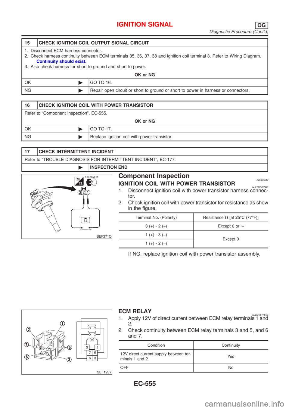
SEF371Q
Component InspectionNJEC0547IGNITION COIL WITH POWER TRANSISTORNJEC0547S011. Disconnect ignition coil with power transistor harness connec-
tor.
2. Check ignition coil with power transistor for resistance as show
in the figure.
Terminal No. (Polarity) ResistanceW[at 25ÉC (77ÉF)]
3 (+) - 2 (þ) Except 0 or¥
1 (+) - 3 (þ)
Except 0
1 (+) - 2 (þ)
If NG, replace ignition coil with power transistor assembly.
SEF123Y
ECM RELAYNJEC0547S031. Apply 12V of direct current between ECM relay terminals 1 and
2.
2. Check continuity between ECM relay terminals 3 and 5, and 6
and 7.
Condition Continuity
12V direct current supply between ter-
minals 1 and 2Ye s
OFF No
IGNITION SIGNALQG
Diagnostic Procedure (Cont'd)
EC-555
Page 1282 of 2898
Wiring DiagramNJEC0440
HEC812
START SIGNALQG
Wiring Diagram
EC-558
Page 1287 of 2898
Wiring DiagramNJEC0447
HEC813
FUEL PUMPQG
Wiring Diagram
EC-563
Page 1289 of 2898

3 DETECT MALFUNCTIONING PART
Check the following.
+10A fuse
+15A fuse
+Harness for open or short between fuse and fuel pump relay
©Repair harness or connectors.
4 CHECK POWER GROUND CIRCUIT
1. Turn ignition switch ªOFFº.
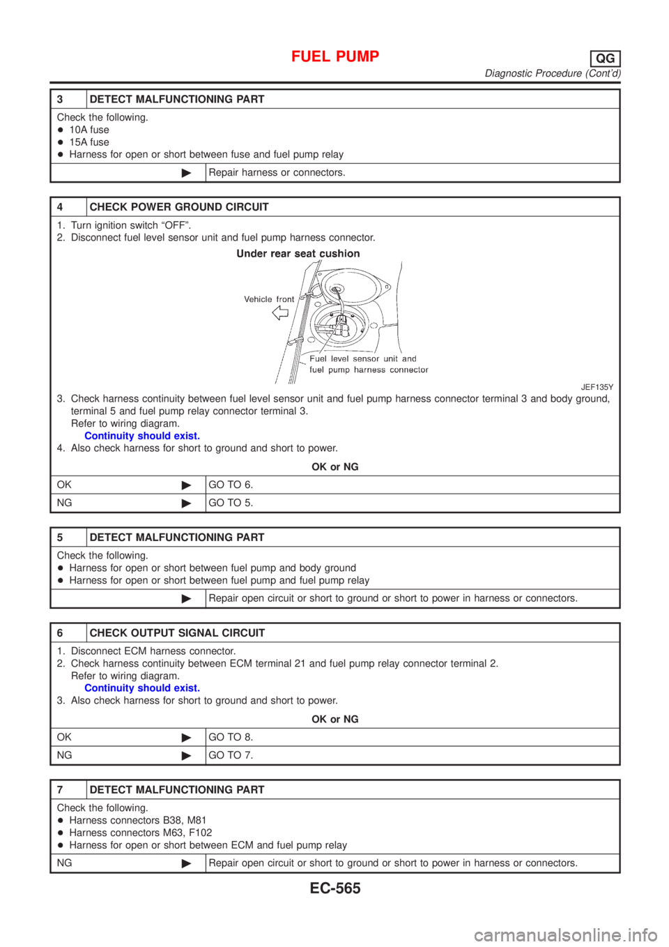
2. Disconnect fuel level sensor unit and fuel pump harness connector.
JEF135Y
3. Check harness continuity between fuel level sensor unit and fuel pump harness connector terminal 3 and body ground,
terminal 5 and fuel pump relay connector terminal 3.
Refer to wiring diagram.
Continuity should exist.
4. Also check harness for short to ground and short to power.
OK or NG
OK©GO TO 6.
NG©GO TO 5.
5 DETECT MALFUNCTIONING PART
Check the following.
+Harness for open or short between fuel pump and body ground
+Harness for open or short between fuel pump and fuel pump relay
©Repair open circuit or short to ground or short to power in harness or connectors.
6 CHECK OUTPUT SIGNAL CIRCUIT
1. Disconnect ECM harness connector.
2. Check harness continuity between ECM terminal 21 and fuel pump relay connector terminal 2.
Refer to wiring diagram.
Continuity should exist.
3. Also check harness for short to ground and short to power.
OK or NG
OK©GO TO 8.
NG©GO TO 7.
7 DETECT MALFUNCTIONING PART
Check the following.
+Harness connectors B38, M81
+Harness connectors M63, F102
+Harness for open or short between ECM and fuel pump relay
NG©Repair open circuit or short to ground or short to power in harness or connectors.
FUEL PUMPQG
Diagnostic Procedure (Cont'd)
EC-565
Page 1292 of 2898
Wiring DiagramNJEC0450
HEC814
POWER STEERING OIL PRESSURE SWITCHQG
Wiring Diagram
EC-568