Page 1261 of 2898
Wiring DiagramNJEC1782
HEC913
PARK/NEUTRAL POSITION (PNP) SWITCHQG
Wiring Diagram
EC-537
Page 1263 of 2898

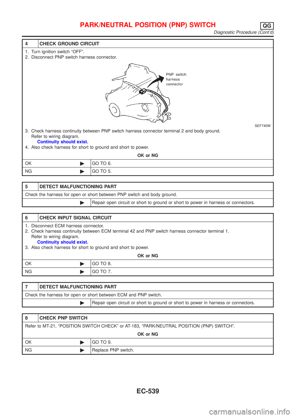
4 CHECK GROUND CIRCUIT
1. Turn ignition switch ªOFFº.
2. Disconnect PNP switch harness connector.
SEF740W
3. Check harness continuity between PNP switch harness connector terminal 2 and body ground.
Refer to wiring diagram.
Continuity should exist.
4. Also check harness for short to ground and short to power.
OK or NG
OK©GO TO 6.
NG©GO TO 5.
5 DETECT MALFUNCTIONING PART
Check the harness for open or short between PNP switch and body ground.
©Repair open circuit or short to ground or short to power in harness or connectors.
6 CHECK INPUT SIGNAL CIRCUIT
1. Disconnect ECM harness connector.
2. Check harness continuity between ECM terminal 42 and PNP switch harness connector terminal 1.
Refer to wiring diagram.
Continuity should exist.
3. Also check harness for short to ground and short to power.
OK or NG
OK©GO TO 8.
NG©GO TO 7.
7 DETECT MALFUNCTIONING PART
Check the harness for open or short between ECM and PNP switch.
©Repair open circuit or short to ground or short to power in harness or connectors.
8 CHECK PNP SWITCH
Refer to MT-21, ªPOSITION SWITCH CHECKº or AT-183, ªPARK/NEUTRAL POSITION (PNP) SWITCHº.
OK or NG
OK©GO TO 9.
NG©Replace PNP switch.
PARK/NEUTRAL POSITION (PNP) SWITCHQG
Diagnostic Procedure (Cont'd)
EC-539
Page 1266 of 2898
Wiring DiagramNJEC0434SEDAN MODELS AND HATCHBACK MODELS WITH
ECM IN ENGINE COMPARTMENT
NJEC0434S01
HEC809
INJECTORQG
Wiring Diagram
EC-542
Page 1267 of 2898
HATCHBACK MODELS WITH ECM IN CABINNJEC0434S02
HEC963
INJECTORQG
Wiring Diagram (Cont'd)
EC-543
Page 1269 of 2898

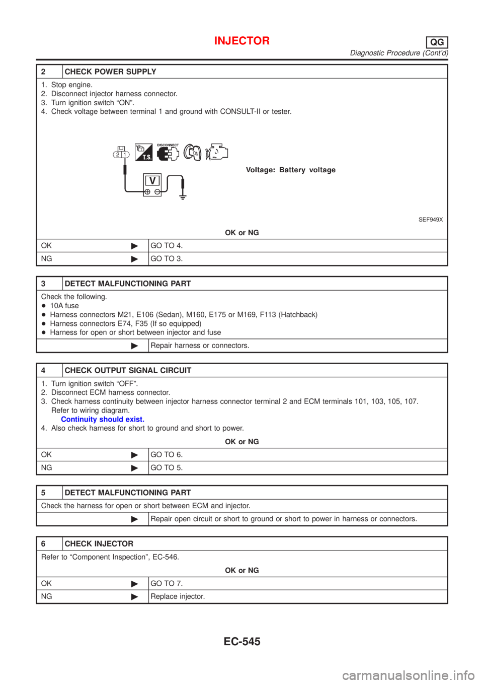
2 CHECK POWER SUPPLY
1. Stop engine.
2. Disconnect injector harness connector.
3. Turn ignition switch ªONº.
4. Check voltage between terminal 1 and ground with CONSULT-II or tester.
SEF949X
OK or NG
OK©GO TO 4.
NG©GO TO 3.
3 DETECT MALFUNCTIONING PART
Check the following.
+10A fuse
+Harness connectors M21, E106 (Sedan), M160, E175 or M169, F113 (Hatchback)
+Harness connectors E74, F35 (If so equipped)
+Harness for open or short between injector and fuse
©Repair harness or connectors.
4 CHECK OUTPUT SIGNAL CIRCUIT
1. Turn ignition switch ªOFFº.
2. Disconnect ECM harness connector.
3. Check harness continuity between injector harness connector terminal 2 and ECM terminals 101, 103, 105, 107.
Refer to wiring diagram.
Continuity should exist.
4. Also check harness for short to ground and short to power.
OK or NG
OK©GO TO 6.
NG©GO TO 5.
5 DETECT MALFUNCTIONING PART
Check the harness for open or short between ECM and injector.
©Repair open circuit or short to ground or short to power in harness or connectors.
6 CHECK INJECTOR
Refer to ªComponent Inspectionº, EC-546.
OK or NG
OK©GO TO 7.
NG©Replace injector.
INJECTORQG
Diagnostic Procedure (Cont'd)
EC-545
Page 1272 of 2898
Wiring DiagramNJEC1784SEDAN MODELS AND HATCHBACK MODELS WITH ECM IN ENGINE COMPARTMENTNJEC1784S01
HEC964
IGNITION SIGNALQG
Wiring Diagram
EC-548
Page 1273 of 2898
HATCHBACK MODELS WITH ECM IN CABINNJEC1784S02
HEC979
IGNITION SIGNALQG
Wiring Diagram (Cont'd)
EC-549
Page 1274 of 2898
HEC965
IGNITION SIGNALQG
Wiring Diagram (Cont'd)
EC-550